Table of Contents
Advertisement
Quick Links
Advertisement
Table of Contents

Related Manuals for MTS Systems Level Plus LP Series


Summary of Contents for MTS Systems Level Plus LP Series
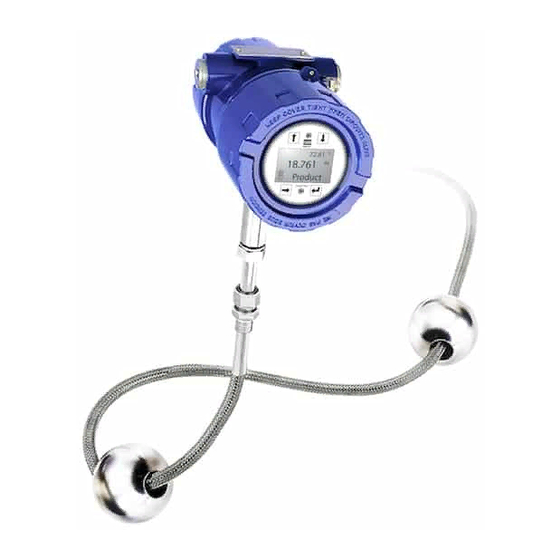
- Page 1 Level Plus ® Magnetostrictive Liquid Level Transmitters with Temposonics Technology ® Safety Manual LP Series S a f e t y I n t e g r i t y L e v e l IEC 61508 S a f e t y I n t e g r i t y L e v e l IEC 61508 S a f e t y I n t e g r i t y L e v e l...
-
Page 2: Table Of Contents
LP Safety Manual LP Series Table of contents 1. Contact information ......................................3 2. Introduction ........................................3 3. Function ........................................... 4 3.1 Safety Rated Function ....................................4 3.2 Non-Safety Rated Function ..................................4 4. SIL Information ........................................ 4 4.1 SIL Rating ........................................4 4.2 Intended use ...................................... -
Page 3: Contact Information
1. Contact information United States General Tel: +1-919-677-0100 Fax: +1-919-677-2343 E-mail: info.us@mtssensors.com http://www.mtssensors.com Mailing and shipping address MTS Systems Corporation Sensors Division 3001 Sheldon Drive Cary, North Carolina, 27513, USA Customer service Tel: +1-800-633-7609 Fax: +1-800-498-4442 E-mail: info.us@mtssensors.com Technical support and applications... -
Page 4: Introduction
LP Safety Manual LP Series 2. Introduction 4.2 Intended Use The LP Series SIL capable level transmitters is a magnetostrictive liquid level transmitter certified according to IEC 61508 for single input in low This manual provides to the user electrical installation and operation demand, SIL 2 Safety Instrumented Systems. -
Page 5: Quick Start-Up Guide
LP Safety Manual LP Series Tools needed: 5. Specifications • 24 Vdc linear regulated power supply • Current meter Level Output Inherent Accuracy ±1 mm (0.039 in.) Safety Accuracy Limit ±2% Full Scale 6.2 Quick start-up procedure Connect 24 Vdc power supply to Loop 1. Order length Flexible hose: Turn on power supply. -
Page 6: Run Mode
LP Safety Manual LP Series 7.2 Display Diagram 7.1.2 Run Mode After initialization is completed, the level transmitter begins continuous measurement operations in run mode. For SIL, diagnostics are continu- ally run to detect possible hardware and software failures and to set the output into the safe state if a fault condition is determined. -
Page 7: Alarms
LP Safety Manual LP Series • Calibrate Internal Cycle power to sensor. If proper opera- ƒ Product Level Fault 4 tion is not restored, Contact Factory ` Current Level Peak Fault • Verify Auto Threshold is enabled ` Offset • Cycle power to sensor ƒ... -
Page 8: Hart ® Interface
LP Safety Manual LP Series 10. HART Interface ® MTS has tested and is compliant to HART ® ITK 7.2. The device driver file is available for download from HART ® Communication Protocol website at www.fieldcommgroup.org. Programming via HART ® can be done either using the LP Dashboard via a HART ®... -
Page 9: Configuration
LP Safety Manual LP Series Display Setting: Allows the end user to configure the display. Availab- The analog panel is on the bottom. On the left side is the graphical and numerical value for percent full ranging from 0 to 100 percent. Loop 1 is le options are engineering units, current output, or percent full. -
Page 10: Temperature Settings
LP Safety Manual LP Series Factory Set: 10.1.5 Temperature settings PV: is the Primary Variable in HART® and the default setting is the Product Level. For SIL units, the PV cannot be changed from the Product level. SV: is the Secondary Variable in HART® and the default setting is the Interface Level. -
Page 11: Flash Settings
LP Safety Manual LP Series 10.1.7 Flash settings Write Setting to a File: Allows the end user to download a backup file of factory parameters from the LP Dashboard to a PC. This task is usually performed after Read Settings from Gauge. Note – wait until all settings have changed from Red to White before writing as the color change signals that the settings have been updated. -
Page 12: Handheld Programming
LP Safety Manual LP Series 10.2 Handheld Programming Offsets Float 1 Offset 10.2.1 Handheld Menu Tree Float 2 Offset LCD settings NOTICE Screen delay The LP-Series driver must be loaded on the handheld HART ® ... - Page 13 LP Safety Manual LP Series 10.2.2 Handheld Menu Screenshots 10.2.2.1 Online Menu Screen Fig. 14: Write Protect Disabled Parameters Write Protect - user can turn disable or enable write protect mode. Fig. 12: Online Screen While write protect is enable no variables can be changed and the full Parameters menu tree cannot be seen.
- Page 14 LP Safety Manual LP Series 10.2.2.4 PV Menu Tree 10.2.2.6 TV Menu Screen Fig. 16: PV Menu Tree Fig. 17: TV Menu Tree Parameters Level 1 LRV – lower range value of the PV that correlates to the Parameters location of the 4 mA set point of the output. Temp LRV –...
- Page 15 LP Safety Manual LP Series 10.2.2.10 Loop Test Menu Tree Fig. 20: Test Device Menu Screen Fig. 21: Loop Test Menu Tree 10.2.2.8 Test device Menu Screen Parameters Parameters Self Test – allows user to force level transmitter to check for fault 4 mA –...
- Page 16 LP Safety Manual LP Series 10.2.2.12 Detailed setup Menu Screen 10.2.2.14 Configuration Menu Screen Fig. 25: Configuration Menu Screen Fig. 24: Detailed Setup Menu Screen Parameters Parameters Variable mapping – allows the user to select the MTS variables that Sys Config – allows access to MTS factory parameters are mapped to the PV, SV, and TV Gradient –...
- Page 17 LP Safety Manual LP Series 10.2.2.16 Offsets Menu Screen 10.2.2.18 Sensors Menu Screen Fig. 28: Offsets Menu Screen Fig. 29: Sensors Menu Screen Parameters Parameters Float 1 Offset – allows user to change the offset of the product level Level 1 – allows user to access parameters and data for product level. that is used for calibration.
- Page 18 LP Safety Manual LP Series 10.2.2.19 Level 1 Menu Screen Level 2 Damp – damping parameter for interface level Data Level 2 – actual product level in units of measure Level 2 Class – variable class for interface level Level 2 Min span – the minimum distance required between the Level 2 LRV and Level 2 URV Fig.
-
Page 19: Display Programming
LP Safety Manual LP Series 10.3.1.1 Data From Device 10.2.2.22 HART output Menu Screen ® Fig. 36: Display “Data from Device” Display – Allows the user to change the displayed value between engineering units, milliamps, and percentage. Fig. 34: HART output Menu Screen ®... - Page 20 LP Safety Manual LP Series 10.3.1.1.2 Units 10.3.1.1.3 Set Points Fig. 41: Display “Set Points” Fig. 38: Display “Units” Length Units – Allows the user to select the units of measure for the Prod LVR (4 mA) – Allows the user to change the Loop 1 4 mA set level measurement point by changing the numerical value Temp Units –...
- Page 21 LP Safety Manual LP Series 10.3.1.1.3.2 Prod URV (20 mA) 10.3.1.1.3.5 Int LRV (4 mA) Fig. 43: Display “Prod URV (20 mA)” Fig. 46: Display “PInt LRV (4 mA)” Set the Loop 1 20 mA set point by changing the numerical value Set the Loop 2 4 mA set point by changing the numerical value 10.3.1.1.3.3 Prd Current LRV 10.3.1.1.3.6 Int URV (20 mA)
- Page 22 LP Safety Manual LP Series 10.3.1.1.3.8 Int Current URV 10.3.1.1.5.1 Prod Trig Lvl Fig. 52: Display “Prod Trig Lvl” Fig. 49: Display “Int Current URV” Set the Loop 2 20 mA set point by moving the float to the desired Numerical value for the strength of the return signal, cannot be edited.
- Page 23 LP Safety Manual LP Series 10.3.1.2.1 Product Level 10.3.1.2.2 Interface Level Fig. 55: Display “Product Level” Fig. 58: Display “Interface Level” Current Level – allows the user to calibrate based on the current tank Current Level – allows the user to calibrate based on the current tank level level Offset –...
- Page 24 LP Safety Manual LP Series 10.3.1.3 Factory 10.3.1.3.1.1 Serial Number Fig. 63: “Serial Number” Fig. 61: “Factory” Settings – Allows the user to access factory settings Serial Number assigned by MTS at the time of manufacture. The serial Temp Setup- Allows the user to setup temperature measurement if number is used for tracking and replacement parts equipped Float Config –...
- Page 25 LP Safety Manual LP Series 10.3.1.3.2 Temp Setup 10.3.1.3.3 Float Config Fig. 69: “Float Config” Fig. 66: “Temp Setup” Loop 2 – Allows the user to turn on or off the interface level float. Temp Enable – Allows the user to turn the temperature measurement Does not change the number of floats on the level transmitter.
-
Page 26: Data From Device
LP Safety Manual LP Series 10.4. Data from Device SARA Blanking Initial blanking distance from the head of the level transmitter. Do not Display change. Allows the user to select if the display shows engineering units, mA, or percent full. Magnet Blanking Blanking distance between two floats. -
Page 27: Proof Test
LP Safety Manual LP Series 11. Proof Test 12. Change Request The Safety Function of the LP-Series SIL capable level transmitter is If there are any issues during system integration then contact MTS and internally checked but the diagnostic coverage of the sensor can be issue a change rquest. - Page 28 MTS, Temposonics and Level Plus are registered trademarks of MTS Systems Corporation in the United States; MTS SENSORS and the MTS SENSORS logo are trademarks of MTS Systems Corporation within the United States. These trademarks may be protected in other countries. All other trademarks are the property of their respective owners. Copyright © 2021 MTS Systems Corporation. No license of any intellectual property rights is granted.
Need help?
Do you have a question about the Level Plus LP Series and is the answer not in the manual?
Questions and answers