Mutec MC-3+ Smart Clock USB Operating Manual
Hide thumbs
Also See for MC-3+ Smart Clock USB:
- Quick start manual (4 pages) ,
- Quick start manual (4 pages) ,
- Operating manual (22 pages)
Table of Contents

Related Manuals for Mutec MC-3+ Smart Clock USB


Summary of Contents for Mutec MC-3+ Smart Clock USB
- Page 1 Operating Manual MU TE C Gmb H · F on 0049- (0) 30- 74 68 8 0-0 · cont act @m utec- net. com · www. mutec-net. com f a cebo o k. co m/ mu t ec pr o pinte re st.com/mutecp ro...
-
Page 3: Table Of Contents
Control Elements and Terminals Front Panel ....................................12 Rear Panel ....................................13 USB Driver Installation & Windows Settings MUTEC USB Audio Class 2.0 Driver for Windows ........................15 Driver Download and Installation Procedure ..........................16 Windows Settings ..................................17 Operation General System Operation ................................ -
Page 4: Safety Instructions
We herewith confirm that the product complies with the mediately! If the unit is damaged, please do NOT return it to MUTEC GmbH, but notify your European Commission’s standards on electromagnetic dealer and the shipping company immediately, otherwise claims for damage or replacement compatibility. -
Page 5: Warranty Regulations
§1 Warranty MUTEC GmbH warrants the flawless performance of this product to the original buyer for a period of two (2) years from the date of purchase. If any failure occurs within the specified warranty period that is caused by defects in material and/or workmanship, MUTEC GmbH shall either repair or replace the product free of charge within 90 days. -
Page 6: Quick Start Guide
Windows Driver Installation In order to operate the MC-3+USB with a Windows computer it is required to install MUTEC’s USB Audio Class 2.0 Driver for Windows available on our website. The driver provides an ASIO-2.2 compliant software interface and interacts with Windows as a standard WDM/DirectX compatible sound device. -
Page 7: Hardware Setup
MAC Software Setup The MC-3+ Smart Clock USB acts as a class-compliant Core Audio device on MAC computers. Therefore, there is no need for any driver installation. When the MC-3+USB is powered up and a USB connection has been established, your MAC will automatically detect the new audio device and select it as the current playback device. -
Page 8: General Description & Features
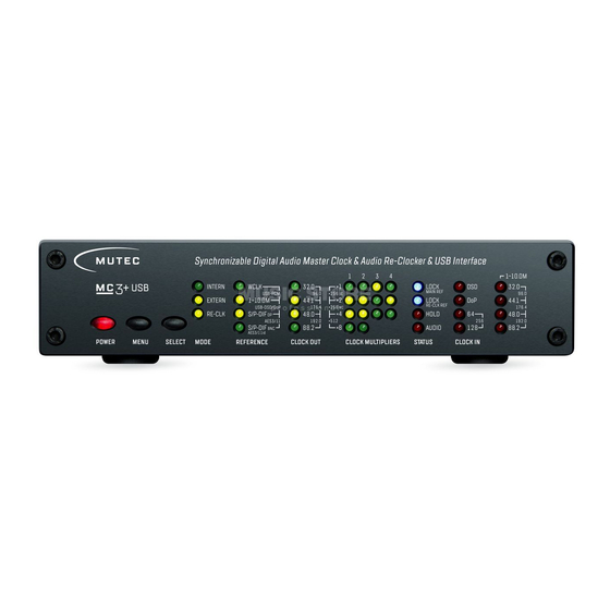
Introduction General Description The MC-3+ Smart Clock USB is setting a new benchmark for clocking technology and the reproduction of digital audio by uniquely combining an audiophile USB interface with an audio re-clocker in perfection! The MC-3+USB’s improvements to the sound quality of connected devices are two-fold: first as an ultra-low jitter clock with industry-leading precision and noise performance, and secondly by aggressively re-clocking incoming digital audio signals. -
Page 9: Product Registration For Warranty And Support & Social Media
MW-03/19, Set of two rack mounting angles to install one MC product on the rear side of a 19” rack. MW-05/19, Set of two rack mounting angles to install one MC product frontally into one unit of a 19” rack. For all peripheral products please have a look on our website: www.mutec-net.com... -
Page 10: Installation
Product Registration for Warranty and Support We ask you to be so kind to register your MUTEC product through our website immediately after buying. This ensures full warranty services over a period of two years after purchasing the product. More-over, for all registered products we offer to our customers technical support. -
Page 11: Wiring The Interfaces & General Recommendations For Interface Wirings & Cables
Installation Wiring the Interfaces Word Clock To allow for the synchronization of signals, the interfaces of all devices involved must be properly connected to each other to ensure a logical signal flow. Always be sure to connect the Word Clock output(s) to the corresponding input(s) of the device(s) you wish to synchronize. -
Page 12: Control Elements And Terminals
Control Elements and Terminals Information MUTEC offers optical cables of various lengths that have been specifically tested for the transmission of ADAT™ and S/P-DIF signals. Ask your local dealer for such cables! Control Elements and Terminals Front Panel 1 »POWER«... -
Page 13: Rear Panel
Control Elements and Terminals Rear Panel 1 »WCLK OUT 1 – 2« These 2 pairs of Word Clock outputs transfer all standard Word Clock rates, Word Clock × 256 for older digidesign ProTools™ systems and × 512 clock rates for special High-End interfaces. Their numbering is aligned to the apropriate menus on the front panel. - Page 14 Control Elements and Terminals 9 »S/P-DIF & AESid IN« This input receives either an unbalanced electrical digital audio or blank-frame signal in compliance with AES3id-2001 (revision of 1995) or AES11-2003 (revision of 1997), or an unbalanced electrical digital audio or blank-frame signal in compliance with the IEC 60958 standard.
-
Page 15: Usb Driver Installation & Windows Settings
Windows XP at 32 bit (x86) only The MUTEC USB Audio Class 2.0 Driver for Windows is designed for professional use as well as audiophile High-End applica- tions and thus compatible to most of the well-known software music players. It supports devices which are compliant to the USB Audio Class 1.0 or USB Audio Class 2.0 device specifications. -
Page 16: Driver Download And Installation Procedure
USB Driver Installation & Windows Settings Driver Download and Installation Procedure Please go to our website to download the MUTEC USB Audio Class 2.0 Driver for Windows as follows: www.mutec-net.com > Products > USB Interfaces > MC-3+USB > Downloads Or for direct access type in the following URL into your browser: http://http://www.mutec-net.com/product_mc-3-plus-usb.php?lng=en... -
Page 17: Windows Settings
Windows Settings After installation of the MUTEC USB Audio Class 2.0 Driver for Windows is successfully completed, you can connect your MC-3+USB to one of your computer’s USB ports by using the USB cable included in the scope of delivery. Switch on your MC-3+USB and it should be automatically recognoized by your computer‘s operating system. - Page 18 USB Driver Installation & Windows Settings In the »Playback« tab select »MC-3+ Smart Clock USB« Click now on »Properties«. from the list of available devices and click at »Set Default«. after that the green check mark changes to the MC-3+USB entry.
-
Page 19: Operation
Operation General System Operation Operating the MC-3+USB is very easy! The device is fully operated using the two keys on the front panel. »MENU« Key Pressing the »MENU« key toggles between different basic function menus, usually between the vertical LED columns. »SELECT«... -
Page 20: Operation Of The Mc-3+ Smart Clock Usb
Operation Operation of the MC-3+ Smart Clock USB Main Function Menus The four main function menus provide access to all features of your MC-3+USB. Select the operational mode of the MC-3+USB via the »MODE« menu. This needs to be selected first. The factory default is »INTERN«. - Page 21 Operation »EXTERN« – Selecting external Clock References External clock references can be selected when the MC-3+USB is set to »EXTERN« in the »MODE« menu. 1 – 10.0M LOCK × 1 INTERN WCLK 32.0 32.0 MAIN REF 96.0 × 256 USB - PCM 96.0 LOCK ×...
- Page 22 »EXTERN« & »RE-CLK« This is a very unique feature that is only available in your MC-3+ Smart Clock USB! After selecting the first re-clocking mode, press the »SELECT« key once again and the »EXTERN« and »RE-CLK« will light up to indicate that re-clocking based on an externally applied clock reference is now active.
- Page 23 Operation Different DoP Standards There are two different DoP code conventions. DSD data in a PCM stream will be identified with so called “markers”. The first (official) convention utilizes two alternating markers with the values 0x05 and 0xFA, also called DoP markers. The second convention uses a fixed marker with the value 0xAA, also called dCS marker.
-
Page 24: Status Information & Generic Functions
Operation Status Information The »STATUS« and »CLOCK « sections are strictly for monitoring the operational status of the MC-3+USB. They are not acces- sible for user adjustments via the keys. STATUS »LOCK MAIN REF« & »LOCK RE-CLK REF« The blue LED »LOCK MAIN REF« illuminates when the internal PLL circuit has detected a valid clock reference in the inco- ming clock, audio or USB stream signals. - Page 25 Operation Front Panel lock out + LED shut down When pressing both front panel keys together at one time, all LEDs will shut down except the »POWER« and »LOCK« LEDs. Additionally, the functions of both keys are also blocked to prevent unauthorized operation, which is important during e.g. live events.
-
Page 26: Appendix
Appendix Pin Assignment of the Connectors Mains BNC Input/Output for Optical TOSLINK Input/Output Word Clock, 10.0 MHz for S/P-DIF 1 Optical signal 1 Live, phase (brown; USA: black) 1 Signal 2 Protective earth (green/yellow; USA: green) 2 Ground 3 Neutral (blue; USA: white) AES/EBU, XLR, Input AES/EBU, XLR, Output RCA, Input/Output... - Page 27 Appendix If you want to switch-off the termination, remove carefully the jumper from the two pins of position 2 of the socket and plug it onto the two pins of position 1 (see adjacent sletch). Attention The jumper must be plugged on position one of the socket – do not omit him! Jumper Position 1 = no Termination Inside View –...
-
Page 28: Technical Data
XX XX Appendix Technical Data USB In- & Output (USB I/O) Interface 1 x USB-B connector Formats & Resolutions Type 1 Formats: PCM 16 bit, PCM 24 bit, PCM 32 bit, FLOAT 32 bit für USB 1.0 & USB 2.0 Supported PCM Sampl. -
Page 29: Generatable Word Clock (Wclk) Frequencies & Generatable Aes11 & S/P-Dif Blank Frame Frequencies
2500 V RMS aligned to UL1577, 4242 V PK aligned to DIN EN 60747-5-2 (VDE 0882, part 2) Frequenzsynthese & Referenztakt Spezifikationen Frequency Synthesis MUTEC’s propritary 1G-Clock Technology based on highest-clocked DDS process Oscillator Type XO, digitally-compensated crystal oscillator Clock Accuracy (shipped) <... - Page 30 MU TE C Gmb H · F on 0049- (0) 30- 74 68 8 0-0 · cont act @m utec- net. com · www. mutec-net. com f a cebo o k. co m/ mu t ec pr o pinte re st.com/mutecp ro...
Need help?
Do you have a question about the MC-3+ Smart Clock USB and is the answer not in the manual?
Questions and answers