Table of Contents
Advertisement
Quick Links
Advertisement
Table of Contents

Related Manuals for Megger DLRO10HD


Summary of Contents for Megger DLRO10HD
- Page 1 DLRO10HD and DLRO10HDX 10 A Digital Low Resistance Ohmmeter User Guide...
-
Page 3: Table Of Contents
Automatic Bi-directional Test (Manual Save) ....................17 Automatic Uni-directional Test (Automatic Save) ...................18 Automatic Uni-directional Test (Manual Save) ....................19 Continuous Test (Automatic Save) .........................20 Continuous Test (Manual Save During Test) ....................21 Continuous Test (Manual Save After Test) ......................22 Inductive Test ..............................23 www.BiddleMegger.com DLRO10HD / DLRO10HDX... - Page 4 Test Leads with an In-line Connector ......................31 Repair and Warranty Calibration, Service and Spare Parts ......................32 Approved Repair Companies .........................32 Return an Instrument for Repair ........................32 End of Life Disposal WEEE Directive ..............................33 Batteries ..............................33 Deceleration of Conformity www.BiddleMegger.com .com DLRO10HD / DLRO10HDX...
-
Page 5: Instrument Safety
„ There are no user-serviceable parts inside the instrument; all servicing, including battery and fuse replacement, must be referred a Megger approved service centre „ When used on hazardous voltages the Megger terminal cover (part number 1002-390) must be used www.BiddleMegger.com... -
Page 6: Measurement Connection
„ This product is not intrinsically safe. Do not use in an explosive atmosphere Measurement Connection Only Megger supplied test leads designed for this instrument provide the full safety rating. Voltage The rated measurement connection voltage is the maximum line to earth voltage at which it is safe to connect. -
Page 7: Warning Icons
1 mA is still flowing after an inductive test is completed. This suggests that the inductive load has been tested and is discharging. Do not disconnect the current loop while the discharge warning is showing. www.BiddleMegger.com DLRO10HD / DLRO10HDX... -
Page 8: Description
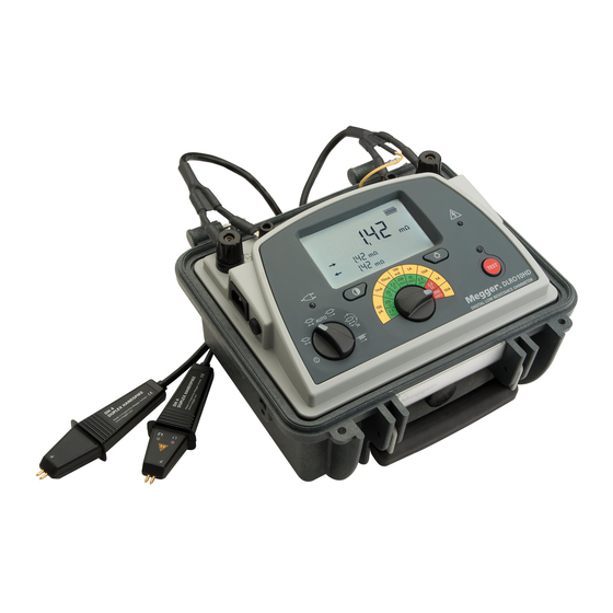
Description This User Guide details the DLRO10HD and the DLRO10HDX. Both the DLRO10HD and the DLRO10HDX measure the same tests and parameters, in addition the DLRO10HDX can save, recall and download test results to PowerDB. The DLRO10 range of digital low resistance ohm meters measure resistance in a range of 0.1 µΩ to 2 k. These instruments provide a maximum test current of 10 Amps. -
Page 9: Applications
The DLRO10HD is well suited to measuring thick conductors, bonds and quality of welding because of its 10 A range for resistance values up to 250 mΩ. Measurements on electric motors and generators will be inductive and require the User to understand the inductive mode and charging process before a correct result is achieved. -
Page 10: Overview
Test Lead LED Cable Test modes and Off rotary switch Display Mains Power On LED Save Button Fuse USB socket (download records) Contrast button Hazard warning LED during test Mains Power Socket Range Rotary Switch Back-light www.BiddleMegger.com .com DLRO10HD / DLRO10HDX... -
Page 11: Display Icons
USB connected Primary Display Mains Power connected Direction of Current flow in a test Battery Status Secondary Display Directional arrow to show current flow above C indicator Directional arrow to show current flow above P indicator www.BiddleMegger.com DLRO10HD / DLRO10HDX... -
Page 12: Test Mode Rotary Switch
Note: When inductive loads are measured it is necessary to wait for the voltage to stabilise, so the measurement process can take a few seconds or several minutes. www.BiddleMegger.com .com DLRO10HD / DLRO10HDX... -
Page 13: Range Rotary Switch
Delete a single or all test result records (DLRO10HDX only (see”Memory Features” on page 24)) Download Records Download test result records to PowerDB (DLRO10HDX only (see”Memory Features” on page 24)) Recall Records Recall and view previous test result records (DLRO10HDX only (see”Memory Features” on page 24)) www.BiddleMegger.com DLRO10HD / DLRO10HDX... -
Page 14: Resolution And Accuracy
25 W * Basic accuracy stated assumes forward and reverse measurements. ** Warning icon shows Inductive or Uni-directional mode can introduce an undefined error if an external EMF is present. Basic accuracy at reference conditions. www.BiddleMegger.com .com DLRO10HD / DLRO10HDX... -
Page 15: Test Leads
The earth terminal is used to detect floating voltage on the test subject relative to the Instrument’s 0 V. High floating voltage on the test subject could be a hazard to the User and the Instrument. If the test subject is ±200 mV from the Instrument 0 V, the test will be inhibited. www.BiddleMegger.com DLRO10HD / DLRO10HDX... -
Page 16: Dh4-C Duplex Hand-Spikes
Tests with the DH4-C Duplex Hand-spikes or Individual Leads Connect the four leads as shown. In all cases make sure that the potential probes (P1 and P2) are inside the current (C1 and C2) probes. www.BiddleMegger.com .com DLRO10HD / DLRO10HDX... -
Page 17: Date And Time Setup
D:M:Y or M:D:Y format (Default: DMY). Press to toggle between Date and Time 1. Press to start adjustment. 2. Press to toggle between D/M/Y and HM 3. Press to adjust 4. Press to scroll 5. Press to set www.BiddleMegger.com DLRO10HD / DLRO10HDX... -
Page 18: Tests
The result in Bi-directional modes is the average of two readings shown by the two secondary displays, with arrows to show the direction of current flow. The large arrow at the top of the display between C1 and C2 shows the measurement current flow. www.BiddleMegger.com .com DLRO10HD / DLRO10HDX... -
Page 19: Manual Bi-Directional Test
The Save screen is shown for three seconds. TEST 3. If the test piece is still connected, press to do another test. TEST 4. Remove the clamps and press to stop the test. www.BiddleMegger.com DLRO10HD / DLRO10HDX... -
Page 20: Automatic Bi-Directional Test (Automatic Save)
Test results are saved and their memory slot number is shown. The Save screen is shown for three seconds. 4. The test automatically continues for the next connected test piece. TEST 5. Press to stop the test. www.BiddleMegger.com .com DLRO10HD / DLRO10HDX... -
Page 21: Automatic Bi-Directional Test (Manual Save)
. The test result is saved and its memory slot number is shown. The Save screen is shown for three seconds. 4. The test automatically continues for subsequent connected test piece. 5. Press as required. TEST 6. Press to stop the test. www.BiddleMegger.com DLRO10HD / DLRO10HDX... -
Page 22: Automatic Uni-Directional Test (Automatic Save)
4. Test results are saved and their memory slot number is shown. The Save screen is shown for three seconds. 5. The test automatically continues for the next connected test piece. TEST 6. Press to stop the test. www.BiddleMegger.com .com DLRO10HD / DLRO10HDX... -
Page 23: Automatic Uni-Directional Test (Manual Save)
. The test result is saved and its memory slot number is shown. The Save screen is shown for three seconds. 4. The test automatically continues for subsequent connected test piece. 5. Press as required. TEST 6. Press to stop the test. www.BiddleMegger.com DLRO10HD / DLRO10HDX... -
Page 24: Continuous Test (Automatic Save)
Last test record is shown while the next test is in progress. TEST 5. Press to stop the test. Test results are saved and their memory slot number is shown. The Save screen is shown for three seconds. www.BiddleMegger.com .com DLRO10HD / DLRO10HDX... -
Page 25: Continuous Test (Manual Save During Test)
Test results are saved until the test is stopped or the memory is full (2000 records). TEST 5. Press to stop the test. 6. Test results are saved and the memory slot number is shown. The Save screen is shown for three seconds. www.BiddleMegger.com DLRO10HD / DLRO10HDX... -
Page 26: Continuous Test (Manual Save After Test)
The last complete test result is shown. TEST 4. Save test results if required. Press . The last complete test result is saved and its memory slot number is shown. The Save screen is shown for three seconds. www.BiddleMegger.com .com DLRO10HD / DLRO10HDX... -
Page 27: Inductive Test
The last complete three test results are shown. TEST 4. Save test results if required. Press . The last complete test result is saved and its memory slot number is shown. The Save screen is shown for three seconds. www.BiddleMegger.com DLRO10HD / DLRO10HDX... -
Page 28: Memory Features
Screen toggles between date and time when record was saved. Note: While in Memory Recall mode, if no records are found, the warning icon shows on the display. www.BiddleMegger.com .com DLRO10HD / DLRO10HDX... -
Page 29: Download Test Result Records
6. In PowerDB select the required test results (Shift+Click). 7. Click OK to import the selected test results into the Microhmmeter Measurements form. 8. In PowerDB amend the Microhmmeter Measurements form as required (see PowerDB help) www.BiddleMegger.com DLRO10HD / DLRO10HDX... -
Page 30: Delete Test Result Records
2. Press to confirm deletion (Delete icon shows constant to confirm delete mode). 3. Press to delete. Note: While in Delete Memory mode, if no records are found, the warning icon shows on the display. www.BiddleMegger.com .com DLRO10HD / DLRO10HDX... -
Page 31: Maintenance
„ The battery is charged when Mains Power is connected (unless a test is in progress). „ To improve battery life, store the instrument in a cool, dry location. Storage temperatures below freezing should be avoided. www.BiddleMegger.com DLRO10HD / DLRO10HDX... -
Page 32: Specifications
Mains Power Input Fuse T 1.25 A, 250 V, HBC ceramic 20 mm x 5 mm Battery Type 6 V, 7 Ah sealed lead acid (return instrument to a Megger authorised repair agent for replacement) Battery Charge Time Eight hours Battery Life >1000 Automatic (three seconds) tests... -
Page 33: Power Lead
The charge level will go from low to full charge in incremental steps and continue as long as Mains Power is connected (unless a test is in progress). When the battery is fully charged the battery icon will stay steady. Battery full charge Battery charge low Battery discharged: The instrument shuts down automatically. www.BiddleMegger.com DLRO10HD / DLRO10HDX... -
Page 34: Accessories
Accessories Accessories Accessories (Included) Item Order No. Test Lead Pouch (lid mounted) 1000-036 DLRO10HD / 10HDX User Guide CD 1000-869 Warranty Book 6170-618 Accessories (Extra Cost) Item Order No. Calibration Shunt,10 Ω, current rating 1 mA 249000 Calibration Shunt, 1 Ω, current rating 10 mA 249001 Calibration Shunt, 100 mΩ... -
Page 35: Test Leads (Extra Cost)
Note: For more details of optional test lead-sets see the separate test lead data-sheet DLRO_TL_DS_en_V01.pdf Test leads with In-line Connector For detailed information on connecting lead accessories refer to the supplied “Accessory Important Information Sheet” (DLROTestLeads--2007-431_UG_EN-DE-FR-ES-IT_V##) www.BiddleMegger.com DLRO10HD / DLRO10HDX... -
Page 36: Repair And Warranty
New instruments are covered by a two year warranty from the date of purchase by the User, the second year being conditional on the free registration of the product on www.megger.com. You will need to log in, or first register and then login to register your product. The second year warranty covers faults, but not recalibration of the instrument which is only warranted for one year. -
Page 37: End Of Life Disposal
End of Life Disposal WEEE Directive The crossed out wheeled bin icon placed on Megger products is a reminder that this instrument must not be dispose of in general waste at the end of its life. Megger is registered in the UK as a Producer of Electrical and Electronic Equipment (Registration No.: WEE/ HE0146QT). -
Page 38: Deceleration Of Conformity
Limited described in this User Guide is in compliance with Directive 2014/53/EU. Other equipment manufactured by Megger Instruments Limited described in this User Guide is in compliance with Directives 2014/30/EU and 2014/35/EU where they apply. The full text of Megger Instruments EU declarations of conformity are available at the following internet address: megger.com/eu-dofc. www.BiddleMegger.com .com... - Page 39 DLRO10HD / DLRO10HDX...
- Page 40 This instrument is manufactured in the United Kingdom. The company reserves the right to change the specification or design without prior notice. Megger is a registered trademark The Bluetooth ® word mark and logos are registered trademarks owned by Bluetooth SIG, Inc and is used under licence.
Need help?
Do you have a question about the DLRO10HD and is the answer not in the manual?
Questions and answers