
Subscribe to Our Youtube Channel
Related Manuals for Megger DLRO-H200


Summary of Contents for Megger DLRO-H200
- Page 1 DLRO-H200 DLRO-H200 Win Micro-ohmmeter User guide Art No. ZP-BD04E Doc. BD0472CE V03a 2020...
- Page 3 © 2013-2020, Megger Sweden AB. All rights reserved. The contents of this manual are the property of Megger Sweden AB. No part of this work may be reproduced or transmitted in any form or by any means, except as permitted in written license agreement with Megger Sweden AB. Megger Sweden AB has made every reasonable attempt to ensure the completeness and accuracy of this document.
-
Page 4: Table Of Contents
7 DLRO-H200 Win 4.9 Audio signals ............ 19 ..............34 4.10 Battery power supply ........20 7.1 Introduction ............34 Charging ............20 Download software .......... 34 Battery practice ..........20 7.2 DLRO-H200 Win installation ......34 DLRO-H200 ZP-BD04E BD0472CE... - Page 5 Preconditions ............ 34 Setup ..............34 Select language ..........34 7.3 Start DLRO-H200 Win ........35 Exit DLRO-H200 Win ......... 35 7.4 Connecting to DLRO-H200 ....... 35 Automatic connecting ........35 Manual connecting ........... 35 7.5 Read the measurement log ....... 37 Export data to file ..........
-
Page 6: Safety
Never connect DLRO-H200 to live circuits. tended for use together with the instrument. During test It is not possible to use the DLRO-H200 for The rising current waveforms produced by the testing during battery charging. instrument may induce enough current into Use a damp cloth for cleaning. -
Page 7: Symbols On The Instrument
Equipment complies with current EU directives. Information duty regarding substances on REACH article 33, SVHC-list This product contains a coin cell battery which con- tains 1,2- dimethoxyethane (CAS 110-71-4) above 0.1% by weight. BD0472CE ZP-BD04E DLRO-H200... -
Page 8: Introduction
2 INTRODUCTION Introduction 2.1 General 2.2 Service and support The DLRO-H200 is designed to measure the resistance For technical assistance please contact your local of circuit breaker contacts, bus-bar joints, contact ele- representative or direct your request to Megger in ments in bus-bars and other high-current links. -
Page 9: Basic Technical Description
Permission related The DLRO-H200 uses Kelvin probes or clamps for the work that may include paper work could many times measurement. A Kelvin test uses four wires and meas- be avoided. -
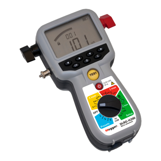
Page 10: Dlro-H200 Overview
3 DLRO-H200 OVERVIEW DLRO-H200 overview 3.1 The instrument 10 11 Top view Bottom view DLRO-H200 ZP-BD04E BD0472CE... - Page 11 3 DLRO-H200 OVERVIEW Current output terminal (-) Function selector Current output terminal (+) 0.1 s Test positions Protective conductor terminal 0.6 s Measurement time with Display minimum current guaran- ▪ The display offers a combination of analogue arc and a 0.1 s...
-
Page 12: Included Accessories
3 DLRO-H200 OVERVIEW 3.2 Included accessories ▪ Test cables with Kelvin probes (one with trigger) Test cables with Kelvin clamps ▪ Transport case ▪ Charger Belt clip (50-11010) ▪ Rubber holster ▪ Carrying strap ▪ Belt clip ▪ DLRO-H200 Win (GA-90000) Test cables with Kelvin probes (incl. -
Page 13: Optional Accessories
Current cable 0.5 m (1.6 ft), Connection plate and sense cables 15 m (49 ft), Ground cable GA-00384 Calibration kit BD-90002 Soft carrying case For DLRO-H200, Charger and Cables GD-00620 Cable kit 5 m, (GA-00380) (BD-90002) Calibration kit (GD-00620) Soft carrying case... -
Page 14: Functions And Set Up
The instrument should be in the OFF position when not in use. Note The DLRO-H200 will go to stand by mode af- ter about 10 minutes of inactivity. To wake up, press Stand-by / Wake up (CLR LOG) button. DLRO-H200... -
Page 15: Bluetooth
Turn the function selector to the PC COM position on the DLRO-H200 panel. Set-up PC Start the DLRO-H200 Wi. The software shall Set-up headset now read out the s/n on the DLRO-H200 and Paired the connected port. Enable / Disable (headset) Enabled (headset) -
Page 16: Clock
Setup / Press ▶ or ◀ to return. There are three functions in this position: Set date and time. Set volume for the internal buzzer. Discharge the DLRO-H200 internal capacitor, (used for service only). Display abbreviations Clock Volume Discharge (used for service only) -
Page 17: Minimum Current - I Nom
In this case it is the minimum cur- rent showing "> 037 A". The measurements are numbered in numerical order (1 to 1999) Measurement is automatically stored, provided that the memory is not full. BD0472CE ZP-BD04E DLRO-H200... -
Page 18: Pass/Fail - P/F
Use the keys ▶ ◀ to select the digit to change, it will blink. Use the keys ▲ ▼ keys to set the desired value. Press OK key. To cancel press C key or turn the function selector to another position. DLRO-H200 ZP-BD04E BD0472CE... -
Page 19: Pc Communication - Pc Com
4 FUNCTIONS AND SET UP 4.8 PC communication – PC 4.9 Audio signals The DLRO-H200 emits different sounds to give an au- dible information / confirmation of an event / action. The PC COM position is used for all operations per- The sound is emitted from a built-in buzzer and from formed from a PC using DLRO-H200 Win. -
Page 20: Battery Power Supply
12 regular charge cycles to get the most out of them. ▪ To prevent the batteries from becoming fully discharged, if DLRO-H200 is not used regularly, a good rule of thumb is to charge the batteries every month. DLRO-H200 ZP-BD04E... - Page 21 4 FUNCTIONS AND SET UP Note: If the batteries are fully discharged it will be impossible to charge them in the DLRO-H200. However, a separate battery charger may be able to charge the batteries. BD0472CE ZP-BD04E DLRO-H200...
-
Page 22: Operating Instructions
Important safety regulations. Power supply Prepare testing by charging the batteries se section 4.10 Battery power supply. Note The DLRO-H200 cannot be used for testing Warning during battery charging. See section 5.8 Troubleshooting LCD display Pass/Fail indicator The display can be backlighted by pressing the key In this case the Pass/Fail is set to 100 μΩ... -
Page 23: Working At Low Temperatures
Saved results can be recalled by scrolling to Working at low temperatures desired label using the ▲ ▼ keys. DLRO-H200 can be operated down to -20°C provided that the batteries keep a temperature over 0°C. When Delete results in the log the instrument is in use the batteries will generate Select label using the ▲ ▼... -
Page 24: Measurement With Max. Charge, I=I Max
The DLRO-H200 is ready for a measurement when the lock symbol disappears. Ready for test Press the TEST button on DLRO-H200 or the pull the trigger on the probe. A continuous audio signal tells that the measurement is in progress. -
Page 25: Measurement With Minimum Current Guarantee, I > I Nom
Charging When the lock symbol disappears the DLRO- H200 is ready for a measurement. Ready for test Press the TEST button on DLRO-H200 or Trig- ger on the probe. A continuous audio signal tells that the measurement is in progress. -
Page 26: Measurement Using P/F - Pass/Fail
The character ">" to the left of the big digits indicates that the P/F value was exceeded. Press the TEST button on DLRO-H200 or the pull the trigger on the probe. A continuous audio signal tells that the measurement is in progress. -
Page 27: Measurement With User Defined Settings
See section 4.6 Data logger – LOG for how to set up. tings. These can only be set via a PC with the DLRO- Running numbers mode H200 Win Software, see chapter DLRO-H200 Win. The measurements are numbered in numerical order 1 to 1999 Measurement is automatically stored, provided that the memory is not full (Running numbers =1999). - Page 28 By using the ◀ ▶ and ▲ ▼ keys you can toggle be- tween the saved test results The display shows "3" for the third measurement for the specific label. The arrow sign to the left only represents the omitted characters to the left of the digit "3". DLRO-H200 ZP-BD04E BD0472CE...
-
Page 29: Measurement Using P/F And I Nom
< current limit and > P/F limit. Ready for test Press the TEST button on DLRO-H200 or pull the trigger on the probe. A continuous audio signal tells that the measurement is in progress. -
Page 30: Testing On Circuit Breakers Having A Current Transformer In The Loop
Problem Solution transformer in the loop Headset does not Check that it is paired to DLRO-H200 work Check on DLRO-H200 that Bluetooth is enabled If there is a current transformer (CT) in series with the breaker contact to be tested then it is advisable to make... - Page 31 6 APPLICATION EXAMPLES BD0472CE ZP-BD04E DLRO-H200...
-
Page 32: Application Examples
If you are measuring resistance in a circuit Attach the test cables with Kelvin probes (2 x breaker or disconnecting switch (isolator), 1.3 m) one with a trigger, to DLRO-H200. make sure that it is closed and grounded at both sides before testing. -
Page 33: Test A Cb Using Dualground
CB's grounding cable is attached. the instrument. (the opposite side of CB from where the ex- Hook the DLRO-H200 to your belt or use the tra ground cable is attached). strap to hang it around your neck. Mount the 0.1 m plate to the current out... -
Page 34: Dlro-H200 Win
7 DLRO-H200 WIN DLRO-H200 Win 7.1 Introduction 7.2 DLRO-H200 Win installation DLRO-H200 Win is a Windows® program that com- municates with the DLRO-H200 micro-ohmmeter instrument. Preconditions It is used for: ▪ Windows XP / 7 / 10 ▪ Reading measurement data from the instrument and save it to file ▪... -
Page 35: Start Dlro-H200 Win
Turn the function selector to the PC COM position on the DLRO-H200 instrument. At program startup the SW will try to connect to DLRO-H200 using the same COM port that the last successful connection used. If there have been no previous DLRO-H200 connections from this computer the SW will scan all available COM ports. - Page 36 Click the button “Scan for DLRO-H200”. H200” button the PC system time is written to the The operation can be interrupted with the DLRO-H200. This is the easiest way to set the clock in “Cancel scan” button. DLRO-H200, see Figure 8.4.3 Figure 7.3 The Connection settings window, searching.
-
Page 37: Read The Measurement Log
7 DLRO-H200 WIN 7.5 Read the measurement Click the "Measurements" button on the Start page or select "Measurements" from the "Tools" menu. Figure 7.5 Data dumping dialog. Click on the "Retrieve all data" button to download all measurements stored in the instrument. -
Page 38: Export Data To File
7 DLRO-H200 WIN Figure 7.7 Data dumping finished. The columns can be sorted by clicking the headers and arranged by click-hold and drag. Export data to file Click the "Save to file" button (this button is not enabled if the list is empty). -
Page 39: User Settings
Type the value in the U reference column in DLRO-H200 Win Click the "Measure" button next to the field. The value measured by the DLRO-H200 will then be propagated to the "U measured" text field. New calibration factors will automatically be calculated. -
Page 40: Ammeter Calibration
Connect the current cables from the DLRO- factory you can save it to the DLRO-H200. H200 to the reference shunt Click the"Save to instrument" button. Connect separate sense leads from the DLRO-... - Page 41 7 DLRO-H200 WIN Figure 8.7.5 Calibration report. BD0472CE ZP-BD04E DLRO-H200...
-
Page 42: Specifications
8 SPECIFICATIONS Specifications SPECIFICATIONS DLRO-H200 Measurement section Specifications are valid at fully charged batteries and an ambient Minimum current Selectable 50 A / 100 A temperature of +25°C, (77°F). Specifications are subject to change guarantee Valid at resistance ≤2mΩ without notice. - Page 43 BD0472CE ZP-BD04E DLRO-H200...
- Page 44 Safety instructions ........... 6 Included accessories ........12 Save test results ..........23 Input for sensing voltage (-) ......11 Service and support......... 8 Input for sensing voltage (+) ......11 set up ............. 14 Specifications ..........42 DLRO-H200 ZP-BD04E BD0472CE...
-
Page 45: Index
Test positions ..........14 To choose I > I nom or I = I max ....... 22 To choose measurement time ....... 22 Training courses ..........8 Trouble shooting ..........30 USER – 1/2/3 ..........14 Wake up ............11 BD0472CE ZP-BD04E DLRO-H200... - Page 46 INDEX DLRO-H200 ZP-BD04E BD0472CE...
- Page 48 Your “One Stop” Source for all your Megger Group Limited UNITED KINGDOM electrical test equipment needs Dover, Kent CT17 9EN ▪ Battery Test Equipment ENGLAND ▪ ▪ AUSTRALIA POLAND ▪ Cable Fault Locating Equipment ▪ ▪ BULGARIA ROMANIA ▪ Circuit Breaker Test Equipment ▪...
Need help?
Do you have a question about the DLRO-H200 and is the answer not in the manual?
Questions and answers