Megger Ducter DLRO2 User Manual
Low resistance ohmmeter 2 a
Hide thumbs
Also See for Ducter DLRO2:
- Quick start manual (12 pages) ,
- Quick start manual (40 pages) ,
- User manual (54 pages)
Table of Contents
Advertisement
Advertisement
Table of Contents

Related Manuals for Megger Ducter DLRO2


Summary of Contents for Megger Ducter DLRO2
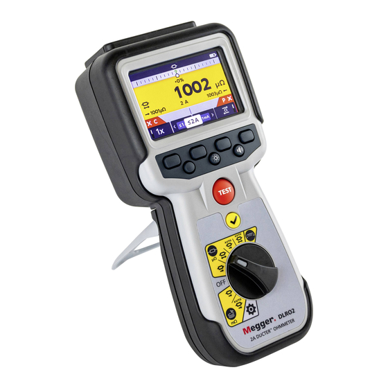
- Page 1 DLRO2 Ducter™ Low Resistance Ohmmeter 2 A User Guide...
- Page 2 Megger Ltd reserves the right to alter the specification of its products from time to time without notice. Although every effort is made to ensure the accuracy of the information contained within this document it is not warranted or represented by Megger Ltd. to be a complete and up - to - date description.
- Page 3 Directive 2014/53/EU. Other equipment manufactured by Megger Instruments Limited described in this user guide is in compliance with Directives 2014/30/EU and 2014/35/EU where they apply. The full text of Megger Instruments EU declarations of conformity are available at the following internet address: megger.com/company/about-us/eu-dofc www.megger.com...
-
Page 4: Table Of Contents
4.2.3 Battery options ............................15 5. Tests, Inductive mode ........................16 Manual stop ............................. 16 5.1.1 First test ..............................16 5.1.2 Second test ............................17 Auto stop ..............................18 5.2.1 First test ..............................18 5.2.2 Second test ............................19 DLRO2 www.megger.com... - Page 5 10.3.4 Battery error screens ..........................32 10.4 Battery Replacement ..........................33 10.4.1 Replace batteries and remove isolation tab ................... 34 11. Specifications ..........................35 12. Accessories and Equipment ......................37 12.1 Included Accessories ..........................37 12.2 Optional Accessories..........................37 www.megger.com DLRO2...
- Page 6 Contents 13. Calibration, Repair and Warranty ....................38 13.1 Return procedure ..........................38 14. Decommissioning ........................39 14.1 WEEE Directive ............................39 14.2 Battery disposal ............................. 39 15. Notes ............................40 DLRO2 www.megger.com...
- Page 7 Contents www.megger.com DLRO2...
-
Page 8: Introduction
Introduction 1. Introduction This user guide details the operational and functional details of the Megger DLRO2 Ducter Low Resistance Ohmmeter 2 A. Please read this user guide fully before attempting to use the DLRO2. Product Description The DLRO2 is a tough and truly hand held 2 A low resistance ohmmeter, designed to provide fast, accurate and repeatable measurements even in electrically noisy environments. -
Page 9: Applications
PDU boards, lightning protection systems, final circuits. www.megger.com DLRO2... -
Page 10: Company Web Site
Introduction Company web site Occasionally an information bulletin may be issued via the Megger web site. This may concern new accessories, new usage instructions or a software update. Please occasionally check on the Megger web site for anything applicable to your Megger instruments. -
Page 11: Safety Warnings
Protection provided by the instrument may be impaired if it is not used in a manner specified by the manufacturer. The voltage warning function will operate only if the instrument is switched on and working correctly. „ In the absence of an indication do not assume that there are no hazardous voltages. www.megger.com DLRO2... -
Page 12: Test Lead Safety Warnings
Circuit connections, exposed conductive parts and other metalwork of an installation or equipment under test must not be touched during testing. Only Megger approved test leads with right-angled instrument connectors must be used with this instrument. „ Test leads must be at least 1 m in length and provide a total loop impedance ≥ 26 mΩ. -
Page 13: Safety, Hazard And Warning Symbols On The Instrument
NOTE: The warning will not operate if the instrument is set to OFF. Internal Error Warning Internal Error Warning. To clear the error, switch the instrument OFF and then back ON. Contact Megger if this does not clear the error. Read the User Guide Refer to the user guide if this message shows. -
Page 14: Instrument Controls
Refer to 3.4.1 External electrical connections of DLRO2 on page 11 Display Battery cover Soft keys (multifunction) Stand Has no function on this model Back-light control Has no fucntion on this model Test TICK button Rotary selection switch DLRO2 www.megger.com... -
Page 15: Instrument Display
Soft keys functions (dependant on rotary selection switch position) Latest result Secondary field Battery condition indicator C continuity indicator Noise indicator Forward measurement result Units of measure (for latest result) Unidirectional or bidirectional selection Reverse measurement result Inductive charge warning www.megger.com DLRO2... -
Page 16: Instrument Rotary Control
Instrument Controls Instrument Rotary Control Item Description Item Description Rotary switch positions Inductive mode Long leads mode Resistance mode Settings mode (grey) Off position DLRO2 www.megger.com... -
Page 17: Instrument Connections And Leads
3.4.1 External electrical connections of DLRO2 Slider to front Slider to back Item Description Item Description Rear attachment point for strap Slider in rear position Slider in front position Battery charger connection Connections: C1, P1, P2, C2 USB port (firmware update) Front www.megger.com DLRO2... -
Page 18: The Difference Meter
/ solid circle for previous initial reference measurement result. Reference measurement, green Note: All markers are positioned in chronological order. The most recent is positioned high on the Difference Meter line, the oldest is positioned lowest. DLRO2 www.megger.com... -
Page 19: Difference Meter Example Of Operation
The 1000% difference shows clearly that something isn’t right. Check the leads, connections, unit under test, etc. Note: The units on the main display have changed from µΩ to mΩ and are now indicated in blue to highlight the change. www.megger.com DLRO2... - Page 20 Fifth measurement is made, the Difference Meter shows it’s result, relative to the reference measurement. This reading is now just -1% lower than the reference measurement. Note: The units remained unchanged as µΩ and are shown in black. DLRO2 www.megger.com...
-
Page 21: Setting Up The Dlro2
240 V AC. Ensure the correct battery type is selected in the setting menu. Charging will only occur if the battery type is set to NiMH. Refer to 9. Settings on page 28. Warning: Charge NiMH cells only between 0 ºC and 40 ºC ambient temperature. www.megger.com DLRO2... -
Page 22: Tests, Inductive Mode
C and P indicators show red background with for no continuity or green background with for good continuity. Proceed when both show . The continuity indicators are active during the test and will update if continuity changes. DLRO2 www.megger.com... -
Page 23: Second Test
Do not remove the test leads until discharge is complete and the warning disappears. Note: If continuity is lost from either the C or P connection during a test, this screen will be displayed for 3 seconds. The DLRO2 will then return to the start of the test. www.megger.com DLRO2... -
Page 24: Auto Stop
C and P indicators show red background with for no continuity or green background with for good continuity. Proceed when both show . The continuity indicators are active during the test and will update if continuity is lost. DLRO2 www.megger.com... -
Page 25: Second Test
) will flash on the left of the screen and an audible warning buzzer will sound. Do not remove the test leads until discharge is complete and the warning disappears. Note: The TICK button ( ) will set a new reference value. www.megger.com DLRO2... -
Page 26: Tests, Resistance Mode
When continuity is detected on both circuits, the C and P indicators will both be greyed out and the test will start automatically. If required, to stop the test press the TEST button. DLRO2 www.megger.com... -
Page 27: Post Auto-Start, Unidirectional Test
C and P continuity indicator will turn grey. This indicates the C or P lead must be disconnected and reconnected to restart the test. Alternatively press the TEST button to start another test. Continuity on C or P has been lost. Re-establish continuity to start a new test. www.megger.com DLRO2... -
Page 28: Manual, Bidirectional / Unidirectional Resistance Mode
C and P indicators show red background with for no continuity or green background with for good continuity. Proceed when both show 4. To start the test press the TEST button. If required, to stop the test press the TEST button. DLRO2 www.megger.com... -
Page 29: For A Unidirectional Test
‘Two previous results’ in the secondary screen, left is previous result and right is the result before that. To stop the test press the TEST button. If continuity is maintained, pressing the TEST button will start a new test www.megger.com DLRO2... -
Page 30: Tests, Long Leads Mode
2. Connect C1-C2 and P1-P2 to the instrument and the unit under test. C and P indicators show red background with for no continuity or green background with for good continuity. DLRO2 www.megger.com... -
Page 31: For Manual Mode
The dashes (or an old result) will flash until a new result is displayed. On the secondary display dashes or previous results will flash until a new result is ready. The test will run automatically. If required, to stop the test press the TEST button or break continuity. www.megger.com DLRO2... - Page 32 If the test has been stopped by the TEST button the continuity indicators will be grey. If continuity already is shown on the C and P connectors press the TEST button to re-start the test. DLRO2 www.megger.com...
-
Page 33: Error And Warning Conditions
2. Error text, fuse failure. The fuses in DLRO2 are not user replaceable. If this error screen appears the instrument must be returned to Megger for repair. Refer to 13. Calibration, Repair and Warranty on page 38. 8.2.3 Error screen B 1. -
Page 34: Settings
Settings 9. Settings In this section various user settings can be adjusted or accessed. Megger DLR02 icons General settings Switch the rotary switch to the settings mode . µ µ Go to the general settings tab Use soft key 2 to select required setting as listed below. -
Page 35: Language Settings
Turn OFF. Wait 3 seconds and turn back ON. 2. The boot loader screen will be displayed when the instrument starts up. 3. Press [OK] to upgrade firmware or [TEST] to cancel. 4. The will progress through various stages. www.megger.com DLRO2... - Page 36 6. Restart the DLRO2 (turn off and on). 7. If a measurement firmware update is to be performed, then the measurement firmware update screen will display. At the end of the firmware update, the instrument will automatically restart. DLRO2 www.megger.com...
-
Page 37: Maintenance
When the battery is charging, it will show an animation of the battery from empty to full, then repeats. Once the battery is full, the animation stops. The maximum charging time for NiMH batteries is 6 hours, normal charging time is approximately 4 hours. www.megger.com DLRO2... -
Page 38: Supply
10.3.2 Battery Charging When charging NiMH rechargeable batteries, only use the power supply provided by Megger. Other power supplies will not function with the DLRO2. The Megger power supply is designed to preserve the functions and accuracy of the DLRO2. -
Page 39: Battery Replacement
Battery Replacement Warning: Remove all test leads before removing the battery cover. Caution: Batteries should not be left in the instrument if remaining unused for an extended period. Description Quantity Screw, captive Cover, battery Battery isolation tab Batteries www.megger.com DLRO2... -
Page 40: Replace Batteries And Remove Isolation Tab
7. Replace the battery cover (2) in reverse order to above. 8. Re-secure with screw (1). 9. If the type of batteries has changed (NiMH or Alkaline) ensure the battery technology setting is changed. Refer to 9. Settings on page 28. DLRO2 www.megger.com... -
Page 41: Specifications
24.000 Ω 10.0 mA 0.001 Ω 200.00 Ω 10.0 mA 0.01 Ω 30.000 Ω 1.00 mA 0.001 Ω 240.00 Ω 1.00 mA 0.01 Ω 2000.0 Ω 1.00 mA 0.1 Ω www.megger.com DLRO2... - Page 42 4 X 4 mm shrouded sockets Data: USB (For firmware updates only) User may update instrument firmware to latest version themselves Battery charger: 2.5 mm DC jack connector LANGUAGES User Interface: English, French, German and Spanish User guide: English, French, German and Spanish DLRO2 www.megger.com...
-
Page 43: Accessories And Equipment
10 A Fused test probe and clip lead set 1011-673 DLRO2 current and potential leadset 2m. 2 x red lead, 2 x blk lead, 2 x grabber clip, 2 x probe Full calibration certificate DLRO2 1013-170 1013-169 UKAS calibration certificate DLRO2 www.megger.com DLRO2... -
Page 44: Calibration, Repair And Warranty
3. Pack the instrument carefully to prevent damage in transit. 4. Before the instrument is sent to Megger, freight paid, make sure that the returns label is attached or that the RA number is clearly marked on the outside of the package and on any correspondence. For items being returned outside of the UK and USA please send copies of the original purchase invoice and packing simultaneously by airmail to expedite clearance through customs. -
Page 45: Decommissioning
14.1 WEEE Directive The crossed out wheeled bin symbol placed on Megger products is a reminder not to dispose of the product at the end of its life with general waste. Megger is registered in the UK as a Producer of Electrical and Electronic Equipment. The Registration No is WEE/ HE0146QT. -
Page 46: Notes
Notes 15. Notes DLRO2 www.megger.com... - Page 47 Kent CT17 9EN ENGLAND +44 (0)1 304 502101 +44 (0)1 304 207342 Manufacturing sites Megger Limited Megger GmbH Megger USA - Valley Forge Archcliffe Road Obere Zeil 2 61440 Valley Forge Corporate Center Dover Oberursel, 2621 Van Buren Avenue Kent...
Need help?
Do you have a question about the Ducter DLRO2 and is the answer not in the manual?
Questions and answers