Table of Contents
Advertisement
Quick Links
Advertisement
Table of Contents

Related Manuals for Megger 1006-603


Summary of Contents for Megger 1006-603
- Page 1 DLRO10HD 10 A Digital Low Resistance Ohmmeter USER GUIDE...
-
Page 2: Safety Warnings
If it is impossible to de-energise the circuit, (e.g. high voltage batteries cannot be switched off while their connections are tested) the user must be aware of the dangers. The instrument terminals will become live when connected to the circuit. Therefore when used on hazardous voltages the optional Megger terminal cover (part number 1002-390) must be used. - Page 3 Inspection Before each use of the instrument, visually inspect the instrument case, test leads and connectors to confirm that their condition is good, with no damaged or broken insulation. Charging and mains/line operation In normal circumstances the instrument is completely safe. However, in case of an unforeseen emergency ensure instrument is positioned to allow fast disconnection of mains/line plug.
-
Page 4: Table Of Contents
Contents Safety warnings Symbols used on the instrument General description Application Caution: Refer to accompanying notes Test modes HV warning Warning messages Equipment protected throughout by Double or reinforced Test techniques and applications Insulation (Class II) General operation Equipment complies with current EU Directives Electrical specifications General specifications Equipment complies with ‘C tick’... -
Page 5: General Description
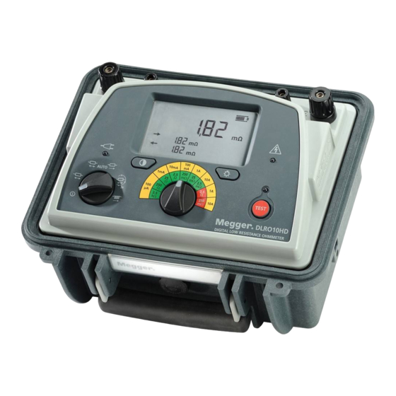
General description The Megger DLRO10HD enhances Megger’s existing family of 10 Amp DC current is passed through the unit under test in both directions and the low resistance ohmmeters (DLRO10 and DLRO10X). This heavy duty model resulting resistance averaged. If a user wants to make a series of quick tests... -
Page 6: Application
Applications The DLRO10HD measures low resistance values in applications ranging from Metal alloys, welds and fuse resistance ■ railways and aircraft to resistance of components in industry. Any metallic Graphite electrodes and other composites ■ joint can be measured but users must be aware of measurement limitations depending on application. -
Page 7: Test Modes
Test modes Test mode, is selected by a six (including off) positioned rotary selector selected current through the sample continuously in one direction only. The switch that activates the following modes: instrument will take repetitive readings, which will gradually decrease to the true value as the voltage stabilises. -
Page 8: Warning Messages
Warning Messages Noise Noise in excess of 100 mV 50/60 Hz will activate the noise icon that will flash and no result will be displayed. ‘C’ & ‘P’ Indicators A good measurement requires both the current carrying circuit and the voltage detection circuit to be completed by the unit under test. -
Page 9: Test Techniques And Applications
TEST TECHNIQUES AND APPLICATIONS TESTING USING DH4-C DUPLEX HANDSPIKES In-line connector with indicator lamps when used with DLRO10HD Each handspike is marked with the letter P. This indicates the potential terminals. These should be the ‘inside’ contacts when making a Lamp L1 Lamp L2 Meaning... -
Page 10: General Operation
GENERAL OPERATION DLRO10HD Out of the Box Measurement terminals First connect the test leads to their respective measurement terminals. To simplify lead connection to the DLRO10HD the lid can be removed by lifting it to approximately 45º from closed position and sliding it to the right. Connect line power lead if line power is available. - Page 11 LCD Icons After starting a test the user will see confirmation of successful continuity testing on the LCD. If the dashes are not shown connecting 1 & 2 C and/or P leads connection has not been detected. Battery icons with battery charge level indicator C 1---2 Line power connected P 1---2...
- Page 12 Power Lead and Battery Charging Battery Charge indication If the power lead supplied is not suitable for your mains connection, do not use an adaptor. Always use a power lead fitted with the correct plug. Full battery The instrument is fitted with a two-pin IEC60320 power inlet. Most power leads are made with three-core cable, so the ground connection will not Battery low be used.
-
Page 13: Electrical Specifications
Electrical specifications Resistance/Current Ranges The green resistance ranges on the keypad indicate low output power (<0.25 W) outputs. Red ranges indicate higher 2.5 W (1 A) and 25 W (10 A) power outputs. Resolution and Accuracy Test current accuracy ±10% Voltmeter input impedance >200 kΩ... -
Page 14: General Specifications
-10 °C to +50 °C (14 °F to 122 °F) <90% RH Battery type 6 V, 7 Ah sealed lead acid (return instrument to a Megger authorised Reference conditions 20 ºC ±3 ºC repair agent for replacement) Storage temperature... -
Page 15: Accessories
Although the terminal cover may be used with any test leads, only Duplex handspikes with replaceable Needle Points Megger DH4 and DH5 duplex handspikes have 2m/7ft 242003-7 suitable probe insulation to comply with the Duplex 1.27 cm (1⁄2”) Kelvin Clips. -
Page 16: Repair And Warranty
Note: Any unauthorised prior repair or adjustment will automatically 9m/30ft 242021-30 invalidate the Warranty. Current clips (2) for current connections. Instrument Repair and Spare Parts 2m/7ft 242041-7 For service requirements for Megger Instruments contact:- 5.5m/18ft 242041-18 Megger Limited 9m/30ft 242041-30 Megger Archcliffe Road... - Page 17 A number of independent instrument repair companies have been approved for repair work on most Megger instruments, using genuine Megger spare The crossed out wheeled bin placed on the Megger products is a reminder parts. Consult the Appointed Distributor / Agent regarding spare parts, not to dispose of the product at the end of it’s product life with general...
- Page 18 Megger Instruments Limited described in this user guide is in compliance with Directive 2014/53/EU. Other equipment manufactured by Megger Instruments Limited described in this user guide is in compliance with Directives 2014/30/EU and 2014/35/EU where they apply. The full text of Megger Instruments EU declarations of conformity are...
- Page 19 Other technical sales offices Toronto - Canada, Sydney - Australia, Mumbai - India, Madrid - Spain and the Kingdom of Bahrain. Megger products are distributed in 146 countries worldwide. This instrument is manufactured in the United Kingdom. The company reserves the right to change the specification or design without prior notice.
Need help?
Do you have a question about the 1006-603 and is the answer not in the manual?
Questions and answers