Table of Contents
Advertisement
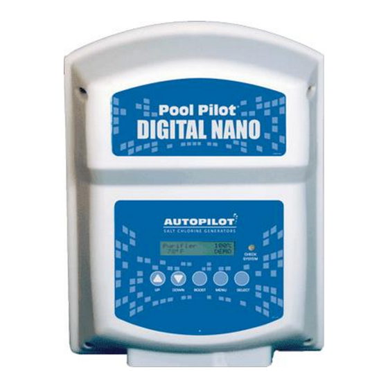
Digital Nano/Nano
Digital Nano
Digital Nano + Models:
INSTALLER: This Document is Purchaser's Property and is to remain with the Equipment Owner
Pool Pilot
Models:
75040, 75040-xx, 75041 and 75041-xx
Manifold:
94105
Cell:
RC35/22
75042, 75042-xx, 75043 and 75043-xx
Manifold:
94106
Cells:
RC35/22 or RC28
®
Owner's Manual
Installation / Operation
This manual covers the installation
and operation of Digital Nano and
Digital Nano + Chlorine Generators
Important!
Read This Manual And Product
Labels Before Installing Or
Operating This Equipment
LTP0086 Rev-1C 07/28/2015
+
Advertisement
Table of Contents

Related Manuals for Aquacal Pool Pilot Digital Nano


Summary of Contents for Aquacal Pool Pilot Digital Nano
- Page 1 Pool Pilot ® Digital Nano/Nano Digital Nano Models: 75040, 75040-xx, 75041 and 75041-xx Manifold: 94105 Cell: RC35/22 Digital Nano + Models: 75042, 75042-xx, 75043 and 75043-xx Manifold: 94106 Cells: RC35/22 or RC28 Owner’s Manual Installation / Operation This manual covers the installation and operation of Digital Nano and Digital Nano + Chlorine Generators Important!
-
Page 2: Table Of Contents
TABLE OF CONTENTS SECTION 1 - FACTORY CONTACT INFORMATION................... 1 SECTION 2 - SAFETY INFORMATION ........................ 1 SECTION 3 - OWNER QUICK START & RUN ..................... 3 3.1 How Your Digital Nano/Nano + Works ......................3 3.2 Control Overview ............................4 3.2.1 Up and Down Arrows ........................ - Page 3 TABLE OF CONTENTS 7.6 Review of Installer, Owner, & Maintenance Menu Programming ..............19 7.6.1 Pool Volume ..........................19 7.6.2 Calibrating Salt ........................... 19 7.6.3 Select Language ........................19 7.6.4 Calibrating Temperature ......................20 7.6.5 Select Units ..........................20 7.6.6 Temperature ..........................20 7.6.7 Set Reverse Time ........................
-
Page 4: Section 1 - Factory Contact Information
SECTION 1 - FACTORY CONTACT INFORMATION If you should need to call AquaCal AutoPilot, Inc. for questions, services, or parts, please have your model and serial numbers available. Please also have the name of your installer and date of your equipment’s installation. - Page 5 CAUTION - Failure to heed the following may result in equipment damage. The AquaCal AutoPilot Digital Nano/Nano + must be installed and operated as specified. Failure to do so will void the equipment warranty. To permit proper air circulation, the Digital Nano/Nano + must be mounted at least 1-foot (30 cm) above ground level or any other cooling obstruction.
-
Page 6: Section 3 - Owner Quick Start & Run
Page 3 conditions. Equipment damage due to freezing conditions is NOT covered under the equipment warranty. Do not use a pool cleaner or vacuum head with wheels, as wheels can leave track marks on newly-plastered pools. Do not allow Granular salt to pile up in one location, without brushing, as staining may occur. -
Page 7: Control Overview
Page 4 3.2 CONTROL OVERVIEW The following is a brief explanation of owner or operator control options. For full features of the Owner Options Menu, please see page 19. The MENU button is pressed to obtain access to the Owner Options Menu. -
Page 8: Normal Display
Page 5 Flashes when water temperature exceeds 125°F, or drops below 10°F Note: When enabled, an audio alarm will sound due to any of the above three (3) conditions. If water flow ceases (or falls below minimum acceptable levels) the alarm will automatically silence after 10 minutes. -
Page 9: Section 4 - Specification And Approvals
Page 6 SECTION 4 - SPECIFICATION AND APPROVALS 4.1 SPECIFICATIONS SPECIFICATION 75040, 75040-XX 75041, 75041-XX 75042, 75042-XX 75043, 75043-XX 110-120 Vac 220-240 Vac 110-120 Vac 220-240 Vac Input Power 2.0 A 1.0 A 2.0 A 1.0 A Maximum Chlorine Output RC35/22 0.8 lb. -
Page 10: Section 5 - Features
Page 7 SECTION 5 - FEATURES Patented temperature compensation for chlorine output control. Programmable microprocessor control. Multi-language digital display (English, Spanish, French and either Italian or Czech). Digitally controlled power to the cell. Tri-Sensor circuitry to monitor water flow, water temperature, and salt level. Calculates and provides recommended salt addition amounts required to maintain the recommended 3000 ppm (mg/L) salt concentration level. -
Page 11: Automatic-Flow Bypass Manifold Assembly (#94105 And #94106)
Page 8 5.2.1 Automatic-Flow Bypass Manifold Assembly (#94105 and #94106) This AquaCal AutoPilot patented manifold is connected into the plumbing after all other equipment. Water from the pool/spa is moved though the manifold by the circulation pump. This patented manifold uses four key components: ... -
Page 12: Section 6 - Maintenance
Page 9 SECTION 6 - MAINTENANCE 6.1 FUSE LOCATION AND RATINGS WARNING - Failure to heed the following may result in permanent injury or death. ELECTRICAL SHOCK HAZARD – Turn off the electrical power to unit before servicing. To inspect or service fuse, disconnect power and remove power center cover (see below for location of fuse). -
Page 13: Removing / Inspecting / Cleaning Tri-Sensor
Page 10 6.2 REMOVING / INSPECTING / CLEANING TRI-SENSOR 6.2.1 Tri-Sensor Assembly Overview The Tri-Sensor Assembly is used to measure water flow, salt level, and water temperature. Note: The use of high strength magnet devices in the close proximity of the Tri-Sensor can cause the flow switch to function incorrectly. -
Page 14: Cleaning Tri-Sensor
Page 11 6) Inspect the two salt sensor blades. The blades should not have any mineral deposits (scale) or other debris on them. 7) Do not use any metallic objects to scrape the blade surfaces or you will remove or damage the blade sensor coating. -
Page 15: Servicing The Cell
Page 12 9) The Digital Nano/Nano + should detect a low water flow at the Tri-Sensor, and activate the red “Check System” light. The Digital Nano/Nano + will also display the message “Chlorine off Check flow.” 10) If the Digital Nano/Nano + did not display this warning, check the Tri-Sensor cable connections and inspect and clean the Tri-Sensor as outlined on page 11. -
Page 16: Manual Cleaning
Page 13 2) White flaky or crusty calcium build up on the edge or between the blades will shorten the life of the cell. If required, clean the cell immediately, and determine the cause of scaling. See “Basic Water Chemistry,” and “Using the Saturation Index”. 6.3.3 Manual Cleaning WARNING - Failure to heed the following may result in permanent injury or death. -
Page 17: Winterizing
Page 14 4) The cell cable has three (3) electrical contact terminals. The cell will have two (2) electrical terminals. Position the cell plug so the two (2) open holes align with two mating terminals and push gently, but firmly, to connect. Use the red weather plug (supplied) to seal the unused contact in the cable. -
Page 18: Section 7 - Programming
Page 15 SECTION 7 - PROGRAMMING 7.1 CONTROL PANEL 7.1.1 Button Overview CHECK SYSTEM LIGHT: Push UP or DOWN arrow to Red LED flashes to warn do the following: attention is required. Sets Chlorine Level %* A warning message will ... -
Page 19: Menus
Page 16 7.2 MENUS Owner Options Test Pool Pilot Select Language Salt Main Menu Select Units Salt Needed Test Pool Pilot Temperature Unit Temperature View Setup Audio Alarm Cell V/A Owner Options End Menu Mode Amp Hrs Maintenance Menu Installer Menu Maintenance Menu View Setup End Menu Mode... -
Page 20: Boost Or Super Boost
Page 17 7.3.2 Boost or Super Boost The Boost feature is used to increase the chlorine % from its normal setting to 100% for a cumulative 24 hour or 72 hour period. When the Boost period expires or is manually terminated the chlorine % returns to its previous setting and normal operation. -
Page 21: Test Pool Pilot (Diagnostic Menu)
Page 18 For the Free Chlorine adjustment, use the following table for fine-tuning the controller output percentage (%): CHLORINE % IF FREE CHLORINE IS LOWER THAN IF FREE CHLORINE IS HIGHER THAN CURRENTLY IDEAL RANGE… IDEAL RANGE… SET TO: The chlorine % output needs to be The chlorine % setting is too high. -
Page 22: Review Of Installer, Owner, & Maintenance Menu Programming
Page 19 “##,### gallons (liters)” (The pool volume programmed in Installation Menu; 15,000 is the factory setting) “Reverse = # hrs.” (The reverse rate programmed in Installation Menu: 4 hrs. is factory setting) “Temp. adjust = #” (The temperature adjustment variation of actual Tri-Sensor reading; page 20) ... -
Page 23: Calibrating Temperature
Page 20 7.6.4 Calibrating Temperature Note: Temperature can only be calibrated 2 minutes after start-up. Used only when it is desired to match the display of the Digital Nano/Nano + to another on-site thermometer. until “Maintenance Menu” is displayed; then press SELECT. 1) Press MENU;... -
Page 24: Force Reverse
Page 21 7.6.9 Force Reverse: Note: this is a diagnostic tool, only, and should not be used unless a problem is suspected. Program the cell to activate a force reverse cycle and verify if the system is reversing polarity (self- cleaning). -
Page 25: Section 8 - Installation
Page 22 SECTION 8 - INSTALLATION 8.1 BASIC SYSTEM OVERVIEW The Digital Nano/Nano + is a salt chlorination system for pool or spa purification, and is designed to operate in the following configurations: SHOWN WITH AUTOMATIC-FLOW BYPASS MANIFOLD ASSEMBLY (#94105 or #94106): GFCI Optional Circuit... -
Page 26: Before Installing
Page 23 8.2 BEFORE INSTALLING Determine everything needed for installation is on hand. Determine where the Manifold Assembly will be plumbed. Identify a suitable mounting location for the Digital Nano/Nano + within proper cord length to the manifold. -
Page 27: Installation Steps
Page 24 8.4 INSTALLATION STEPS Details on each step of the installation process are presented on the following pages: 1) Plumbing the Manifold Assembly (page 24) 2) Mounting the Digital Nano/Nano + (page 25). 3) Electrical Requirements & Connections (page 26). a) Grounding and Bonding b) AC Input Voltage Wiring (Digital Nano/Nano + to an external timer or controller) c) Low Voltage Wiring... -
Page 28: Mounting The Digital Nano/Nano
Page 25 STEP-2: The manifolds will accept the following cells: CAUTION - Failure to heed the following may result in equipment damage. The Digital Nano manifold may only use the RC35/22 cell. MANIFOLD AND CELL COMBINATIONS CHLORINATOR TYPE MANIFOLD NUMBER CELL NUMBER The Digital Nano 94105, 94105M... -
Page 29: Electrical
Page 26 8.7 ELECTRICAL CAUTION - Failure to heed the following may result in equipment damage. Connecting 230Vac to a unit that has been configured to 115 Vac will result in permanent damage to the unit. Damage due to incorrect wiring is not covered under the warranty. -
Page 30: Low-Voltage Cable Connections At Control Center
Page 27 8.7.4 Low-Voltage Cable Connections at Control Center Bonding Lug Directional Tab: Position the tab forward in relation to water flow. Cell Tri-Sensor Cord Assembly Figure 8 8.7.5 Grounding and Bonding Connect the green ground wire to the supply ground. See bonding lug in Figure 8. ... -
Page 31: Preparing The Pool Water
Page 28 8.8 PREPARING THE POOL WATER Installer please note - When properly sized to the site, the Digital Nano/Nano + will meet the sanitizer “maintenance” requirements of the pool/spa. The Digital Nano/Nano + is not designed to chlorine shock treat, or build up a chlorine residual, when starting with a zero or very low chlorine level. -
Page 32: Adding Salt
Page 29 8.8.3 Adding Salt Type of Salt to Add It is important to use Sodium Chloride (NaCl) salt that is greater than 99% pure. Acceptable types of salt include granular food grade, pool salt, water softener pellets, or solar salt flakes; these are usually available in 25 to 60 lb bags (11 to 36 kg) at local pool or building supply outlets. -
Page 33: Programming At Installation
Page 30 8.9 PROGRAMMING AT INSTALLATION The Digital Nano/Nano + requires the pool volume be initially programmed into the installer menu. The control center will then indicate how many pounds (kgs) of salt to add should salt levels fall. The default pool size is 15,000 gallons (56,781 liters). -
Page 34: Section 9 - Troubleshooting
Page 31 SECTION 9 - TROUBLESHOOTING MESSAGE DISPLAYED PROBLEM TYPICAL SOLUTION Cell inspect due This is an advisory The cell has been operating for a while. This is a message. reminder that now would be a good time to remove and inspect the cell and filter screen to see if they need The unit will generate cleaning. - Page 35 Page 32 MESSAGE DISPLAYED PROBLEM TYPICAL SOLUTION No Error Displays Salt level on display The test may have been faulty or the salt strips may does not match pool be old or damaged. Have salt level rechecked at store or salt test strip. local pool store.
- Page 36 The cell cord has a short. Replace. Warning! Temperature is out of Check the Tri-Sensor cable; make sure it is not Bad temp sensor? range. disconnected or loose. Check the water temperature. If confirmed temperature is OK, contact AquaCal AutoPilot for assistance.
- Page 37 Page 34 MESSAGE DISPLAYED PROBLEM TYPICAL SOLUTION Normal display There are no warning The chlorine setting has been fine, but a temporary messages on the boost of chlorine is needed to adjust for rain or a display but the temporary bather increase.
- Page 38 Page 35 MESSAGE DISPLAYED PROBLEM TYPICAL SOLUTION Chlorine display Chlorine locked at 1% If the water temperature is 55°F (10°C) or colder the Pool Pilot has automatically turned the Chlorine output down to 1% to avoid over-chlorination. Bacteria and algae growth is greatly reduced at this temperature, so this should not be a problem.
-
Page 39: Section 10 - Reference
Page 36 SECTION 10 - REFERENCE 10.1 BASIC WATER CHEMISTRY The Digital Nano/Nano + is designed to produce chlorine on a daily basis. To monitor the system’s efficiency, the water chemistry ranges, and schedule of periodic checks should be followed. See “Water Balance &... - Page 40 Page 37 IDEAL EFFECT OF CHEMICAL TEST CORRECTIVE ACTIONS LOW / HIGH LEVELS SCHEDULE Calcium Monthly Low CH: Etching of plaster, equipment Low CH: Add calcium chloride flakes. Hardness corrosion High CH: Scale formation, cloudy water. High CH: Partially drain and refill pool with Rapid buildup of scale may exceed the fresh water to dilute.
-
Page 41: Chlorine
Page 38 10.1.1 Chlorine The desirable form of chlorine is called Free Chlorine. This form of chlorine is responsible for the actual sanitation activity in pools and spas. Free chlorine is highly reactive and once added to pool/spa water has a tendency to combine with organic matter in the pool/spa. It quickly attacks pathogens as well as other bather wastes. -
Page 42: Using The Saturation Index
Page 39 10.2 USING THE SATURATION INDEX This index is used by pool professionals to ensure that your total water chemistry does not fall into a corrosive or scaling condition. Either condition can cause premature damage to the cell, any of your other equipment, as well as your cementitious finish. - Page 43 Page 40 3) Using Table 9, find the current salt level in the left column. 4) Determine and locate the pool/spa volume in the top column. 5) Locate the intersection of the row and column to find the amount of salt needed to bring the pool to the ideal level.
-
Page 44: Declaration Of Conformity
Page 41 10.4 DECLARATION OF CONFORMITY 10.5 FCC COMPLIANCE NOTE: This equipment has been tested and found to comply with the limits for a Class B digital device, pursuant to part 15 of the FCC Rules. These limits are designed to provide reasonable protection against harmful interference in a residential installation. - Page 45 Page 42 NOTES...
- Page 46 Page 43 NOTES...
- Page 47 AquaCal AutoPilot, Inc. 2737 24 Street North St. Petersburg, Florida 33713 (727) 823-5642...
Need help?
Do you have a question about the Pool Pilot Digital Nano and is the answer not in the manual?
Questions and answers
I'm trying to figure out how my filter can stay off longer - right now it goes off for approximately 2 hours. I would like to change so it's off for 4 to 5 hours from 4AM to 8 or 9AM. I could not find that in the manaul
The Aquacal Digital Nano does not control the filter pump directly, so you cannot adjust filter settings or schedule pump off-times using the Nano. To keep the filter off from 4 AM to 8 or 9 AM, you must use an external timer or automation system connected to your pool pump. Set that timer to turn off the pump during the desired hours.
This answer is automatically generated