Table of Contents
Advertisement
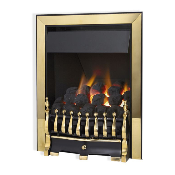
Arana RC
COAL EFFECT GAS FIRE
Installation and Maintenance Instructions
Hand these instructions to the user
Model No's GICC**RN is only for use on Natural Gas (G20) at a
supply pressure of 20 mbar in G.B. / I.E.
Model No's GICC**RP is only for use on Propane Gas (G31) at a
supply pressure of 37 mbar in G.B. / I.E.
** denotes trim / fret variant
Advertisement
Table of Contents

Related Manuals for Global Fires Arana RC


Summary of Contents for Global Fires Arana RC
- Page 1 Arana RC COAL EFFECT GAS FIRE Installation and Maintenance Instructions Hand these instructions to the user Model No’s GICC**RN is only for use on Natural Gas (G20) at a supply pressure of 20 mbar in G.B. / I.E. Model No’s GICC**RP is only for use on Propane Gas (G31) at a supply pressure of 37 mbar in G.B.
-
Page 2: Table Of Contents
CONTENTS Section 1 Information and Requirements PAGE Appliance Information Manual Handling Advice Conditions of Installation Flue and chimney suitability Fireplace / surround suitability Shelf position Chimney inspection Fire place opening / catchment space Fitting to Metal Flue Boxes Hearths 1.10 Spillage Monitoring System 1.11 Clearances to Combustible &... -
Page 3: Information And Requirements
SECTION 1 INFORMATION AND REQUIREMENTS APPLIANCE INFORMATION Model GICC**RN GICC**RP Gas Type Main injectors (2 off) Size 260 Size 85 Pilot Type Copreci Copreci 21100 / 162 21100 / 167 Max. Gross Heat Input : 6.9 kW 6.9 kW Min. Gross Heat Input : 4.2 kW 4.2 kW Cold Pressure :... -
Page 4: 1.1 Manual Handling Advice
1.1 MANUAL HANDLING ADVICE The following advice is offered when moving, manipulating and installing this product :- Always keep your back straight - bend using your legs Avoid twisting at your waist - reposition your feet instead Avoid upper body and top heavy bending - do not lean forwards or sideways Always grip the product with the palms of your hand - not the tips of your fingers... -
Page 5: Conditions Of Installation
INSTALLATION REQUIREMENTS CONDITIONS OF INSTALLATION In Great Britain :- It is the law that all gas appliances are installed only by a GAS SAFE Registered Installer in G.B. in accordance with these installation instructions and the Gas Safety (Installation and Use) Regulations (current edition). Failure to install appliances correctly could lead to prosecution. -
Page 6: Fireplace / Surround Suitability
Safe clearance of products must always be checked by carrying out a smoke match test as described. (see fig. 22 on page 26) FIREPLACE / SURROUND SUITABILITY The fire must only be installed on a hearth it must not be installed directly onto carpet or other combustible floor materials.The fire is suitable for fitting to non- combustible fire place surrounds and proprietary fire place surrounds with a temperature rating of at least 150 o c. -
Page 7: Chimney Inspection
FLUE / CHIMNEY INSPECTION Before commencing installation, a flue or chimney should be inspected to ensure that all the following conditions are satisfied. Check that the chimney / flue only serves one fire place and is clear of any obstruction. Any dampers or register plates must be removed or locked in the open position. -
Page 8: Fire Place Opening / Catchment Space
FIRE PLACE OPENING AND CHIMNEY CATCHMENT SPACE The front opening of the fire place must be between 400 and 450 mm wide, and between 550 and 570mm high. Any chairbrick that is in place must be removed before proceeding with the installation of this appliance. - Page 9 Table A - Installation Depth Requirements for a Global Arana being installed into a brick built chimney, requiring 12.0 litres of debris collection volume (fig. 2) Opening Width (mm) Minimum Depth Required (mm) 400 (minimum opening width) 450 (maximum opening width) For example, if the appliance was to be fitted into a 400mm wide opening, the depth required would be 298mm.
-
Page 10: Fitting To Metal Flue Boxes
1.8 FITTING TO PRE-FABRICATED TWIN WALL METAL FLUE BOXES The appliance may be fitted to twin wall metal flue boxes conforming to the con- structional requirements of BS 715, (for example the Selkirk LFE 175 box). The box must have a minimum flue diameter of 175mm internal and minimum internal dimensions of 300mm deep by 580mm high by 400mm wide. -
Page 11: Installation Of Fire
SECTION 2 INSTALLATION OF FIRE UNPACKING THE FIRE Carefully lift the fire out of the carton. Remove the loose item packaging carefully from the front of the appliance. Check the contents as listed :- Packing Check List 1off Fire box / burner assembly 1off Boxed ceramic base, front ceramic rail and 20 coals (18 large, 2 small) 1off... - Page 12 Proceed as follows :- Remove the trim / fret. Remove the burner heat shield from the front of the fire box to allow access to the burner. See fig. 5 below. Fig. 5 Ensure that the hearth is protected from damage and carefully lift the fire box into the fire opening, then slide it back into position.
- Page 13 Carefully remove the HT lead from the pilot assembly. Continue for all models Whilst the fire box is still in position, decide which side the gas supply is to enter the fire from. If concealed pipe work is required plan the pipe run to enter the fire box through one of the openings in the sides of the fire box below the fuelbed support panel and connect to the isolating / inlet elbow.
- Page 14 IMPORTANT : Sealing of the Gas Unused Gas Pipe Inlet Apertures In line with current GAS SAFE regulations, it is imperative that the gas supply inlet apertures that are not utilised during the installation are sealed with the foil tape as supplied. Failure to seal these inlet apertures could lead to flame reversal, which in turn will damage the burner and control systems of the product.
- Page 15 The preferred method of fixing which is suitable for almost all situations is the cable fixing method which is described in the following section in detail. If the 2 inch black spacer is used, the fire may be secured using the cable method as described below, or alternatively, in installations where the cable method is not suitable (eg.
- Page 16 Thread a tensioning screw over each of the cables and ensure that the tensioning nut is screwed fully up against the hexagon shoulder of the tensioning screw (this provides maximum travel for the tensioning nut). Fit a screwed nipple on to each of the cables and pull hand tight up against the tensioning screw, then secure each nipple with a flat bladed screwdriver.
- Page 17 The other firebox fixing method is as follows :- In installations where the cable method is not suitable (e.g. loose masonary in rear of fire opening) the firebox can be secured to the fire surround using four screws and wall plugs (not supplied). Below (fig.11) is a diagram to indicate the hole cen- tre positions available on the firebox to facilitate the screw fixing to the fireplace / surround.
-
Page 18: Gas Tightness And Inlet Pressure
GAS TIGHTNESS AND INLET PRESSURE Remove the pressure test point screw from the inlet elbow and fit a manometer. Turn on the main gas supply and carry out a gas tightness test. Depress both the round buttons on the handset. The fire will then commence its ignition sequence and will light to high. -
Page 19: Assembling Fuel Bed And Commissioning
SECTION 3 ASSEMBLING FUEL BED AND COMMISSIONING ASSEMBLING THE CERAMICS AND FUEL BED NOTE : The position of the fuel-bed components are critical to the performance of the product. Therefore please ensure that the fuel-bed components are positioned as described in the following section prior to requesting a service call due to soot build up, poor flame pattern etc. - Page 20 Fit five of the large sized coals onto the front ceramic rail, ensuring that they are evenly spaced. Use the recess’s in the front ceramic rail as a guide for placement. (See fig. 14 below) Fig. 14 Select four of the large coals and arrange behind the front row of coals, ensuring that flame paths as indicated below are not interupted.
- Page 21 Select five of the large coals and arrange along the rear of the fuelbed, using the ribs in the rear of the fuelbed as a guide for placement. (See fig. 16 below) Fig. 16 Select the four remaining large coals and position to fill the gaps at each end of the third row of coals, as shown.
- Page 22 The exact position and fit of the coals may be finely adjusted to give the most pleasing and random appearance. Warning : Use only the coals supplied with the fire. When replacing the coals remove the old coals and discard them. Fit a complete set of coals of the correct type.
-
Page 23: Connecting The Lithium Battery Pack
CONNECTING THE BATTERY PACK To prevent un-necessary battery drain, the battery pack that is used to provide the remote control function for this product is disconnected at the factory. Prior to attempting to light the product, can the installer please ensure that the battery pack is re-connected as shown in section b), c) &... -
Page 24: Fixing The Infrared Eye In Position
FIXING THE INFRARED SENSOR IN POSITION Due to the large amount of different fascia’s that can be supplied with these fires, the infrared sensor is supplied from the factory attached to a self adhesive pad. This pad can therefore be attached to the hearth in a position to suit the form of the fret or contemporary trim assembly that is chosen with the product. -
Page 25: Lighting The Appliance
LIGHTING THE APPLIANCE The Remote control handset generates an infrared signal, which will be received by the sensor situated at the front right of your fire, behind the ashpan cover. This infrared signal requires direct line of sight from the handset to the sensor on the fire to ensure good operation. -
Page 26: Checking For Clearance Of Combustion Products
Close all doors and windows in the room. Light the fire and allow to run for approximately 5 minutes on high position. After approximately 5 minutes hold a smoke match just inside and below the centre of the lower front edge of the top of the fire. See fig. 22 below (It is recommended that a suitable smoke match holder is used when checking for clearance of combustion products). -
Page 27: Maintenance
SECTION 4 MAINTENANCE Servicing Notes Servicing should be carried out annually by a competent person such as a GAS SAFE registered engineer. The service should include visually checking the chimney and fire opening for accumulations of debris and a smoke test to check for a positive up-draught in the chimney and must include an oxypilot change as a condition of the guarantee. - Page 28 Removing the Valve 4.2.1 Remove the burner assembly as in section 4.1 4.2.2 Remove the thermocouple retaing nut from the valve. remove the main pipe, inlet pipe and pilot pipe from the valve. 4.2.3 Remove the valve retaining screws and remove. Re-assemble in reverse order and carry out a gas tightness test.
- Page 29 PARTS SHORTLIST Replacement of parts must be carried out by a competent person such as a GAS SAFE registered gas installer. The part numbers of the replaceable parts are as follows, these are available from BFM Europe address shown below Gas Control Valve B-106790 Control Board...
Need help?
Do you have a question about the Arana RC and is the answer not in the manual?
Questions and answers