Advertisement
Quick Links
Advertisement

Related Manuals for EBN Technology TM50A-5B-VR


Summary of Contents for EBN Technology TM50A-5B-VR
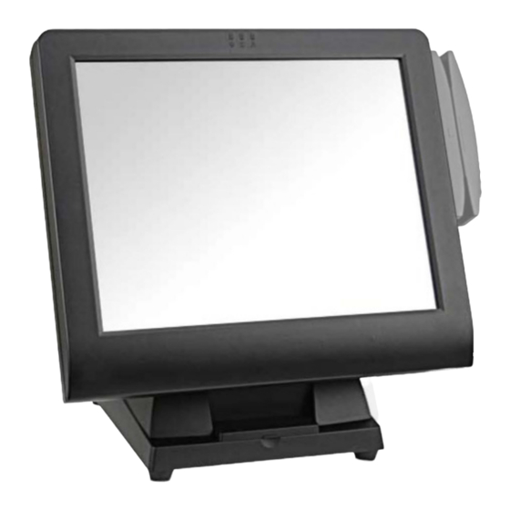
- Page 1 Service Manual TM50A-5B-VR/VU WTM50A-5B-VR/VU TM50A-2B-VR/VU WTM50A-2B-VR/VU...
- Page 2 Copyrights ©2012 All rights reserved. The information in this document is subject to change without prior notice in order to improve reliability, design and function and does not represent a commitment on the part of the manufacturer. This document contains proprietary information protected by copyright.
- Page 3 Contents Copyrights ....................i Liability Disclaimer ...................i Contents....................ii 1. Before You Start ...................1 2. Base Unit Separating ................2 3. The Main Unit..................4 Contents...
- Page 4 Before You Start 1. Please unplug the power cable before you start to work. 2. Please read and follow the instructions in this document carefully. Failure to follow these instructions could damage your device and void the warranty. 1.1. Tools Suggested All procedures in this document require the following tools: #0 Phillips screwdriver #1 Phillips screwdriver...
- Page 5 Base Unit Separating 1. Adjust the main unit to the position as shown below. 2. Loosen and remove the four screws fixing the base unit by #1 Phillips screwdriver. 3. Remove the right hinge cover, left hinge cover and support cover as shown below. Chapter 2...
- Page 6 4. Remove the five screws. 5. Remove the base unit. Chapter 2...
- Page 7 The Main Unit Following steps are for TM50A-5B-VR/VU and WTM50A-5B-VR/VU: 1. Loosen and remove the eight screws in blue circles as shown below by #1 Phillips screwdriver and then remove the rear panel from the LCD assembly. 2. Loosen and remove the four screws in blue circles as shown below by #1 Phillips screwdriver.
- Page 8 4. Unplug: 1. LCD panel cable, 2. speaker cable, 3. LED indicator, 4. inverter cable, 5. MSR cable and 6. touch cable. 5. Loosen and remove the five screws and then remove the LCD control board. 6. Remove the LED indicator. 7.
- Page 9 8. Unplug the three connectors from the LCD inverter. 9. Loosen the three screws and remove the LCD inverter. 10. Loosen the two screws and remove the LED lens. 11. Loosen the ten screws, and then take out the LCD assembly. Chapter 3...
- Page 10 12. Loosen the three screws to remove the touch panel. 13. Loosen the four screws to remove the LCD panel from the LCD chassis. 14. On the back side of the LCD panel, remove the black tape and unplug the LCD cable. 15.
- Page 11 Following steps are for TM50A-2B-VR/VU and WTM50A-2B-VR/VU 1. Loosen and remove the eight screws in blue circles as shown below by #1 Phillips screwdriver and then remove the rear panel from the LCD assembly. 2. Loosen and remove the four screws in blue circles as shown below by #1 Phillips screwdriver.
- Page 12 4. Unplug: 1. LCD panel cable, 2. speaker cable, 3. LED indicator and 4. touch cable. 5. Loosen and remove the five screws and then remove the LCD control board. 6. Remove the black tape. 7. Remove the LED indicator. Chapter 3...
- Page 13 8. Loosen the four screws to remove the speaker. 9. Unplug the two connectors from the LCD inverter. 10. Loosen the three screws and remove the LCD inverter. 11. Loosen the two screws and remove the LED lens. Chapter 3...
- Page 14 12. Loosen the eight screws, and then take out the LCD assembly. 13. Loosen the two screws to remove the touch panel. 14. Loosen the four screws to remove the LCD panel from the LCD chassis. 15. On the back side of the LCD panel, remove the black tape and unplug the LCD cable.
Need help?
Do you have a question about the TM50A-5B-VR and is the answer not in the manual?
Questions and answers