
Related Manuals for Keeler vantage+


Summary of Contents for Keeler vantage+
-
Page 1: Service Manual
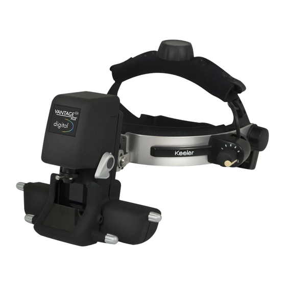
Indirect Ophthalmoscope Service Manual ALWAYS READ THE INSTRUCTIONS Keeler Limited, Clewer Hill Road, Windsor, Berks, United Kingdom. SL4 4AA. Tel No. +44 (0) 1 753 857177Fax No. +44 (0) 1 753 830247 2415-P-7011 Issue A 07/07/2008... -
Page 2: Table Of Contents
Vantage + Service Manual 2415-P-7011 CONTENTS Introduction Service Principles Tools Required Precautions Disassembly Remove the Optics Head from the Browbar Remove the Front Cover Remove the Optics Head and Illumination Assy. Reassembly Refit Illumination Assy and Viewing Assy Refit to Browbar Spare Parts List Issue A 07/07/2008... -
Page 3: Introduction
Vantage + Service Manual 2415-P-7011 Introduction This manual covers servicing of both the Bulb and LED illuminated versions. The only difference lies in the Illumination Assy and the Dimmer PCB Assy which are not interchangeable. Damage may occur if an attempt is made to mix the Bulb and LED Illumination Assy and Dimmer PCBs. -
Page 4: Tools Required
Vantage + Service Manual 2415-P-7011 Tools Required Most of the tools required will be in standard electro-mechanical toolkit. The following special tools will make assembly and disassembly easier. TD351 Lock Ring Key for Eyepieces. Page 2 Issue A 07/07/2008... -
Page 5: Precautions
Vantage + Service Manual 2415-P-7011 Precautions Care should be taken to carry out any repair work on a clean soft surface to minimise damage to the outside of the unit. Solvents should not be used for cleaning. Page 3 Issue A 07/07/2008... -
Page 6: Disassembly
Vantage + Service Manual 2415-P-7011 Disassembly Virtually all repairs inside the head unit except changing the Centre Mirror involve removing both the Viewing Optics Assy and the Illumination Assy from the Rear Cover. This involves removing the whole Optics Assy from the Browbar. -
Page 7: Remove The Front Cover
Vantage + Service Manual 2415-P-7011 Remove the Front Cover 1. Remove 2 off Mirror Spindle Knob (25) by gently pulling. 2. Carefully lift 2 off Control Knob Label (21) with the point of a sharp blade. They are self adhesive. 3. -
Page 8: Remove The Optics Head And Illumination Assy
Vantage + Service Manual 2415-P-7011 Remove the Optics Head and Illumination Assy. 1. Unscrew 2 off Eye Cap (3) being careful not to lose the +2D Eye Lenses (2). 2. Unscrew 2 off Eyepiece Lock Ring using TD351 Lock Ring Key. 3. - Page 9 Vantage + Service Manual 2415-P-7011 5. The Viewing Assy (27) and Illumination Assy (28) are joined by the Centre Spindle (24) and must be removed together. 6. Remove 2 off M2 x 8 Csk PT Screws (13) from the Viewing Assy (27). 7.
-
Page 10: Reassembly
Vantage + Service Manual 2415-P-7011 Reassembly Refit Illumination Assy and Viewing Assy Great care must be taken to avoid any strain on the Eyepiece Mirror Mounts as these have been carefully aligned on the laser jig during manufacture. Avoid holding the Viewing Assy by the Mirror Mounts. Refer to Figure 4 1. - Page 11 Vantage + Service Manual 2415-P-7011 4. Lay the Viewing and Illumination Assemblies together as shown below ensuring that the Centre Spindle remains engaged at both ends. 5. Carefully thread the cable from the Illumination Assy up through the Rear Cover Moulding ensuring that the cable is not twisted. 6.
-
Page 12: Refit To Browbar
Vantage + Service Manual 2415-P-7011 17. Carefully fit the Light Shield (12) over the 2 pins in the Viewing Assy ensuring that it fits under the Mirror. 18. Carefully blow out any dust in the unit. 19. Offer the Front Cover Assy over the main assembly ensuring that the Light Shield (12) fits into the slots behind the window. - Page 13 Vantage + Service Manual 2415-P-7011 Refer to figure 1 3. The cable must be a total of 135mm long including the stripped ends from the Grommet in the Browbar. If a new cable has been fitted 3.1 Trim the cable to 135mm from the grommet. 3.2 Separate the 2 wires for 15mm from the free end 3.3 Strip the covering from the wires for 3mm and tin.
-
Page 14: Spare Parts
Parts marked with are only available as part of a spares kit (1202-P-7299). Current prices for spare parts are available from Technical Service. Technical Service Keeler Ltd Clewer Hill Road Windsor Berks SL4 4AA... -
Page 15: Spare Parts List
Vantage + Service Manual 2415-P-7011 Spare Parts List The following parts are common to both versions Item Part No Description EP79-11000 Browbar Grommet EP39-53721 +2D Eye Lens EP39-53641 Eye Piece Cap EP39-70189 Light Shield EP39-70197 Control Knob EP79-09795 Knob Body EP39-70178 Dimmer Control Body EP39-70174... - Page 16 Vantage + Service Manual 2415-P-7011 The following parts are specific to the Bulb version. Item Part No Description 1202-P-7280 Front Cover Moulding (Bulb) 1202-P-5795 Illumination Optics (Bulb) 1012-P-5241 Vantage Plus Bulb 1202-P-6253 Dimmer PCB Assy (Bulb) The following parts are specific to the LED version. Item Part No Description...
- Page 17 Vantage + Service Manual 2415-P-7011 Page 15 Issue A 07/07/2008...
- Page 18 Vantage + Service Manual 2415-P-7011 Page 16 Issue A 07/07/2008...
- Page 19 Vantage + Service Manual 2415-P-7011 Page 17 Issue A 07/07/2008...
- Page 20 Vantage + Service Manual 2415-P-7011 Page 18 Issue A 07/07/2008...
Need help?
Do you have a question about the vantage+ and is the answer not in the manual?
Questions and answers