Toro Power Clear 721 QZE Operator's Manual
Hide thumbs
Also See for Power Clear 721 QZE:
- Operator's manual (20 pages) ,
- Operator's manual (20 pages) ,
- Operator's manual (24 pages)
Table of Contents
Advertisement
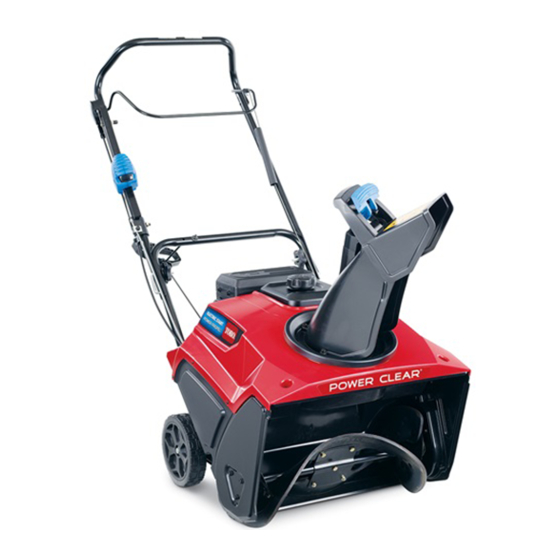
Power Clear
Model No. 38744—Serial No. 400010798 and Up
Introduction
WARNING
CALIFORNIA
Proposition 65 Warning
This product contains a chemical or chemicals
known to the State of California to cause cancer,
birth defects, or reproductive harm.
The engine exhaust from this product
contains chemicals known to the State of
California to cause cancer, birth defects,
or other reproductive harm.
This machine is intended to be used by residential
homeowners or professional, hired operators. It is
designed primarily for removing snow from paved
surfaces, such as driveways and sidewalks, and other
surfaces for traffic on residential or commercial
properties. It is not designed for removing materials
other than snow, nor is it designed for clearing off gravel
surfaces.
Read this information carefully to learn how to operate and
maintain your machine properly and to avoid injury and
machine damage. You are responsible for operating the
machine properly and safely.
You may contact Toro directly at www.Toro.com for machine
and accessory information, help finding a dealer, or to register
your machine.
Whenever you need service, genuine Toro parts, or additional
information, contact an Authorized Service Dealer or Toro
Customer Service and have the model and serial numbers of
your machine ready.
Figure 1
model and serial numbers on the machine. Write the numbers
in the space provided.
© 2016—The Toro® Company
8111 Lyndale Avenue South
Bloomington, MN 55420
®
721 QZE Snowthrower
identifies the location of the
Register at www.Toro.com.
1. Model and serial number location
Model No.
Serial No.
This manual identifies potential hazards and has safety
messages identified by the safety-alert symbol
which signals a hazard that may cause serious injury or death
if you do not follow the recommended precautions.
1. Safety-alert symbol
This manual uses 2 words to highlight information.
Important calls attention to special mechanical information
and Note emphasizes general information worthy of special
attention.
Important: If you are using this machine above 1500 m
(5,000 ft) for a continuous period, ensure that the High
Altitude Kit has been installed so that the engine meets
CARB/EPA emission regulations. The High Altitude
Kit increases engine performance while preventing
spark-plug fouling, hard starting, and increased
emissions. Once you have installed the kit, attach
the high-altitude label next to the serial decal on the
machine. Contact any Authorized Toro Service Dealer
to obtain the proper High Altitude Kit and high-altitude
label for your machine. To locate a dealer convenient to
Original Instructions (EN)
All Rights Reserved *3406-730* A
Printed in the USA
Form No. 3406-730 Rev A
Operator's Manual
Figure 1
(Figure
Figure 2
2),
Advertisement
Table of Contents

Related Manuals for Toro Power Clear 721 QZE


Summary of Contents for Toro Power Clear 721 QZE
-
Page 1: Introduction
You are responsible for operating the machine properly and safely. You may contact Toro directly at www.Toro.com for machine and accessory information, help finding a dealer, or to register Figure 2 your machine. -
Page 2: Table Of Contents
Changing the Engine Oil .........14 Toro Customer Care Department at the number(s) listed Servicing the Spark Plug ..........15 in your Emission Control Warranty Statement. Replacing the Drive Belt ..........16 Adjusting the Quick Shoot™ Control......17 Remove the kit from the engine and restore the engine Storage ................19... -
Page 3: Figure
Safety • Keep clear of any discharge opening. Keep bystanders a safe distance away from the machine. • • Keep children out of the operating area. Never allow Read and understand the contents of this Operator’s Manual children to operate the machine. before you start the engine. -
Page 4: Setup
Setup Loose Parts Use the chart below to verify that all parts have been shipped. Procedure Description Qty. – No parts required Unfold the handle. Screw Chute assembly Install the discharge chute. Discharge-chute handle Unfolding the Handle No Parts Required Procedure Figure 5 1. -
Page 5: Filling The Engine With Oil
Max fill:. 0.60 L (20 oz), type: automotive detergent oil with an API service classification of SJ, SL, or higher. Figure 8 below to select the best oil viscosity for the outdoor temperature range expected. Installing the Discharge Chute Parts needed for this procedure: Screw Chute assembly Discharge-chute handle... -
Page 6: Adjusting The Control Cable
Product Overview Adjusting the Control Cable No Parts Required Procedure Refer to Adjusting the Control Cable (page 13). Figure 10 1. Chute-deflector trigger 8. Electric-start button 2. Discharge chute 9. Ignition key 3. Fuel-tank cap 10. Choke lever 4. Control bar 11. -
Page 7: Operation
Operation Before Operation Safety • Use extension cords and receptacles as specified by the manufacturer for all machines with electric-starting motors. • Do not operate the machine without wearing adequate winter garments. Avoid loose fitting clothing that can get caught in moving parts. Wear slip resistant footwear that will improve footing on slippery surfaces. -
Page 8: During Operation
Note: You may tip the machine forward (handle up) • Do not overload the machine capacity by attempting to to make adding oil easier. Remember to return the clear snow at too fast a rate. machine to the operating position before checking the •... - Page 9 WARNING Number of primes Temperature 0°F (-18°C) or above The electrical cord can become damaged, causing a shock or fire. Below 0°F (-18°C) Thoroughly inspect the electrical cord before plugging it into a power source. If the cord is damaged, do not use it to start the machine.
-
Page 10: Engaging The Rotor Blades
Engaging the Rotor Blades To engage the rotor blades, hold the control bar against the handle (Figure 19). Figure 21 Adjusting the Discharge Chute and Chute Deflector Figure 19 1. Control bar To adjust the discharge chute, press the trigger of the Quick Shoot™... -
Page 11: Clearing A Clogged Discharge Chute
After Operation Safety • Never store the machine with fuel in the fuel tank inside a building where ignition sources are present, such as hot water heaters, space heaters, or clothes dryers. Allow the engine to cool before storing in any enclosure. Figure 23 •... -
Page 12: Maintenance
• Do not change the governor settings on the engine. • Purchase only genuine Toro replacement parts and Note: Ensure that a 2 mm to 3 mm (1/16 inch to 1/8 inch) accessories. gap exists between the control bar and the handle (Figure 25). -
Page 13: Inspecting The Rotor Blades
Adjusting the Control Cable 1. Slide up the spring cover and unhook the spring from the adjuster link (Figure 26). Figure 27 1. Remove the upper end of 3. Pivot point spring from this hole. 2. Insert the upper end of 4. -
Page 14: Changing The Engine Oil
Changing the Engine Oil Max fill: 0.60 L (20 oz), type: automotive detergent oil with an API service classification of SJ, SL, or higher. Service Interval: After the first 2 hours Figure 31 below to select the best oil viscosity for Yearly the outdoor temperature range expected. -
Page 15: Servicing The Spark Plug
Servicing the Spark Plug Service Interval: Yearly—Check the spark plug and replace it if necessary. Use a NGK BPR6ES or Champion RN9YC spark plug or equivalent. 1. Shut off the engine and wait for all moving parts to stop. 2. Rotate the discharge chute so that it faces forward. 3. -
Page 16: Replacing The Drive Belt
13. Connect the wire to the spark plug. Note: Ensure that the breather tube is routed above the spark-plug wire as shown in Figure Figure 37 1. Drive-belt cover 6. Drive belt 2. Bolt (3) 7. Rotor shaft Figure 36 3. -
Page 17: Adjusting The Quick Shoot™ Control
8. Install the brake spring onto the idler arm (Figure 38). 9. Install the drive belt cover with the bolts that you removed in step 1. Note: Ensure that the drive belt is properly adjusted and operating; refer to Checking the Control Cable (page 12) Adjusting the Control Cable (page 13). - Page 18 4. Hold the discharge chute in the straight-ahead position, pull the lower cable casing downward until you remove the slack in the cable, and tighten the screw on the lower cable clamp securely (Figure 43). Figure 43 1. Lower cable casing 5.
-
Page 19: Storage
Storage 16. Cover the machine and store it in a clean, dry place out of the reach of children. Allow the engine to cool before storing it in any enclosure. Storing the Snowthrower WARNING • Gasoline fumes are highly flammable, explosive, and dangerous if inhaled. - Page 20 Notes:...
- Page 21 Notes:...
- Page 22 Such use will not reduce the warranty obligations of The Toro Company. 10. Add-on or modified parts that are not approved by The Toro Company may not be used. The use of a non-approved add-on or modified parts by the purchaser will be grounds for disallowing a warranty claim.
- Page 23 Warranted Parts The following emission warranty parts are covered, to the extent these parts were present on the Toro engine/equipment and/or Toro supplied fuel system: 1. Fuel System Parts • Carburetor and internal parts • Cold starting enrichment (primer or choke) •...
- Page 24 Toro importer. If all other remedies fail, you may contact us at Toro Warranty Company. Australian Consumer Law: Australian customers will find details relating to the Australian Consumer Law either inside the box or at your local Toro Dealer.
Need help?
Do you have a question about the Power Clear 721 QZE and is the answer not in the manual?
Questions and answers
What size socket is required to remove sparkplug?
What are the dimensions of the oil filler cap?