Table of Contents
Advertisement
Quick Links
Advertisement
Table of Contents
Troubleshooting

Related Manuals for DFI MB336-NRM


Summary of Contents for DFI MB336-NRM
- Page 1 MB336-NRM MicroATX Industrial Motherboard User’s Manual K33600431...
-
Page 2: Copyright
Copyright FCC and DOC Statement on Class B This publication contains information that is protected by copyright. No part of it may be re- This equipment has been tested and found to comply with the limits for a Class B digital produced in any form or by any means or used to make any transformation/adaptation without device, pursuant to Part 15 of the FCC rules. -
Page 3: Table Of Contents
Table of Contents COM (Serial) Ports ..................22 Cooling Fan Connectors................23 Power Connectors ..................23 Chassis Intrusion Connector ................ 24 Front Panel Connector ................24 Copyright ......................2 Standby Power LED ..................25 S/PDIF Connector ..................25 Trademarks Expansion Slots ..................26 ...................... -
Page 4: About This Manual
About this Manual Static Electricity Precautions An electronic file of this manual is included in the CD. To view the user’s manual in the CD, It is quite easy to inadvertently damage your PC, system board, components or devices even insert the CD into a CD-ROM drive. -
Page 5: About The Package
About the Package The package contains the following items. If any of these items are missing or damaged, please contact your dealer or sales representative for assistance. • One MB336 motherboard • One Serial ATA data cable • One I/O shield •... -
Page 6: Chapter 1 - Introduction
Chapter 1 Chapter 1 - Introduction Rear Panel I/O • 1 mini-DIN-6 port for PS/2 mouse/keyboard Specifications • 4 USB 3.0/2.0/1.1 ports Ports • 8 USB 2.0/1.1 ports • 3 DisplayPorts Processor • LGA 1155 socket for: • 2 RJ45 LAN ports ®... -
Page 7: Features
Chapter 1 • Wake-On-LAN Features This feature allows the network to remotely wake up a Soft Power Down (Soft-Off) PC. It • Watchdog Timer is supported via the onboard LAN port or via a PCI LAN card that uses the PCI PME (Power Management Event) signal. -
Page 8: Power Failure Recovery
Chapter 1 • Wake-On-PS/2 This function allows you to use the PS/2 keyboard or PS/2 mouse to power-on the system. Important: The 5V_standby power source of your power supply must support ≥720mA. • Power Failure Recovery When power returns after an AC power failure, you may choose to either power-on the system manually or let the system power-on automatically. -
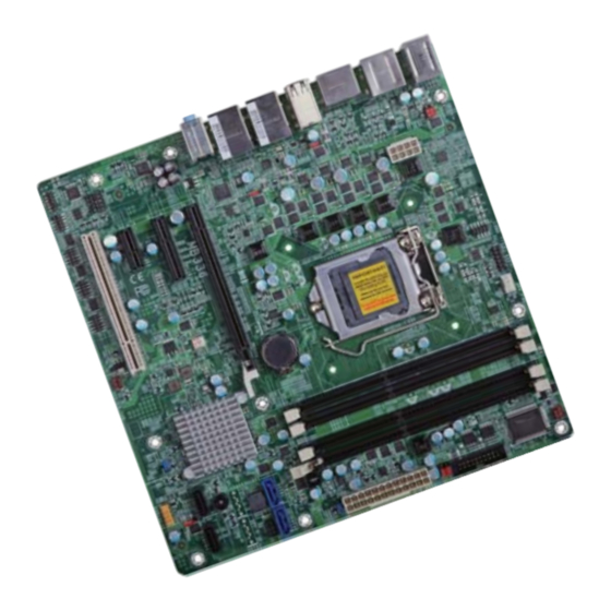
Page 9: Chapter 2 - Hardware Installation
Chapter 2 Chapter 2 - Hardware Installation Important: Board Layout Electrostatic discharge (ESD) can damage your board, processor, disk drives, add-in boards, and other components. Perform installation procedures at an ESD workstation only. If such a station is not available, you can provide some ESD protection by wear- ing an antistatic wrist strap and attaching it to a metal part of the system chassis. -
Page 10: Installing The Dimm Module
Chapter 2 Installing the DIMM Module The system board supports the following memory interface. Note: Single Channel (SC) The system board used in the following illustrations may not resemble the actual Data will be accessed in chunks of 64 bits (8B) from the memory channels. board. -
Page 11: Cpu
Chapter 2 6. Grasping the module by its edges, position the module above the socket with the “notch” in the module aligned with the “key” on the socket. The keying mechanism ensures the module can be plugged into the socket in only one way. The system board is equipped with a surface mount LGA 1155 socket. -
Page 12: Installing The Cpu
Chapter 2 Load lever Installing the CPU 5. Lifting the load lever will at the same time lift the load plate. 1. Make sure the PC and all other peripheral devices connected to it has been powered down. Lift the load lever up to 2. - Page 13 Chapter 2 7. Insert the CPU into the 8. Close the load plate then socket. The gold triangular push the load lever down. mark on the CPU must align with the corner of While closing the load the CPU socket shown on plate, make sure the front Retention knob edge of the load plate...
-
Page 14: Installing The Fan And Heat Sink
Chapter 2 Installing the Fan and Heat Sink 4. Rotate each push-pin ac- cording to the direction of the arrow shown on top of The CPU must be kept cool by using a CPU fan with heat sink. Without sufficient air circula- the pin. -
Page 15: Jumper Settings
Chapter 2 Jumper Settings PS/2 Keyboard/Mouse Power Select Clear CMOS Data 1-2 On: +5V (default) 2-3 On: +5V_standby 1-2 On: Normal (default) 2-3 On: Clear CMOS Data If you encounter the followings, JP1 is used to select the power of the PS/2 keyboard/mouse port. Selecting +5V_standby will allow you to use the PS/2 keyboard or the PS/2 mouse to wake up the system. -
Page 16: Usb Power Select
Chapter 2 USB Power Select Power-on Select 1-2 On: +5V 2-3 On: (default) +5V_standby USB 8-9/10-11 (JP4) 1-2 On: Power-on via power button (default) JP10 USB 4-7 (JP11) 2-3 On: Power-on via AC power USB 0-1/2-3 (JP5) 1-2 On: +5V (default) USB 12-13 (JP8) -
Page 17: Digital I/O Output State
Chapter 2 Digital I/O Output State DIO 3/5/7/9 (JP14) DIO 11/13/15/17 (JP13) 1-2 On: +5V (default) 2-3 On: GND JP13 (DIO pin 11/13/15/17) and JP14 (DIO pin 3/5/7/9) are used to select the state of DIO output: pull high or pull low. Chapter 2 Hardware Installation... -
Page 18: Rear Panel I/O Ports
Chapter 2 Rear Panel I/O Ports PS/2 Keyboard/Mouse Port PS/2 Keyboard/Mouse USB 2.0 LAN 1 LAN 2 Display USB 2.0 Line-in/Surround Port PS/2 KB/MS Line-out USB 2.0 Mic-in/ Center+Subwoofer Display Display USB 3.0 USB 3.0 Port Port The rear panel I/O ports consist of the following: •... -
Page 19: Graphics Interfaces
Chapter 2 Graphics Interfaces RJ45 LAN Ports The display ports consist of the following: • 3 DisplayPorts LAN 1 LAN 2 LAN 1 DP 3 LAN 2 DP 2 DP 1 Features • Intel WG82579LM with iAMT8.0 Gigabit Ethernet Phy ®... -
Page 20: Usb Ports
Chapter 2 USB Ports Wake-On-USB Keyboard/Mouse The Wake-On-USB Keyboard/Mouse function allows you to use a USB keyboard or USB mouse to wake up a system from the S3 (STR - Suspend To RAM) state. To use this function: USB 9 •... -
Page 21: Audio
Chapter 2 Audio I/O Connectors SATA (Serial ATA) Connectors Rear Audio Line-in/Surround Line-out Mic-in/ Center+Subwoofer SATA 3.0 6Gb/s SATA 1 SATA 0 SATA 2.0 3Gb/s Front Audio SATA 5 SATA 4 Rear Audio The system board is equipped with 3 audio jacks. A jack is a one-hole connecting interface for inserting a plug. -
Page 22: Digital I/O Connector
Chapter 2 Digital I/O Connector COM (Serial) Ports DCD- DTR- COM 5: RS232 DSR- RTS- CTS- Digital I/O COM 5 The 8-bit Digital I/O connector provides powering-on function to external devices that are connected to these connectors. The pin functions of the 8-bit digital I/O connector are listed below. -
Page 23: Cooling Fan Connectors
Chapter 2 Cooling Fan Connectors Power Connectors +12V CPU Fan Power +12V Ground 12 24 Speed Control Ground +3.3VDC Power ATX power +5VDC +12VDC System Fan 2 Sense +5VDC +12VDC +5VSB +5VDC PWR_OK +5VDC PS_ON# +5VDC -12VDC +3.3VDC +3.3VDC +3.3VDC System Fan 1 Use a power supply that complies with the ATX12V Power Supply Design Guide Version 1.1. -
Page 24: Chassis Intrusion Connector
Chapter 2 Chassis Intrusion Connector Front Panel Connector Chassis Intrusion ATX-SW PWR-LED Front Signal Panel Ground RESET-SW HDD-LED HDD-LED - HDD LED The board supports the chassis intrusion detection function. Connect the chassis intrusion This LED will light when the hard drive is being accessed. sensor cable from the chassis to this connector. -
Page 25: Standby Power Led
Chapter 2 Standby Power LED S/PDIF Connector Standby Power LED SPDIF out Ground SPDIF in S/PDIF The S/PDIF connector is used to connect an external S/PDIF port. Your S/PDIF port may be This LED will lit red when the system is in the standby mode. It indicates that there is power mounted on a card-edge bracket. -
Page 26: Expansion Slots
Chapter 2 Expansion Slots LPC Debug Connector PCI Express x16 PCI Express x4 PCI Express x1 PCI Express x16 Slot Install PCI Express x16 graphics card, that comply to the PCI Express specifications, into the PCI Express x16 slot. To install a graphics card into the x16 slot, align the graphics card above the slot then press it down firmly until it is completely seated in the slot. -
Page 27: Battery
Chapter 2 Battery Battery The lithium ion battery powers the real-time clock and CMOS memory. It is an auxiliary source of power when the main power is shut off. Safety Measures • Danger of explosion if battery incorrectly replaced. • Replace only with the same or equivalent type recommend by the manufacturer. •... -
Page 28: Chapter 3 - Bios Setup
Chapter 3 Chapter 3 - BIOS Setup Legends Overview Keys Function The BIOS is a program that takes care of the basic level of communication between the CPU and peripherals. It contains codes for various advanced features found in this system board. Right and Left arrows Moves the highlight left or right to select a menu. -
Page 29: Ami Bios Setup Utility
Chapter 3 AMI BIOS Setup Utility Advanced The Advanced menu allows you to configure your system for basic operation. Some entries are Main defaults required by the system board, while others, if enabled, will improve the performance of your system or let you set some features according to your preference. The Main menu is the first screen that you will see when you enter the BIOS Setup Utility. - Page 30 Chapter 3 ACPI Power Management Configuration Wake System with Fixed Time This section is used to configure the ACPI Power Management. Enable or disable the system to wake on the alarm event. When Enabled, the system will wake on the hr::min::sec. specified. Aptio Setup Utility - Copyright (C) 2011 American Megatrends, Inc.
- Page 31 Chapter 3 PC Health Status Boundary 1-4 This section displays SIO Hardware Health Monitor. Enter the boundary value. The range is 0 to 127. Speed Count 1-5 Aptio Setup Utility - Copyright (C) 2011 American Megatrends, Inc. Advanced Enter the speed coount value. The range is 1 to 100. System Hardware Monitor Smart Fan Function System Smart Fan Control...
- Page 32 Chapter 3 Trusted Computing CPU Configuration This section configures settings relevant to Trusted Computing innovations. This section is used to configure the CPU setting. Aptio Setup Utility - Copyright (C) 2011 American Megatrends, Inc. Aptio Setup Utility - Copyright (C) 2011 American Megatrends, Inc. Advanced Advanced CPU Confi...
- Page 33 Chapter 3 SATA Configuration Port 0/1/4/5 This section is used to configure the functions of Serial ATA devices. This field is used to enable or disable the Serial ATA port. Aptio Setup Utility - Copyright (C) 2011 American Megatrends, Inc. Hot Plug Advanced Designates the Serial ATA port as Hot pluggable.
- Page 34 Chapter 3 Software Feature Mask Configuration IRRT Only on eSATA RAID OROM/RST driver will refer to the SWFM configuration to enable or disable the Enabled storage features. When enabled, only IRRT volumes on eSATA can span internal and eSATA drives. Disabled Aptio Setup Utility - Copyright (C) 2011 American Megatrends, Inc.
- Page 35 Chapter 3 Intel TXT(LT) Configuration AMT Configuration This section is used to configure the function of the Intel Trusted Execution Technology. This section is used to configure the parameters of the Active Management Technology. Aptio Setup Utility - Copyright (C) 2011 American Megatrends, Inc. Aptio Setup Utility - Copyright (C) 2011 American Megatrends, Inc.
- Page 36 Chapter 3 USB Configuration F71879 Super IO Configuration This section is used to configure the parameters of the USB device. This section is used to configure the I/O functions supported by the onboard Super I/O chip. Aptio Setup Utility - Copyright (C) 2011 American Megatrends, Inc. Aptio Setup Utility - Copyright (C) 2011 American Megatrends, Inc.
- Page 37 Chapter 3 Serial Port 5 Configuration F71879 Second Super IO Configuration Set parameters of the serial port 5 (COM E). This section is used to configure the I/O functions supported by the onboard Super I/O chip. Aptio Setup Utility - Copyright (C) 2011 American Megatrends, Inc. Aptio Setup Utility - Copyright (C) 2011 American Megatrends, Inc.
- Page 38 Chapter 3 Aptio Setup Utility - Copyright (C) 2011 American Megatrends, Inc. Aptio Setup Utility - Copyright (C) 2011 American Megatrends, Inc. Advanced Advanced Enable or Disable Serial Serial Port 2 Confi guration Enable or Disable Serial Serial Port 4 Confi guration Port (COM) Port (COM) [Enabled]...
-
Page 39: Chipset
Chapter 3 Chipset South Bridge This section is used to configure the parameters of South Bridge. This section configures relevant chipset functions. Aptio Setup Utility - Copyright (C) 2011 American Megatrends, Inc. Aptio Setup Utility - Copyright (C) 2011 American Megatrends, Inc. Chipset Main Advanced... - Page 40 Chapter 3 PCI Express Configuration PCI Express Root Port This field configures PCI Express root port settings. This option is used to control the PCI Express root port. (If the PCI root port is disabled, then all the PCI Express root port is always disabled.) ASPM Support Aptio Setup Utility - Copyright (C) 2011 American Megatrends, Inc.
- Page 41 Chapter 3 SECE USB Configuration This option is used to enable or disable the System Error on Correctable Error for the This field configures USB settings. PCI Express root port. PME SCI Aptio Setup Utility - Copyright (C) 2011 American Megatrends, Inc. Chipset This option is used to enable or disable the PME SCI for the PCI Express root port.
- Page 42 Chapter 3 North Bridge PCH Azalia Configuration This section is used to configure the parameters of North Bridge. This field configures PCH Azalia settings. Aptio Setup Utility - Copyright (C) 2011 American Megatrends, Inc. Aptio Setup Utility - Copyright (C) 2011 American Megatrends, Inc. Chipset Chipset PCH Azalia Confi...
- Page 43 Chapter 3 Graphics Configuration Primary IGFX Boot Display This field configures the graphics settings. Select the video device which will be activated during POST. This has no effect if the external graphics presents. Secondary boot display selection will appear based on your selection.
- Page 44 Chapter 3 NB PCIe Configuration Memory Configuration This field is used to configure the settings of NB PCI Express. This field only displays the memory configuration. Aptio Setup Utility - Copyright (C) 2011 American Megatrends, Inc. Aptio Setup Utility - Copyright (C) 2011 American Megatrends, Inc. Chipset Chipset NB PCIe Confi...
-
Page 45: Boot
Chapter 3 Boot ME Subsystem This section only displays the parameters of the Management Engine Technology. Aptio Setup Utility - Copyright (C) 2011 American Megatrends, Inc. Main Advanced Chipset Boot Security Save & Exit Aptio Setup Utility - Copyright (C) 2011 American Megatrends, Inc. Boot Confi... - Page 46 Chapter 3 CSM Parameters Skip VGA When Enabled, BIOS will skip the EFI VGA driver. Aptio Setup Utility - Copyright (C) 2011 American Megatrends, Inc. Main Advanced Chipset Boot Security Save & Exit Skip USB This option controls if Launch CSM [Enabled] CSM will be launched.
-
Page 47: Security
Chapter 3 Security Save & Exit Aptio Setup Utility - Copyright (C) 2011 American Megatrends, Inc. Aptio Setup Utility - Copyright (C) 2011 American Megatrends, Inc. Main Advanced Chipset Boot Security Save & Exit Main Advanced Chipset Boot Security Save & Exit Save Changes and Reset Reset the system after Password Description... -
Page 48: Updating The Bios
Chapter 3 Updating the BIOS Restore User Defaults To restore user default to all the setup options, select this field and then press <En- To update the BIOS, you will need the new BIOS file and a flash utility, AFUDOS. ter>. -
Page 49: Chapter 4 - Supported Software
Chapter 4 Chapter 4 - Supported Software For Windows 7 The CD that came with the system board contains drivers, utilities and software applications required to enhance the performance of the system board. Insert the CD into a CD-ROM drive. The autorun screen (Mainboard Utility CD) will appear. If after inserting the CD, “Autorun”... -
Page 50: Intel Chipset Software Installation Utility
Chapter 4 For Windows XP Intel Chipset Software Installation Utility The Intel Chipset Software Installation Utility is used for updating Windows INF files so that ® the Intel chipset can be recognized and configured properly in the system. To install the utility, click “Intel Chipset Software Installation Utility” on the main menu. 1. - Page 51 Chapter 4 Microsoft DirectX 9.0C (For Windows XP) 3. Go through the readme document for more installa- tion tips then click Next. To install the utility, click “Microsoft DirectX 9.0C Driver” on the main menu. 1. Click “I accept the agreement”...
- Page 52 Chapter 4 Microsoft .NET Framework 3.5 (For Windows XP) 3. Click Exit. Note: Before installing Microsoft .NET Framework 3.5, make sure you have updated your Windows XP operating system to Service Pack 3. To install the driver, click “Microsoft .NET Framework 3.5” on the main menu. 1.
- Page 53 Chapter 4 Intel Graphics Drivers (For Windows 7 and Windows 8) 3. Go through the readme document for system re- quirements and installation To install the driver, click “Intel Graphics Drivers” on the main menu. tips then click Next. 1. Setup is now ready to install the graphics driver.
- Page 54 Chapter 4 Intel Graphics Drivers (For Windows XP) 4. Setup is currently installing the driver. After installation has completed, click Next. To install the driver, click “Intel Graphics Drivers” on the main menu. 1. Setup is ready to install the graphics driver.
-
Page 55: Audio Drivers
Chapter 4 Audio Drivers Intel LAN Drivers To install the driver, click “Audio Drivers” on the main menu. To install the driver, click “Intel LAN Drivers” on the main menu. 1. Setup is ready to install the 1. Setup is ready to install the driver. -
Page 56: Intel Management Engine Drivers
Chapter 4 Intel Management Engine Drivers 4. Click Install to begin the installation. To install the driver, click “Intel Management Engine Drivers” on the main menu. 1. Setup is ready to install the driver. Click Next. 5. After completing installa- tion, click Finish. -
Page 57: Dfi Utility
3. Setup is currently installing the driver. After installation has completed, click Next. DFI Utility provides information about the board, Watchdog,and DIO. To access the utility, click “DFI Utility” on the main menu. Note: If you are using Windows 7, you need to access the operating system as an administrator to be able to install the utility. - Page 58 Chapter 4 3. Click “Install” to begin the The DFI Utility icon will appear on the desktop. Double-click the icon to open the utility. installation. 4. After completing installa tion, click “Finish”. Information HW Health Chapter 4 Supported Software...
- Page 59 Chapter 4 HW Health Set WatchDog Chapter 4 Supported Software...
- Page 60 Chapter 4 Intel USB 3.0 Drivers (For Windows 7) 3. Go through the readme docu- ment for more installation tips then click Next. To install the driver, click “Intel USB 3.0 Driver” on the main menu. 1. Setup is ready to install the driver. Click Next.
-
Page 61: Intel Rapid Storage Technology
Chapter 4 F6 Floppy Intel Rapid Storage Technology This is used to create a floppy driver diskette needed when you install Windows XP using the The Intel Rapid Storage Technology is a utility that allows you to monitor the current status ®... - Page 62 Chapter 4 3. Read the license agreement then 6. Click “Yes, I want to restart my click Yes. computer now” then click Finish. Restarting the system will allow the new software installation to take effect. 4. Go through the readme document for system requirements and instal- lation tips then click Next.
- Page 63 Chapter 4 Infineon TPM Driver and Tool 4. Enter the necessary information and then click Next. To install the driver, click “Infineon TPM driver and tool” on the main menu. 1. The setup program is preparing to install the driver. 5.
- Page 64 Chapter 4 7. TPM requires installing the Micro- 10. Click “Yes“ to restart your system. soft Visual C++ package prior to installing the utility. Click Install. 8. The setup program is currently installing the Microsoft Visual C++ package. 9. Click Finish. Chapter 4 Supported Software...
- Page 65 Chapter 4 Adobe Acrobat Reader 9.3 To install the reader, click “Adobe Acrobat Reader 9.3” on the main menu. 1. Click Next to install or click Change Destination Folder to select another folder. 2. Click Install to begin installa- tion. 3.
-
Page 66: Chapter 5 - Raid
Chapter 5 Chapter 5 - RAID Settings The system board allows configuring RAID on Serial ATA drives. It supports RAID 0, RAID 1, To enable the RAID function, the following settings are required. RAID 5 and RAID 10. 1. Connect the Serial ATA drives. RAID Levels 2. - Page 67 Chapter 5 Step 4: Install the RAID Driver During OS Installation Step 5: Install the Intel Rapid Storage Technology Utility The RAID driver must be installed during the Windows XP or Windows 2000 installation us- The Intel Rapid Storage Technology Utility can be installed from within Windows. It allows ®...
- Page 68 Chapter 5 5. Read the license agree- ment then click Yes. 6. Go through the readme document to view system requirements and installa- tion information then click Next. 7. Click “Yes, I want to restart my computer now” then click Finish. Chapter 5 RAID...
-
Page 69: Chapter 6 - Intel Amt Settings
Chapter 6 Chapter 6 - Intel AMT Settings Enable Intel AMT in the AMI BIOS ® Overview 1. Power-on the system then press <Del> to enter the main menu of the AMI BIOS. Intel Active Management Technology (Intel AMT) combines hardware and software solution to ®... -
Page 70: Extension (Mebx) Screen
Chapter 6 Enable Intel AMT in the Intel Management 4. In the Save & Exit menu, select Save Changes and Reset then select OK. ® ® Engine BIOS Extension (MEBX) Screen Aptio Setup Utility - Copyright (C) 2011 American Megatrends, Inc. Main Advanced Chipset... - Page 71 Chapter 6 3. Enter a new password in the space provided under Intel(R) ME New Password then press 4. You will be asked to verify the password. Enter the same new password in the space pro- Enter. The password must include: vided under Verify Password then press Enter.
- Page 72 Chapter 6 6. Select Change Intel(R) ME Password then press Enter. Select Local FW Update then press Enter. Select Enabled then press Enter. You will be prompted for a password. The default password is “admin”. Enter the default password in the space provided under Intel(R) ME New Password then press Enter. Intel(R) Management Engine BIOS Extension v8.0.0.0061/Intel(R) ME v8.0.4.1441 Copyright(C) 2003-12 Intel Corporation.
- Page 73 Chapter 6 In the Intel(R) ME Power Control menu, select Intel(R) ME ON in Host Sleep Select Previous Menu until you return to the Main Menu. Select Intel(R) AMT Con- States then press Enter. Select an option then press Enter. figuration then press Enter.
- Page 74 Chapter 6 In the Intel(R) AMT Configuration menu, select SOL/IDER/KVM then press Enter. In the SOL/IDER/KVM menu, select SOL then press Enter. Select Disabled then press Enter. Intel(R) Management Engine BIOS Extension v8.0.0.0061/Intel(R) ME v8.0.4.1441 Intel(R) Management Engine BIOS Extension v8.0.0.0061/Intel(R) ME v8.0.4.1441 Copyright(C) 2003-12 Intel Corporation.
- Page 75 Chapter 6 In the SOL/IDER/KVM menu, select KVM then press Enter. Select Disabled then Select Enabled then press Enter. press Enter. Intel(R) Management Engine BIOS Extension v8.0.0.0061/Intel(R) ME v8.0.4.1441 Intel(R) Management Engine BIOS Extension v8.0.0.0061/Intel(R) ME v8.0.4.1441 Copyright(C) 2003-12 Intel Corporation. All Rights Reserved. Copyright(C) 2003-12 Intel Corporation.
- Page 76 Chapter 6 In the User Consent menu, select User Opt-in then press Enter. Select None then Select Previous Menu until you return to the Intel(R) AMT Configuration menu. Select press Enter. Password Policy then press Enter. You may choose to use a password only during setup and configuration or to use a pass- word anytime the system is being accessed.
- Page 77 Chapter 6 In the Intel(R) ME Network Setup menu, select Intel(R) ME Network Name Set- Select Domain Name then press Enter. Enter the computer’s domain name then press tings then press Enter. Enter. Intel(R) Management Engine BIOS Extension v8.0.0.0061/Intel(R) ME v8.0.4.1441 Intel(R) Management Engine BIOS Extension v8.0.0.0061/Intel(R) ME v8.0.4.1441 Copyright(C) 2003-12 Intel Corporation.
- Page 78 Chapter 6 Select Dynamic DNS Update then press Enter. Select Enabled or Disabled then press In the TCP/IP Settings menu, select Wired LAN IPV4 Configuration then press Enter. Enter. Intel(R) Management Engine BIOS Extension v8.0.0.0061/Intel(R) ME v8.0.4.1441 Intel(R) Management Engine BIOS Extension v8.0.0.0061/Intel(R) ME v8.0.4.1441 Copyright(C) 2003-12 Intel Corporation.
- Page 79 Chapter 6 In the Intel(R) AMT Configuration menu, select Unconfigure Network Access then In the Intel(R) Remote Setup And Configuration menu, select Current Provision- press Enter. ing Mode then press Enter. Intel(R) Management Engine BIOS Extension v8.0.0.0061/Intel(R) ME v8.0.4.1441 Intel(R) Management Engine BIOS Extension v8.0.0.0061/Intel(R) ME v8.0.4.1441 Copyright(C) 2003-12 Intel Corporation.
- Page 80 Chapter 6 Select Previous Menu until you return to the Intel(R) Remote Setup And Configu- In the Intel(R) Remote Automated Setup And Configuration menu, select RCFG ration menu. Select Provisioning Server IPV4/IPV6 then press Enter. Type server then press Enter. Select Start Configuration, and type Y then press Enter. address then press Enter.
- Page 81 Chapter 6 In the Intel(R) TLS PSK Configuration menu, select Set PID and PPS ** then Select Previous Menu until you return to the Intel(R) Remote Setup And Configura- press Enter. Type PID code then press Enter. tion menu. Select TLS PKI then press Enter. Intel(R) Management Engine BIOS Extension v8.0.0.0061/Intel(R) ME v8.0.4.1441 Intel(R) Management Engine BIOS Extension v8.0.0.0061/Intel(R) ME v8.0.4.1441 Copyright(C) 2003-12 Intel Corporation.
- Page 82 Chapter 6 In the Intel(R) Remote Configuration menu, select PKI DNS Suffix then press Select Previous Menu until you return to the Main Menu. Select Exit then press Enter. Enter. Type PKI DNS Suffix then press Enter. Type Y then press Enter. Intel(R) Management Engine BIOS Extension v8.0.0.0061/Intel(R) ME v8.0.4.1441 Intel(R) Management Engine BIOS Extension v8.0.0.0061/Intel(R) ME v8.0.4.1441 Copyright(C) 2003-12 Intel Corporation.
-
Page 83: Appendix A - Troubleshooting
Appendix A Appendix A - NLITE and AHCI Installation Guide 4. Insert the XP installation disc into an optical drive. nLite 5. Launch nLite. The Welcome screen will appear. Click nLite is an application program that allows you to customize your XP installation disc by Next. - Page 84 Appendix A 7. Click Next. 9. Click Insert and then select Multiple driver folder to select the drivers you will integrate. Click Next. Select only the drivers ap- 8. In the Task Selection dialog propriate for the Windows box, click Drivers and version that you are using Bootable ISO.
- Page 85 Appendix A If you are uncertain of The program is currently the southbridge chip used integrating the drivers on your motherboard, and applying changes to select all RAID/AHCI the installation. controllers and then click When the program is finished applying the changes, click Next.
- Page 86 Appendix A To create an image, You have finished cus- select the Create Image tomizing the Windows mode under the General XP installation disc. Click section and then click Finish. Next. Enter the BIOS utility to configure the SATA con- troller to RAID/AHCI.
-
Page 87: Ahci
Appendix A AHCI 5. In the Hardware Update Wizard dialog box, select “No, not this time” then The installation steps below will guide you in configuring your SATA drive to AHCI mode. click Next. 1. Enter the BIOS utility and configure the SATA controller to IDE mode. 2. - Page 88 Appendix A A warning message 8. Click “Have Disk”. appeared because the se- lected SATA controller did not match your hardware device. Ignore the warning and click Yes to proceed. Click Finish. 9. Select C:\AHCI\iaAHCI.inf and then click Open. The system’s settings have been changed.
-
Page 89: Appendix B - Watchdog Sample Code
Appendix B Appendix B - Watchdog Sample Code ;Software programming example: ;--------------------------------------------- ;(1) Enter Super IO Confi guration mode ;--------------------------------------------- DX,4EH AL,87H DX,AL DX,AL ;------------------------------------------------------------------------------------------- ;(2) Confi guration Logical Device 8, register CRF0/CRF1 (WDT Control/WDT timer) ;------------------------------------------------------------------------------------------- DX,4EH AL,07H ;Ready to Program Logical Device DX,AL DX,4FH AL,08H... -
Page 90: Appendix C - System Error Message
Appendix C Appendix C - System Error Message Hard Disk(s) fail (20) When the BIOS encounters an error that requires the user to correct something, either a beep HDD initialization error. code will sound or a message will be displayed in a box in the middle of the screen and the message, PRESS F1 TO CONTINUE, CTRL-ALT-ESC or DEL TO ENTER SETUP, will be shown in Hard Disk(s) fail (10) the information box at the bottom. -
Page 91: Appendix D - Troubleshooting
Appendix D Appendix D - Troubleshooting Checklist The picture seems to be constantly moving. Troubleshooting Checklist 1. The monitor has lost its vertical sync. Adjust the monitor’s vertical sync. 2. Move away any objects, such as another monitor or fan, that may be creating a magnetic This chapter of the manual is designed to help you with problems that you may encounter field around the display. -
Page 92: Hard Drive
Appendix D Hard Drive System Board 1. Make sure the add-in card is seated securely in the expansion slot. If the add-in card is Hard disk failure. loose, power off the system, re-install the card and power up the system. 1.
Need help?
Do you have a question about the MB336-NRM and is the answer not in the manual?
Questions and answers