
Subscribe to Our Youtube Channel
Related Manuals for DFI M8M051


Summary of Contents for DFI M8M051
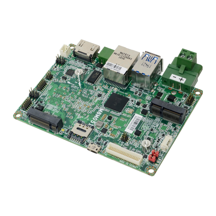
- Page 1 M8M051 2.5" Pico-ITX Motherboard User’s Manual © December 26, 2022 DFI Inc. A-609-M-2040...
- Page 2 1. The changes or modifications not expressly approved by the party responsible for compliance could void the user’s authority to operate the equipment. 2. Shielded interface cables must be used in order to comply with the emission limits. User's Manual | M8M051...
-
Page 3: Table Of Contents
Flash image into SD card ....................24 Android OS - Flash Images into eMMC/SD card using UUU tool ........25 Software Features ........................26 General Support List ......................26 Linux AP/API Support List ....................26 Yocto Support List ......................26 Android Support List .....................28 User's Manual | M8M051... - Page 4 To avoid damage to the system, use the correct AC input voltage range. • To reduce the risk of electric shock, unplug the power cord before removing the system chassis cover for installation or servicing. After installation or servicing, cover the system chassis before plugging the power cord. User's Manual | M8M051...
- Page 5 The board and accessories in the package may not come similar to the information listed above. This may differ in accordance with the sales region or models in which it was sold. For more information about the standard package in your region, please contact your dealer or sales representative. User's Manual | M8M051...
-
Page 6: Chapter 1 - Introduction
Support eMMC 5.1 16GB on board (default) Support up to 64GB (opt.) 1 x Micro SD Slot 1 x 8-bit DIO (2 x 6 header, 1.27mm pitch) I²C 1 x I²C (1.27mm pitch) CANBus 1 x CANBus 2.0 User's Manual | M8M051... -
Page 7: Features
However, if your system is in the Suspend mode, you can power-on the system only through an IRQ or DMA interrupt. Wake-On-USB This function allows you to use a USB keyboard or USB mouse to wake up a system from the S3 (STR - Suspend To RAM) state. User's Manual | M8M051... -
Page 8: Chapter 2 - Hardware Installation
If a wrist strap is unavailable, establish and maintain contact with the system chassis throughout any procedures requiring ESD protection. User's Manual | M8M051... -
Page 9: Installing The Heat Sink
4 mounting holes around the board. 3. Screw tight two of the spring screws at opposite corners into the mounting holes. And then proceed with the other two spring screws. Mounting holes User's Manual | M8M051... -
Page 10: Jumper Settings
The JP4 is used to determine the Audio „ 1-2 Off: Internal Boot „ 5-6 Off: EMMC@eSDHC „ 1: Mic Input „ 2/3/5: GND (default) (default) „ 1-2 On: Serial Downloader „ 5-6 On: uSD@eSDHC2 „ 4: R-CH „ 6: L-CH User's Manual | M8M051... -
Page 11: Led Backlight (Jp5)
The JP5 is used to select the voltage level and power level of LED Blacklight: +5V or +3.3V for voltage and +12V or +5V for power. Control Signal Voltage Backlight Power „ 1-3 On: 5V „ 5-6 On: 12V „ 1-2 On: 3.3V „ 4-6 On: 5V User's Manual | M8M051... -
Page 12: External I/O Ports
Use a power adapter with 12V DC output voltage. Using a voltage higher than the recommended one may fail to boot the system or cause damage to the system board. Important: DC Jack is available upon request. User's Manual | M8M051... -
Page 13: Usb 3.1 Gen 1 & Micro Usb 2.0
USB allows data exchange between your computer and a wide range of simultaneously accessible external Plug and Play peripherals. The system board is equipped with multiple USB Type - two USB 3.1 ports and 1 micro USB 2.0. User's Manual | M8M051... -
Page 14: Com 3 (Rs485)
The COM 3 port provides 2-wire RS485 communication with support for auto flow control. The HDMI port which carries both digital audio and video signals is used to connect a LCD monitor or digital TV. Assignment DATA-_RS485 DATA+_RS485 User's Manual | M8M051... -
Page 15: Internal I/O Connectors
The Wake-On-USB Keyboard/Mouse function allows you to use a USB keyboard or a USB mouse to wake up the system from the S state(s). Assignment „ J3 USB 2.0 Headers (3/4) VDD_3V3 DEBUG_UART1_RXD Assignment Assignment DEBUG_UART1_TXD +5VUSBHDR +5VUSBHDR USBH_DN_HDR1 USBH_DN_HDR2 USBH_DP_HDR1 USBH_DP_HDR2 User's Manual | M8M051... -
Page 16: J8 I²C
The Digital I/O connector supports 8-bit digital input/output signals to provide powering-on function of the connected devices. „ J8 I²C „ J5 DIO Function Function Function Function PWM_OUT VDD_3v3/+VTP_3V3 +5V_DIO TP_SCL TP_ALT# DIO0_C DIO1_C TP_SDA TP_RST# DIO2_C DIO3_C DIO4_C DIO5_C DIO6_C DIO7_C User's Manual | M8M051... -
Page 17: J11 Lvds
LCD/Inverter power connector. These connectors transmit video signals and +VDD_Panel_3V3 +VDD_Panel_5V power from the system board to the LCD Display Panel. Refer to the next page for the pin functions of these connectors. User's Manual | M8M051... -
Page 18: J9 Com2 / Com4
This switch allows you to reboot without having to power off the system. SOUTN2 CTSN2 Power_LED This LED indicates power status. DCDN4 SINN4 RTSN4 SOUTN4 „ J7 Front Panel CTSN4 DTRN4 Function Function ONOFF_BTN# FP_LED_3.3V FP_PWM_3.3V SYS_nRST FP_RSV_BTN# User's Manual | M8M051... -
Page 19: J1 Battery
The adhesive tape on the battery is used for flexible positioning. Its lifetime may be shrunk if exposed to high temperature. „ CN12 CANbus Connect to the Function battery connector +VDD_CAN CAN1H CAN1L „ J1 Battery Function Function +VBAT User's Manual | M8M051... -
Page 20: Expansion Slots
The SIM slot on the system board is used to insert a SIM card and can be used in conjunction with the Mini PCI Express slot to provide mobile communication capability. I2C Connector The I2C connector is used to monitor or communicate with system components. „ I2C Connector Assignment 3.3V TP_SCL TP_ALT# TP_SDA TP_RST# User's Manual | M8M051... -
Page 21: Chapter 3 - Software User Guide
BOOT Type as Serial Download mode by plugging one jumper into JP1 shorting pin1 and pin2. 3. See the pictures shown as below. 4. Connect M8M051 with PC via UART-USB debug board and USB cable for showing debug log at the terminal •... - Page 22 Sometimes, UUU flashing process might FAIL, because Windows are runtime installing necessary • Open the Command Prompt in Windows, or open the Terminal in Ubuntu after necessary prepara- drivers. User can see the following processes be executed when flashing images into M8M051 tions are done device.
-
Page 23: Windows Winusb Driver Install For Windows Uuu Tool
7.2 Install updated winusb inf file (Mandatory to flash image in Windows) - Unzip winusb.zip to \mfgtools-uuu_M8M051\ - Run install.bat with administrator permission - Reboot Windows after drivers installed, windows will install necessary USB download gadget driver. User's Manual | M8M051... -
Page 24: Flash Image Into Sd Card
Connect JP1 as below picture and power on device to force it to enter SD card boot mode. 8.2 SD boot mode configuration change Connect JP1 as below picture and power on device to force it to enter SD card download mode. User's Manual | M8M051 ver.011_A_1-1221_19-20... -
Page 25: Android Os - Flash Images Into Emmc/Sd Card Using Uuu Tool
>uuu_imx_android_flash_hdmi.bat -f imx8mq -a –e ( for HDMI panel image) >uuu_imx_android_flash_lvds.bat -f imx8mq -a –e ( for LVDS panel image) 3. • Connect M8M051 with PC via UART-USB debug board and USB cable for showing debug log at the terminal •... -
Page 26: Software Features
4. Support audio recording console command for test recording WAV file with Mono brightness control platform. MIC_IN audio, file store to eMMC. Support “lspci” console command for check PCIe card status. Support “lsusb” console command for check PCIe card status. 2242/3042 B key 4GLTE module: Quectel EM06 User's Manual | M8M051... - Page 27 3. rootfs.tar.bz2: compressed: Around 481 MB UART3 - Free storage Around 11.7 GB free space (eMMC size 16GB, around 2.3GB used of 14GB file system Support Loopback test, BR 115200 (need DFI Linux user space utility). RS485 size size, /dev/root)
-
Page 28: Android Support List
Version For M.2 Kernel Version 4.14.98 UART2 - Support DTE mode, BR 115200 with CTS/RTS follow control loopback test (need DFI RS232 Android test utility). eMMC Support eMMC boot , eMMC v5.1, Linux ext4 file system UART3 - Support Loopback test, BR 115200 (need DFI Android test utility). - Page 29 Android No support suspend, set never to suspend by default. Suspend UART4 - Support Loopback test, BR 115200 (need DFI Android test utility). RS485 1. AOSP WebView Browser Tester: Browser APP. 2. AOSP Calculator: Calculator APP. 3. AOSP Calendar: Calendar APP.
Need help?
Do you have a question about the M8M051 and is the answer not in the manual?
Questions and answers