Table of Contents
Advertisement
Quick Links
Advertisement
Table of Contents

Related Manuals for DFI M8MP553


Summary of Contents for DFI M8MP553
- Page 1 M8MP553 3.5" SBC Motherboard User’s Manual Preliminary...
- Page 2 1. The changes or modifications not expressly approved by the party responsible for compliance could void the user’s authority to operate the equipment. 2. Shielded interface cables must be used in order to comply with the emission limits. User's Manual | M8MP553...
-
Page 3: Table Of Contents
DPJ1 LCD Panel ......................24 CMJ1 Camera ........................25 J1 JTAG ..........................26 BTJ1 Battery ........................26 Expansion Slots ........................27 Installing the M.2 Module .....................27 Chapter 3 - Software User Guide ....................28 Flash Images using UUU tool - V1.1 ...................28 User's Manual | M8MP553... - Page 4 To avoid damage to the system, use the correct AC input voltage range. • To reduce the risk of electric shock, unplug the power cord before removing the system chassis cover for installation or servicing. After installation or servicing, cover the system chassis before plugging the power cord. User's Manual | M8MP553...
- Page 5 The board and accessories in the package may not come similar to the information listed above. This may differ in accordance with the sales region or models in which it was sold. For more information about the standard package in your region, please contact your dealer or sales representative. User's Manual | M8MP553...
-
Page 6: Chapter 1 - Introduction
2 x CAN bus 2.0b on Industrial CPU sku Storage eMMC 1 x eMMC 5.1 with default 16GB (up to 64GB) Watchdog Timer Output & Interval System Reset, Programmable via Software from 1 to 255 Seconds User's Manual | M8MP553... - Page 7 Operating: 5 to 90% RH Storage: 5 to 90% RH MTBF Mechanism Dimensions 3.5" SBC Form Factor 146mm (5.75") x 102mm (4.02") Height PCB: TBD Top Side: TBD Bottom Side: TBD Standards and Certi- Certifications CE, FCC, RoHS fications User's Manual | M8MP553...
-
Page 8: Features
However, if your system is in the Suspend mode, you can power-on the system only through an IRQ or DMA interrupt. Wake-On-USB This function allows you to use a USB keyboard or USB mouse to wake up a system from the S3 (STR - Suspend To RAM) state. User's Manual | M8MP553... -
Page 9: Chapter 2 - Hardware Installation
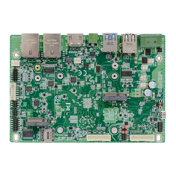
ESD protection. JTAG SPI (3.3V) Boot-CFG Audio For USB 2.0 Download Mode Front Panel USB2_3/4 LED Backlight LCD LVDS COM1/COM4 I2C/ Touch (3.3V) eMMC uSD Card LCD Backlight(5V/12V) I2C/Touch(3.3V) Debug(COM2) CAN1 CAN2 User's Manual | M8MP553... -
Page 10: Installing The Heat Sink
3. Screw tight two of the spring screws at opposite corners into the mounting holes. And then proceed with the other two spring screws. Mounting holes eMMC uSD Card LCD Backlight(5V/12V) I2C/Touch(3.3V) Debug(COM2) CAN1 CAN2 User's Manual | M8MP553... -
Page 11: Jumper Settings
„ 5-6 Off: EMMC@ „ 1-3 On: „ 5-6 On: (default) eSDHC3 (default) Backlight Power 12V (default) „ 1-2 On: Serial Downloader „ 5-6 On: uSD@eSDHC2 „ 4-6 On: „ 1-2 On: Backlight Power 5V 3.3V User's Manual | M8MP553... -
Page 12: External I/O Ports
The external I/O ports consist of the following: • 1 DC-in 2-poles Terminal Block • 2 USB 3.1 • 2 USB 2.0 • 2 LAN • 1 COM 3 Important: • 1 HDMI DC Jack is available upon request. • Micro USB • User's Manual | M8MP553... -
Page 13: Usb 2.0/3.1 & Micro Usb
LAN (RJ-45) The onboard RJ45 LAN port allows the system board to connect to network by ethernet. USB allows data exchange between your computer and a wide range of simultaneously accessible external Plug and Play peripherals. User's Manual | M8MP553... -
Page 14: Com 3 (Rs485)
The COM 3 port provides 2-wire RS485 communication with support for auto flow control. The HDMI port which carries both digital audio and video signals is used to connect a LCD monitor or digital TV. Assignment Assignment DATA-_RS485 DATA+_RS485 User's Manual | M8MP553... -
Page 15: Usd Slot
Chapter 2 HARDWARE INSTALLATION External I/O Ports uSD Slot eMMC uSD Card LCD Backlight(5V/12V) I2C/Touch(3.3V) Debug(COM2) CAN1 CAN2 uSD Card Slot This slot is for a MicroSD card. User's Manual | M8MP553... -
Page 16: Internal I/O Connectors
The Wake-On-USB Keyboard/Mouse function allows you to use a USB keyboard or a USB mouse to wake up the system from the S state(s). Assignment +3.3V UART2_RX Assignment Assignment UART2_TX +5VUSBHDR +5VUSBHDR USBH_DN_HDR1 USBH_DN_HDR2 USBH_DP_HDR1 USBH_DP_HDR2 User's Manual | M8MP553... -
Page 17: Audio (Aujp1)
The AUJP1 is used to connect to the audio device. „ 1: „ 2: GND +3.3V_TP „ 1: „ 2/3/5: GND MIC_IN „ 3: TP_SCL „ 4: TP_ALT# „ 4: R-CH „ 6: L-CH „ 5: TP_SDA „ 4: TP_RST# User's Manual | M8MP553... -
Page 18: Dio (Iojp1, 5V)
The Digital I/O connector supports 8-bit digital input/output signals to provide powering-on function of the connected devices. „ 1: GND „ 2: PWM „ 9: DIO4 „ 10: DIO5 „ 3: GND „ 4: +5V_DIO „ 11: DIO6 „ 12: DIO7 User's Manual | M8MP553... -
Page 19: Front Panel (Fpjp1, 3.3V)
This switch allows you to reboot without having to power off the system. Power_LED This LED indicates power status. „ 2: FP_LED „ 3: GND „ 1: ONOFF_BTN# „ 6: RSV_BTN# „ 4: FP_PWM „ 5: RST# User's Manual | M8MP553... -
Page 20: Com1 / Com4 (Tsjp1)
LCD LVDS COM1/COM4 I2C/ Touch (3.3V) „ 7: DCDN4 „ 8: SINN4 „ 1: SINN1 „ 2: RTSN1 „ 9: RTSN4 „ 10: SOUTN4 „ 3: SOUTN1 „ 4: CTSN1 „ 11: CTSN4 „ 12: DTRN4 User's Manual | M8MP553... -
Page 21: Tpj1 I²C / Touch(3.3V)
The I2C connector is used to monitor or communicate with system components. The CAN bus (Controller Area Network) connector is used for interconnecting electronic control units (ECUs). „ CAN1 „ CAN2 Function Function Function CAN1H CAN2H TP_RST# CAN1L CAN2L TP_ALT# +VTP_3V3 TP_SCL TP_SDA User's Manual | M8MP553... -
Page 22: Blj1 Lcd Backlight (5V/12V)
Card LCD Backlight(5V/12V) I2C/Touch(3.3V) Debug(COM2) CAN1 CAN2 The BLJ1 connector is to determine the signal output of the LCD panel. Function VLED_12V / 5V VLED_12V / 5V VLED_12V / 5V Backlight On / Off Backlight Dimming User's Manual | M8MP553... -
Page 23: Sfj1 Fan
USB2_3/4 LED Backlight LED Backlight LCD LVDS LCD LVDS COM1/COM4 COM1/COM4 I2C/ I2C/ Touch (3.3V) Touch (3.3V) The fan connector connects to the system fan. The SIM slot is for SIM card installation. Function PWM_FAN TACH_FAN User's Manual | M8MP553... -
Page 24: Dpj1 Lcd Panel
LCD Display Panel. LVDS_A1- LVDS_B0+ Refer to the next page for the pin functions of these connectors. LVDS_A1+ LVDS_B0- LVDS_A_CLK- LVDS_B_CLK- LVDS_A_CLK+ LVDS_B_CLK+ +VDD_3.3V +VDD_3.3V +VDD_3.3V +VDD_3.3V +VDD_3.3V +VDD_3.3V User's Manual | M8MP553... -
Page 25: Cmj1 Camera
CSI1_DN0 CSI2_DN0 Audio For USB 2.0 CSI1_DP0 CSI2_DP0 Download Mode Front Panel USB2_3/4 LED Backlight CSI1_DN1 CSI2_DN1 LCD LVDS COM1/COM4 I2C/ Touch (3.3V) CSI1_DP1 CSI2_DP1 CM1_GPIO CM2_GPIO CM1_RST# CM2_RST# I2C4_SCL I2C3_SCL I2C4_SDA I2C3_SDA +3.3V +3.3V +3.3V User's Manual | M8MP553... -
Page 26: J1 Jtag
Safety Measures • There exists explosion hazard if the battery is incorrectly installed. • Replace only with the same or equivalent type recommended by the manufacturer. • Dispose of used batteries according to local ordinances. User's Manual | M8MP553... -
Page 27: Expansion Slots
Screw tight the card onto the stand-off with a screw driver and a stand-off screw until the gap between the card and the stand-off closes up. The card should be lying parallel to the board when it’s correctly mounted. User's Manual | M8MP553... -
Page 28: Chapter 3 - Software User Guide
For eMMC to update bootloader and kernel image only Linux kernel Image DeviceTree blob bootloader RootFS file Linux update script Linux update tool Windows update tool Please ensure that usb cable is connected to the microUSB slot. Execute "upate_all.bat" with administrator privileges. User's Manual | M8MP553... - Page 29 During the flashing process, the red light and blue light are active. If the text in green "Done" appears, the process is finished. After the process is done, please switch JP1 back to 1-2/5-6 OFF to boot from eMMC. User's Manual | M8MP553...
- Page 30 Switch JP1 Boot jumper to 1-2 ON for Download mode. Enter the "Linux" directory and type "./update_all.sh" in terminal. Then the update process will begin with information in the terminal that indicates progress. If the text in green "Done" appears, the process is finished. User's Manual | M8MP553...
Need help?
Do you have a question about the M8MP553 and is the answer not in the manual?
Questions and answers