Bosch DICENTIS Hardware Installation Manual
Hide thumbs
Also See for DICENTIS:
- Installation manual ,
- Configuration manual (134 pages) ,
- Software manual (99 pages)
Table of Contents
Advertisement
Advertisement
Table of Contents

Related Manuals for Bosch DICENTIS


Summary of Contents for Bosch DICENTIS
- Page 1 DICENTIS Conference System Hardware Installation Manual...
-
Page 3: Table Of Contents
Mechanical installation of Central Equipment Audio Powering Switch and Powering Switch Mechanical installation of Contribution Devices DICENTIS devices DICENTIS Microphones DCNM-MMDSP Anti-reflection foil DCNM-NCH Name Card Holder Installation Test Bosch Security Systems B.V. Hardware Installation Manual 2016.09 | V1.4 |... -
Page 4: Safety
These instructions are supplied together with all equipment that can be connected to the mains supply. Safety precautions Some of the DICENTIS Conference System products are designed to be connected to the public mains network. To avoid any risk of electric shock, all interventions must be carried out with disconnected mains supply. -
Page 5: About This Manual
DICENTIS About this manual | en About this manual The purpose of this manual is to provide information required for installing the DICENTIS Conference System. This installation manual is available as a digital document in the Adobe portable document format (PDF). -
Page 6: Document History
Terminology updated. 2016.07 V1.4 edition. Terminology updated. DCN multimedia changed to DICENTIS. Sections updated: 3.1, 3.2, 4.1, 4.3.1, 4.3.2, 4.4.1, 4.4.2, 4.4.3, 5.3, 5.4, 7.1, 7.2, 7.3, 7.4, 8. 2016.09 | V1.4 | Hardware Installation Manual Bosch Security Systems B.V. -
Page 7: System Installation Overview
It is advisable to participate in the DICENTIS Conference System training before you install, configure, prepare, and operate a DICENTIS Conference System. The DICENTIS Conference System is an IP based conference system which runs on an OMNEO compatible Ethernet network. It is used for distributing and processing audio, video and data signals. -
Page 8: Typical System Setup
Participants can use their DICENTIS device to contribute to a meeting. – 5.1 is a DICENTIS multimedia Device used for “system power on/off”. This device is always connected to the powered socket of the Audio Powering Switch or Powering Switch. - Page 9 DICENTIS System installation overview | en This system overview does not give information on redundant network options. For more information, refer to Redundancy options, page 21. Bosch Security Systems B.V. Hardware Installation Manual 2016.09 | V1.4 |...
-
Page 10: System Extension
| System installation overview DICENTIS System extension The DICENTIS Conference System is scalable from small to medium to large. This section describes what a small, medium and large system is and what the requirements are for these systems: A small DICENTIS Conference System (see Typical system setup, page 8) consists of: –... - Page 11 ARNI must be used. – OMN-ARNIS (ARNI‑S OMNEO interface): The ARNI‑S is required for increasing the system size above 100 DICENTIS devices. It supports up to 450 DICENTIS nodes in its subnet. It also acts as a DHCP server in its subnet. –...
- Page 12 – The timer can be reached when: – you use cable redundancy. – the system is incorrectly wired. 2016.09 | V1.4 | Hardware Installation Manual Bosch Security Systems B.V.
- Page 13 DICENTIS System installation overview | en Multi subnet DICENTIS Conference System The following figure illustrates a typical multi subnet DICENTIS Conference System with a total of 1200 DICENTIS devices. – The system is divided over four (4) subnets, where two (2) subnets having a maximum of 400 DICENTIS devices and an OMN-ARNIS are connected.
-
Page 14: System Installation Design And Planning
Notice! Make sure that the cable lengths and power consumptions do not exceed the specifications. Not doing so will result in malfunctioning at any moment of the DICENTIS Conference System and products. System capabilities The capability of the DICENTIS Conference System and DICENTIS products depends on: –... - Page 15 The calculation tool can be used to calculate the total power capacity of the system. This makes the design and planning of the DICENTIS Conference System easier. The calculation tool uses the power consumption of the devices and the system network cable lengths to calculate the needed system power supply capacity.
-
Page 16: Hardware Requirements
Non-blocking backplane per switching port, i.e. 2 Gbit per port (e.g. 16 Gbps for an 8‑port router). – MAC address table of at least 1000 addresses per directly connected subnet. 2016.09 | V1.4 | Hardware Installation Manual Bosch Security Systems B.V. -
Page 17: Power Supply Capacity Calculation Plan
It is advisable to use the power calculation tool. The calculation tool is on the DVD supplied with the Audio Powering Switch and is also part of the DICENTIS software DCNM.iso file, which can be downloaded from the Bosch website at: https://licensing.boschsecurity.com/... - Page 18 4, 8 RCA line inputs 1 and 2. Mains inlet, mains switch and fuse holder. Reset button. Ground switch (grounded or floating). Socket 1 without power. Socket 2 low power. 2016.09 | V1.4 | Hardware Installation Manual Bosch Security Systems B.V.
-
Page 19: Calculation Using Poe Switches
The shortest redundant cable does not need to be counted. 4.3.2 Calculation using PoE switches Select one or more PoE Ethernet switches to supply power to the DICENTIS devices. Each DICENTIS device must be connected to an individual PoE enabled output of an Ethernet switch. - Page 20 | System installation design and planning DICENTIS Figure 4.4: Bottom view DICENTIS devices (DCNM-MMD / DCNM-MMD2) Figure 4.5: Bottom view DICENTIS devices (DCNM-D / DCNM-DVT / DCNM-DSL / DCNM-DE) Item Description Network connector Network/PoE connector 2016.09 | V1.4 | Hardware Installation Manual Bosch Security Systems B.V.
-
Page 21: Redundancy Options
DICENTIS System installation design and planning | en Redundancy options DICENTIS Conference Systems can be created with network redundancy. This ensures that the system will continue to work if: – a network cable is defective or accidentally disconnected. – one of the components fails. -
Page 22: Redundant Cabling For Dcnm-Aps/Dcnm-Ps Units
The # sign shows the way the devices are counted. In the example below up to 21 discussion devices can be connected. Figure 4.6: DICENTIS devices connected with redundant cabling to the same DCNM-APS / DCNM-PS type unit 1: DCNM-APS or DCNM-PS. -
Page 23: Redundant Cabling For Dcnm-Aps2/Dcnm-Ps2 Units
The # sign shows the way the devices are counted. In the example below up to 19 discussion devices can be connected. Figure 4.7: DICENTIS discussion devices connected with redundant cabling between DCNM-PS2 / DCNM- APS2 type units 1: DICENTIS system/client PC. - Page 24 DCNM-PS2 units. Notice! Rapid Spanning Tree Protocol (RSTP) must be enabled in the DICENTIS Conference System for these redundancy options to work correctly. See also –...
-
Page 25: Redundant Server Pc
3: DCNM-APS2 4: DCNM-PS2 5: DICENTIS cabling (redundant loop) For this option to work the DICENTIS Conference System has to be run in combination with EverRun Enterprise software from Stratus Technologies. For more information, refer to the Stratus Technologies website. -
Page 26: Installation Material And Tools
The system network cables, terminated with connectors on both ends, are available in different lengths and are used to connect DICENTIS devices to each other. The cable consists of four CAT‑5e twisted pairs to transmit data and two copper wires to supply the power. -
Page 27: System Cable Connectors
Locking latch Signal contact cavity (8 Places) See also – System Network Cable, page 26 – DCNM-CB250 System Installation Cable, page 30 – DCNM-CBTK System Network Cable Toolkit, page 29 Bosch Security Systems B.V. Hardware Installation Manual 2016.09 | V1.4 |... -
Page 28: Dcnm-Cbcon-I Installation Cable Connectors
| Installation material and tools DICENTIS 5.2.1 DCNM-CBCON-I Installation Cable Connectors The DICENTIS 50 Installation Cable Connectors DCNM‑CBCON‑I can only be used with the the DCNM-CB250 System Installation Cable, page 30 by using the DCNM-CBTK System Network Cable Toolkit, page 29. 5.2.2 DCNM-CBCON-N Network Cable Connectors The DICENTIS 50 Network Cable Connectors DCNM‑CBCON‑N can only be used with the... -
Page 29: Dcnm-Cbtk System Network Cable Toolkit
Power wiring tool. Signal wiring tool. Table 5.2: Toolkit content Notice! Please consult the “custom length for system network cables” section on the DVD, which can be downloaded at: https://licensing.boschsecurity.com/software Bosch Security Systems B.V. Hardware Installation Manual 2016.09 | V1.4 |... -
Page 30: Dcnm-Cb250 System Installation Cable
The maximum system network cable length is: 100 m / 328,9 ft. Notice! Please consult the “custom length for system network cables” section on the DVD, which can be downloaded at: https://licensing.boschsecurity.com/software See also – System Cable Connectors, page 27 2016.09 | V1.4 | Hardware Installation Manual Bosch Security Systems B.V. -
Page 31: Mechanical Installation Of Central Equipment
– to supply power to devices, – as an Ethernet switch to connect the PC and DICENTIS devices (DCNM-D / DCNM-DVT / DCNM-DSL / DCNM-DE / DCNM-MMD / DCNM-MMD2). The Powering Switch is used to: –... - Page 32 Socket 3, 4, 5 high power. 14, 16, 18, 20 Overload LED for sockets 2‑5: Green: Power OK. Red: Overload. Remove cable and wait a few seconds for the system to reset the overload. 2016.09 | V1.4 | Hardware Installation Manual Bosch Security Systems B.V.
- Page 33 The unit extends 30 mm in front of the 19” mounting brackets when installed in a 19” rack system. Caution! Do not obstruct the airflow vents on the front side and rear left and right sides. Bosch Security Systems B.V. Hardware Installation Manual 2016.09 | V1.4 |...
-
Page 34: Mechanical Installation Of Contribution Devices
| Mechanical installation of Contribution Devices DICENTIS Mechanical installation of Contribution Devices DICENTIS devices The DICENTIS devices (DCNM-D, DCNM-DVT, DCNM-DSL, DCNM-DE, DCNM-MMD, DCNM- MMD2) are used to: – participate in a meeting or conference. – monitor and control a meeting or conference (chairperson use, depending on the configuration). - Page 35 Cable guides. – DCNM-DE, DCNM-DVT and DCNM-DSL are compliant with the Radio Equipment Directive (RED) 2014/53/EU. – Operating frequency is 13.56 MHz. Maximum field strength is -8.4 dBµA/m @ 10m. Bosch Security Systems B.V. Hardware Installation Manual 2016.09 | V1.4 |...
- Page 36 The star configuration makes use of connectors underneath the devices, ensuring for a neat, tidy system installation, especially advantageous for TV coverage. To connect the system network cables to the DICENTIS devices (refer to the following figure): Insert the system network cable/connector (2).
- Page 37 DICENTIS Mechanical installation of Contribution Devices | en Figure 7.4: Bottom view DICENTIS devices (DCNM-D / DCNM-DVT / DCNM-DSL / DCNM-DE) Item Description Screw insert for fixed installation. 2x RJ45 connection input/output for system power cable. Cable guides. USB connector, for future use (DCNM-MMD / DCNM-MMD2 only).
-
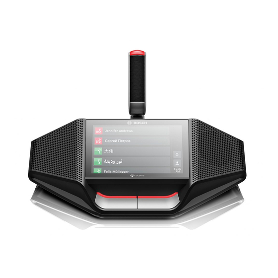
Page 38: Dicentis Microphones
| Mechanical installation of Contribution Devices DICENTIS DICENTIS Microphones Both the DCNM‑HDMIC High Directive Microphone and DCNM-MICL/S Stem Microphone are typically used with the DICENTIS devices. Figure 7.5: DCNM‑HDMIC and DCNM‑MICS / DCNM‑MICL front and bottom view Number Description LED indicator. - Page 39 The microphone can be easily connected to the DICENTIS devices: Figure 7.6: DCNM‑HDMIC or DCNM-MICS / DCNM-MICL connection To do so: Gently guide the connection guidance (4) into the DICENTIS device microphone connector (9). Gently push the connector plug (6) into the device microphone connector (9) until the connection lock (5) fits/click into place.
-
Page 40: Dcnm-Mmdsp Anti-Reflection Foil
The name card holder (1) can be used to permanently display the participant’s name on the rear of a DICENTIS multimedia Device. The name card holder has two magnets (2) that allow it to be easily attached to, and removed from, the rear of the device. -
Page 41: Installation Test
Not to do so could result in a system malfunctioning. Each DICENTIS device has its own built‑in diagnostics, which can be used for faultfinding. The diagnostics starts as soon the DICENTIS device is powered on. The DICENTIS Conference System does not have to be configured with, and connected to, the system controller PC. - Page 42 | Installation Test DICENTIS – Downloading devices is not covered in this manual. Refer to the DICENTIS configuration manual on how to download the devices. Customer service If a fault cannot be resolved, please contact your supplier or system integrator, or go directly to your Bosch representative.
- Page 44 Bosch Security Systems B.V. Torenallee 49 5617 BA Eindhoven Netherlands www.boschsecurity.com © Bosch Security Systems B.V., 2016...
Need help?
Do you have a question about the DICENTIS and is the answer not in the manual?
Questions and answers
why is it after setting dicentis system, i cant get languages on the microphone but i only get lauanguages on the receiver. what might be causing this and how to solve it?
Languages may not be available on the Bosch DICENTIS microphone but only on the receiver because the language is not configured as a Dante source or "Send to Dante" in the DICENTIS system. If a language is not set up correctly, it will not appear with a green checkmark in the Dante Controller, preventing it from being transmitted to the microphone.
To resolve this issue:
1. Ensure that the language is configured as a Dante source or "Send to Dante" in DICENTIS.
2. Verify that the correct DanteTM I/O (DCNM-LDANTE) license is applied for each language output.
3. Check that the Dante Controller is not running on the same PC as the DICENTIS services if the PC has two Ethernet cards, as this can cause connection issues.
4. Confirm that the number of devices in the system is equal to or greater than the number of languages provided by DICENTIS to ensure proper floor filling.
This answer is automatically generated