Bosch DICENTIS Manual
- Configuration manual (134 pages) ,
- Software manual (99 pages) ,
- Hardware installation manual (80 pages)
Advertisement
About this manual
The purpose of this manual is to provide information required for installing the DICENTIS Wireless Conference System.
- Please read this manual carefully before installing any of the products of the DICENTIS Wireless Conference System.
- Retain all documentation supplied with the products for future reference.
- This installation manual is available as a digital document in the Adobe Portable Document Format (PDF).
- For more information, refer to the product related information on:www.boschsecurity.com > Country of your choice > Conference Systems > DICENTIS Wireless Conference System
Intended audience
This hardware installation manual is intended for installers of a DICENTIS Wireless Conference System.
Alerts and notice signs
Four types of signs can be used in this manual. The type is closely related to the effect that may be caused if it is not observed. These signs - from least severe effect to most severe effect - are:
 Notice!
Containing additional information. Usually, not observing a 'notice' does not result in damage to the equipment or personal injuries.

The equipment or the property can be damaged, or persons can be lightly injured if the alert is not observed.

The equipment or the property can be seriously damaged, or persons can be severely injured if the alert is not observed.

Not observing the alert can lead to severe injuries or death.
System overview
The DICENTIS Wireless Conference System is a "standalone" IP based system. It uses WiFi IEEE 802.11n for wireless distribution and processing of audio and data signals.
Typical DICENTIS Wireless Conference System
A typical DICENTIS Wireless Conference System (see following figure and numbering on next page) consists of:
- a Wireless Access Point (1), including the power supply adapter (2),
- Wireless Devices (4 + 5), including Battery Pack and microphone,
- a tablet device (7) for operational use, or
- a PC/laptop (8) for operational use, and licensing/updating the system software (if the PC is not required for operational use, it can be disconnected from the system after licensing/updating the system software).
- a Battery Pack Charger (6).

Figure 3.1: Typical DICENTIS Wireless Conference System
Typical extended DICENTIS Wireless Conference System
A typical extended DICENTIS Wireless Conference System (see the following figure and numbering on the next page) has an additional Ethernet network switch/video switch (10) and HD Conference Dome (11).

Figure 3.2: Typical extended DICENTIS Wireless Conference System
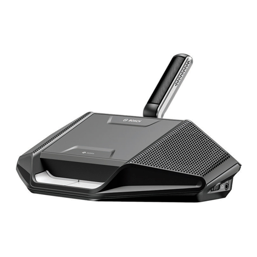
- The Wireless Access Point (DCNM‑WAP) is the central component of the DICENTIS Wireless Conference System. It is used for:
- hosting a web browser interface for licensing, configuring and controlling the system.
- controlling the system audio, and routing the audio from and to the Wireless Devices.
- environment wireless channel scanning. The best available wireless channel will be chosen for the system.
- Camera control. It controls the optional connected switch (10) and cameras (11). Note: If more than one camera is connected to the system, a video switch (13) is required.
- AC/DC power supply adapter (supplied with the DCNM‑WAP).
- (Optional connections) Audio line input and audio line output.
- Wireless Device (DCNM‑WD): used as a single-use, dual-use or chairperson Wireless Device, including Battery Pack and microphone (both to be ordered separately)
- Participants can use the Wireless Device to participate in a discussion.
- Wireless Device Extended (DCNM‑WDE): used as a single-use, dual-use or chairperson Wireless Device, extended with Near Field Communication (NFC) reader for user identification and 4.3" capacitive touch screen, including Battery Pack and microphone (both to be ordered separately).
- Participants can use the Wireless Device Extended to participate in a discussion.
- Charger (DCNM‑WCH05): used to charge the Battery Packs of the Wireless Devices.
- Tablet device:
- Used to configure and control the system via the website hosted on the DCNM‑WAP.
- PC/Laptop:
- Used to configure and control the system if a tablet is not used.
- Used to license and update the systems firmware, as required.
- Ethernet cable/PoE+:
- Used for connection to the Ethernet.
- PoE+ is used for powering the DCNM‑WAP.
- Ethernet network switch:
- Routes the system data via Ethernet.
- OptionalHD Conference Dome:
- Captures the video of a speaking participant.
- Coax cable: transports the signal between the camera and the video switch (13).
- Video switch:
- TV-One CORIOmatrix mini and the Kramer MV-6 are supported.
- Connected between the display (14) with the Ethernet network switch (10).
- Display: Shows the speaking participant.
DICENTIS Wireless Conference System system with redundant WAP
The system can be configured with a redundant DCNM‑WAP provided the following conditions are met. The procedure for subscribing a redundant DCNM‑WAP is described in the Configuration manual.
- Preferably both WAPs are connected to an Ethernet network switch with a DCN multimedia System Network Cable or a standard network cable, and the Ethernet network switch is connected to a laptop or PC.
Note: The use of an Ethernet network switch and cabling are preferred during the subscription process, because this makes it easier to access and subscribe the WAPs. When subscription of the secondary WAP is complete, the Ethernet network switch and cabling can be removed if it is no longer required.
- The WAPs are correctly positioned (there should be a minimum distance of one meter and a maximum distance of three meters between the two WAPs).
- The WAPs are powered up and the Wireless Conference System is operational.
- Both WAPs have been correctly configured in the Installation Wizard and have unique names for:
- Network name (SSID)
- WPA2 key
- Hostname
- Both WAPs are set to the Standalone (factory default).
- The applicable licenses are available for the primary WAP and the secondary WAP (the redundant WAP requires its own set of licenses for features such as voting and dual-use at seat to continue working if the primary WAP fails).
- If recording/playback and PA are required, make sure audio connectors are connected to the balanced In/Out connectors of both the primary and secondary WAP.
- If access to the API (for showing voting results) and web browser settings is required, make sure Ethernet cables are connected to both the primary and secondary WAP.
Extended system requirements
The following requirements are valid if you want to extend your system with a network switch or cameras:
- Network switch and camera installation instructions are not part of this installation manual; please consult the product related documentation of the supplier.
- A video switch is required, when more than one camera is required. The following switches are supported:
- tvONE CORIOmaster mini C3-510
- Kramer MV-6 3G HD-SDI Multiviewer
- A DHCP server is needed for both the Wireless Access Point and the cameras.
Cameras
Typical, the Bosch HD Conference Dome is used. Refer to product related information on: www.boschsecurity.com > Country of your choice > Conference Systems > DICENTIS Wireless Conference System > HD cameras and accessories.
Planning
Use the guidelines in this section to plan the design and installation of your DICENTIS Wireless Conference System.
Unpacking
This equipment should be unpacked and handled with care. If an item appears to be damaged, notify the shipper immediately. If any items are missing, notify your Bosch representative. The original packaging is the safest container in which to transport products and can be used to return products for service if necessary.
System design planning
- If the DICENTIS Wireless Conference System is used in an area where there are other WiFi access points within (30 m) range of the DCNM‑WAP, you should apply frequency planning. Put the other access points on manual frequency selection to prevent the WiFi networks from trying to use the same frequency.
- Probing of other WiFi devices (such as smart phones or tablets) to the DICENTIS Wireless Conference System can cause unstable functionality. Therefore it is strongly recommended that these WiFi devices are connected to dedicated WiFi access points. These WiFi access points must have sufficient capacity for WiFi connection of all nearby WiFi devices.
- The maximum distance between the DCNM‑WAP and the Wireless Devices can be reduced by RF absorbance of signal radiation of certain building materials e.g. concrete, and or metal.
- When using a smart device with a wireless connection to the system, the maximum number of connected Wireless Devices must be reduced. With 1 smart device, 119 Wireless Devices can be controlled, and up to 3 smart devices can be used to control 117 Wireless Devices. Otherwise use a wired connection to the DCNM‑WAP to maintain the maximum number of 120 Wireless Devices.
Installation planning
- Make sure you have all components for installing and connecting the DICENTIS Wireless Conference System (see System overview).
- Familiarize yourself with the products capabilities of the DICENTIS Wireless Conference System (see System overview, and the paragraphs Control capacity and Coverage area in this section).
- Use only Bosch specified installation materials and tools (see Additional components).
- Determine the end‑user requirements, typical questions are:
- The number of seats?
- How many chairpersons are required?
- Should the Wireless Devices be in dual‑use mode?
- Is voting required?
- Is identification required?
- Is camera control required?
- Calculate the number of seat positions. This depends on, the number of participants, the number of chairpersons and whether the Wireless Devices will be in single‑use or dual‑use.
- Example: The system requires 25 participants and one chairperson. Two participants will use one Wireless Devices. Use the following formula to calculate how many devices are required: Round up (participants/2) + chairperson.
In this example 25/2 = 12.5 > Round up (12.5) = 13 + 1 = 14 Wireless Devices.
- If camera control is a required, the license DCNM-LCC must be added to the system. Do not forget to add the cameras to the system. The Bosch HD Conference Dome is supported.
- Decide if, and which type of, cabling is required. See System overview.
- Decide on how to power the Wireless Access Point (DCNM‑WAP). See System overview:
- Via the AC/DC power supply adapter (supplied with the DCNM‑WAP). Or:
- Via Power over Ethernet (PoE). Or:
- Via Ethernet switch. Or:
- DICENTIS (Audio) Powering Switch.
- Provide a mains power supply connections nearby the equipment which requires mains power supply.
- Decide on how to power the other devices used in the system (i.e. Ethernet switch, cameras etc.). See System overview,:
- Via their own (mains) power supply provision. Or:
- Via Power over Ethernet (PoE), if possible.
- Decide on how, and where, to install the Wireless Access Point (DCNM‑WAP). See Installation Wireless Access Point:
- Wall, ceiling. Or:
- Tripod floor stand.
- Decide where, and how to place, the Wireless Devices (DCNM‑WD and/or DCNM‑WDE). See Installation Wireless Devices and Accessories.
- Decide on how, and where to attach the Charger to a wall. See Charger.
Control capacity
- The Wireless Access Point (DCNM‑WAP) can control a maximum of 120 wireless connections. A wireless connection can be:
- a Wireless Device (DCNM‑WD or DCNM‑WDE), or
- a Wireless Device with web browsing functionality, such as a tablet or laptop.
- A maximum of one DCNM‑WAP can be used to control the system.
Coverage area
- All Wireless Devices need to be in the WiFi coverage area of the DCNM‑WAP.
- For a maximum WiFi coverage area, the DCNM‑WAP can be placed on a central location in the room.
- The DCNM‑WAP has a typical WiFi coverage area of30 m by 30 m.
802.11n specification
The DICENTIS Wireless Conference System network is based on the 802.11n specification for WiFi technology. Devices that comply to the 802.11n specification operate in frequency bands between 2.4000 and 2.4835 GHz and 5.180 and 5.700 GHz.
Notice!
Although the system operates on frequencies which are license free world wide, you must be aware of country specific limitations and follow them.
Additional components
The following additional components can be used with the DICENTIS Wireless Conference System, as required:
6.3 mm jack cables – These cables are required if you want to connect optional audio equipment to the audio line input and/or audio line output of the Wireless Access Point (DCNM‑WAP), such as microphones and a sound reinforcement system.
CAT5e cables - These cables are required if you want to connect a PC/Laptop to the Wireless Access Point (DCNM‑WAP) for running the web browser interface and connecting a switch and HD Conference Domes.
Installation Wireless Access Point
Use the following steps to install the Wireless Access Point (DCNM‑WAP).
- Make sure all equipment is available as described inDelivered with product.
- Optional set the "Brand logo" in the correct orientation.
- Connect the cabling and install the Wireless Access Point to the wall/ceiling or tripod floor stand.
- Power on the Wireless Access Point.
Delivered with product
The Wireless Access Point (DCNM‑WAP) is shipped with the following parts:
| Quantity | Components |
| 1 | DCNM‑WAP Wireless Access Point |
| 1 | AC/DC power supply adapter. Including: AC plug‑AU, AC plug‑UK, AC plug‑EU, AC plug‑US, GE24I48‑R7B |
| 1 | Mounting bracket |
| 1 | DVD with manuals and software |
| 1 | Safety instructions |
Brand logo
The orientation of the logo could be changed.
![]()
Figure 5.1: Change logo orientation
Cabling and wall/ceiling/tripod floor stand installation
The Wireless Access Point is provided to be installed to a wall, a ceiling or on a tripod floor stand. Take care of the installation location regarding the wireless signal coverage area between the Wireless Access Point and the Wireless Devices. See Planning.
Do not open the Wireless Access Point. Any hardware change makes the product certificates invalid. Only qualified personnel may open the Wireless Access Point.
Cable connections:

Figure 5.2: DCNM‑WAP front and bottom view
- Connect an external balanced audio line input (4), if required.
- Connect the balanced audio line output (6) to an external audio system, if required.
- Connect the Ethernet (PoE) (2) or AC/DC power supply adapter (3).
For detailed connection description, see the "Power on / connection and indicator" paragraph at the end of this section.
Wall or ceiling installation
Use the mounting bracket to attach the Wireless Access Point to a wall or ceiling.

Figure 5.3: Mounting to a wall or ceiling
Tripod floor stand installation
Use the mounting bracket to install the Wireless Access Point on a Bosch LBC1259/01 universal tripod floor stand.

Figure 5.4: Mounting on a tripod floor stand
Power on / connections and indicators
The DCNM‑WAP is powered via one of the three power supply sources marked with an * in the table below. As soon the power supply is provided, the Wireless Access Point is powered on, and the six LEDs (1) on the front side are all on.
- To configure the DCNM‑WAP, refer to the configuration manual of the DICENTIS Wireless Conference System.

Figure 5.5: DCNM‑WAP front and bottom view

| Item | Description | |
| 1 | 2x 3 status LED: Gives detailed information about the condition of the Wireless Access Point and the wireless network. Refer to the software configuration manual of the DICENTIS Wireless Conference System. | |
| 2 | Network / DCN multimedia / PoE socket. Powered with:
Connects the Wireless Access Point point to the wired Ethernet network. For DCN multimedia System Network Cable, see Additional components. | |
| 3 |
| |
| 4 | Balanced audio line output socket: Connection to a public address system, audio mixers or to a voice logging system for audio registration of all spoken conference proceedings. Use standard line output cabling. 6.3mm (1/4") jacks with the following pinning: Tip: Live (+) Ring: Return (-) Sleeve: Shield | |
| 6 | Balanced audio line input socket: Connection from audio source. Use standard line output cabling. 6.3 mm (1/4") jacks with the following pinning: Tip: Live (+) Ring: Return (-) Sleeve: Shield | |
| 5 | Reset‑to‑default button: Sets the DCNM‑WAP to factory default values. Press and hold for at least 8 seconds to set all settings to factory default. | |
See also
- Planning
- Additional components
Installation Wireless Devices and Accessories
The Wireless Devices are used to add participants to a discussion. See System overview,, if required.
Delivered with product
- The DCNM‑WD and DCNM‑WDE are shipped without (accessory) parts.
Installation
The Wireless Devices are free‑standing (table-top use). No mechanical installation, other than the accessories as described below, is required.
If a Wireless Device Extended is moved from a warm and humid environment to a cold environment there is a possibility that some condensation can form on the display. To prevent this from happening, make sure each Wireless Device Extended is given sufficient time to acclimatize.

DCNM‑WDE and DCNM‑WD top, rear and base view
Do not open the Wireless Device. Any hardware change makes the product certificates invalid. Only qualified personnel may open the Wireless Devices.
Installation of accessories
Follow below steps to install the required accessories to, and placing of, the Wireless Devices.
These steps are a summary:
- Check that all equipment is available.
- For your reference, see the Wireless Device figure and table in this section.
- Install the Battery Pack (15) in each Wireless Device to be used. Refer to Battery Pack.
- Attach the microphones to the Wireless Devices (11). Refer to Microphones.
- Place the Wireless Devices in the coverage area of the Wireless Access Point (DCNM‑WAP). SeePlanning, if required.
Connection, indicators and controls
The following table gives an overview of the Wireless Device items and functionality (Refer to the numbers in the previous figure).
Connection and configuration of the Wireless Devices within the system is done via DCNM‑WAP. Refer to the software configuration manual of the DICENTIS Wireless Conference System.
| Item | Description |
| 1 | Near Field Communication (NFC) user identification (DCNM‑WDE only). Used to identify the (logon) participant with an NFC Tag. |
| 2 | 4.3" capacitive touch screen (DCNM‑WDE only). |
| 3 | Loudspeaker. |
| 4 + 5 | Combined button, depending on software configuration:
|
| 6 | LED (lightguide) microphone request button (5). |
| 7 | Microphone request button (single-use, chairperson or dual-use mode). |
| 8 | LED (lightguide) microphone request button (7). |
| 9 | Headphone volume control. |
| 10 | 3.5 mm stereo jack for headphone. |
| 11 | Microphone (input) connector. |
| 12 | Red battery‑low LED indicator. The LED is flashing when the Battery Pack of the Wireless Device is empty within 1 hour. Charging the Battery Pack is advised. See Battery Pack and Charger. |
| 13 | Yellow out‑of‑range LED indicator. The LED is on when the Wireless Device is not (yet) connected with the Wireless Access Point (DCNM‑WAP). Move the Wireless Device within the coverage area of the DCNM‑WAP. The LED is flashing when the Wireless Device is trying to make a connection with the Wireless Access Point (DCNM‑WAP. See Planning. |
| 14 | (DCNM‑WLIION) Battery Pack locking clip. See Battery Pack. |
| 15 | (DCNM‑WLIION) Battery Pack. See Battery Pack. |
| 16 | De‑init button. When push (>2 seconds), the subscription between the Wireless Device and Wireless Access Point is removed. |
| 17 | (DCNM‑WLIION) Battery Pack capacity test button. See Battery Pack. |
| 18 | (DCNM‑WLIION) Battery Pack capacity LED (5x) indicators. See Battery Pack. |
See also
- Battery Pack
- Microphones
- Planning
- Charger
Microphones

Figure 6.1: DCNM‑HDMIC or DCNM‑MICx to Wireless Device connection
Both the DCNM‑HDMIC High Directive Microphone and DCNM-MICL/S Stem Microphone are typically used with the DICENTIS devices.
 1
1Figure 6.2: DCNM‑HDMIC and DCNM‑MICS / DCNM‑MICL front and bottom view
| Number | Description |
| 1 | LED indicator. |
| 2 | Microphone grill. |
| 3 | Adjustable stem (DCNM‑MICS / DCNM‑MICL). |
| 4 | Connection guidance. |
| 5 | Slider guidance. |
| 6 | Connector plug. |
| 7 | Lock-slider for lock release (Press and shift to release). |
| 8 | Lock. |
| 9 | Device female connector (see following figure). |
How to connect or remove the microphone
The microphone can be easily connected to the DICENTIS devices:

Figure 6.3: DCNM‑HDMIC or DCNM-MICS / DCNM-MICL connection
To do so:
- Gently guide the connection guidance (4) into the DICENTIS device microphone connector (9).
- Gently push the connector plug (6) into the device microphone connector (9) until the connection lock (5) fits/click into place.
- To remove the microphone from the device: Shift lockslider (7) towards the device and hold in place lock release (8) and pull out the microphone.
Battery Pack
The Battery Pack (DCNM‑WLIION) provides the power supply of the Wireless Devices (DCNM‑WD and DCNM‑WDE).
Refer to Installation Wireless Devices and Accessories, if required.
Battery charging and handling
- Charge the Battery Pack (DCNM‑WLIION) immediately on receipt.
- Only use the approved Charger (DCNM‑WCH05) to charge the Battery Pack (DCNM‑WLIION).
- Immediately recharge the Battery Pack (DCNM‑WLIION) when the remaining capacity drops below 5%. Refer toCharger.
- Empty battery packs must be charged within 30 days.
- Do not leave an empty Battery Pack in a Wireless Device.
Delivered with product
- The DCNM‑WLIION is shipped without (accessory) parts.
The lifetime of a Battery Pack can be severely affected if it is completely drained. If a Wireless Device is put in storage or is not being used for a while, remove the Battery Pack and place it in the approved Charger.
How to install the Battery Pack

Figure 6.4: Wireless Device bottom view including Battery Pack

Figure 6.5: DCNM‑WLIION Battery Pack top (1) and rear (3) view.
- Turn the Wireless Device up‑side‑down.
- Turn the Battery Pack to top view (1) and hook the securing nocks (6) in the Wireless Device battery compartment.
- Gently push down the Battery Pack until itlocks (2) into the Wireless Device Battery Pack compartment.
How to remove the Battery Pack
- Turn the Wireless Device up‑side‑down.
- Remove the Battery Pack in reverse order by push‑and‑hold the locking clip (2) and gently pushing up the Battery Pack.
- Take out the Battery Pack.
Connections and indicators
The following table gives an overview of the Battery Pack connections and indicators (refer to the numbers in the previous figure in this section).
| Item | Description |
| 1 | Top view. |
| 2 | Locking clip mechanism: Locks the Battery Pack in the Wireless Device. |
| 3 | Rear view. |
| 4 | Battery Pack capacity/condition test button: Pushing the button lights 0 to 5 capacity LED indicators, depending on the capacity time left (5). |
| 5 | Green Battery Pack capacity LED indicators (5x): Showing the capacity/ condition of the Battery Pack. From left to right (5‑1), typical each LED indicates a capacity time in hours left:
|
| 6 | Securing nock (3x). Secures the Battery Pack in the Wireless Device. |
| 7 | Power supply and charging connector. |
Charger
The Charger (DCNM‑WCH05) is used for (and can be used for connection to IT power distribution systems):
- Charging the Battery Pack (DCNM‑WLIION).
- One Charger can charge a maximum of 5 Battery Packs at the same time.
Delivered with product
- The DCNM‑WCH05 is shipped with the following parts:
- 1x Mains power cable.
- 1x Loop‑through mains power cable.
- 1x Mounting bracket.
- 1x Safety instructions.

Figure 6.6: Charger DCNM‑WCH05

| Item | Description | |
| 1 | Ventilation grilles: Do not obstruct the ventilation grilles. The Charger must remain within the specified temperature range. See Charger (DCNM-WCH05). | |
| 2 | Battery Pack container (5x): Each container could hold a Battery Pack (DCNM‑WLIION). | |
| 3 | Charging level LEDs: Shows the charging level of the Battery Pack: From left to right (5‑1), typical each LED indicates a capacity time in hours (left):
| |
| 4 | Power on/off LED: Is on when the power cable is connected to Charger and the other end is connected to the mains power supply. | |
| 5 | Mains power supply socket/inlet. The maximum current handling of the inlet is 10A. Therefore there is a limitation of the number of loop‑through Chargers. For details, see the Mains power connection / loop‑through paragraph in this section. | |
| 6 | Mains power supply loop‑through socket: The loop‑through mains socket allows a maximum number of Chargers to be connected in series to share from the same mains power supply outlet. For details, see the Mains power connection / loop‑through paragraph in this section. | |
Installation
Do not open the Charger. Electrical discharges from the Charger can kill you.
This is a class A product. In a domestic environment this product may cause radio interference in which case the user may be required to take adequate measures.
Do not obstruct the ventilation grilles. A blockage of the ventilation grilles can cause a risk of fire and malfunction/defect of the Charger and Battery Pack.
The Charger (DCNM‑WCH05) must be fixed installed to the wall by qualified service personnel, using the supplied mounting bracket. Disassembly is also only allowed by qualified service personnel.

Figure 6.7: Installation to a wall
When installing more than one Charger next to each other, be sure that:
- The vertical distance between two brackets is at least340 mm (refer to d1 in the next figure).
- The horizontal distance between two brackets is at least195 mm (refer to d2 in the next figure).
![]()

Mains power supply connection / loop‑through
- Connect a locally approved mains power cord to the Charger mains power supply socket/ inlet (5).
- With the loop‑through mains power supply socket (6), you can loop‑through Chargers:
- If the mains power supply is100‑127 V(AC), 50/60 Hz, a maximum of 2 Chargers can be looped‑through.
- If the mains power supply is220‑240 V(AC), 50/60 Hz, a maximum of 5 Chargers can be looped‑through.
Install/remove the Battery Pack
- Install the Battery Pack until it locks in the Charger, as illustrated in the next figure.
- Remove the Battery Pack in the reversed order by gently take‑out the Battery Pack.
- Connect the mains power supply to the Charger to power on the Charger and to start the charging process.
- Power LED (4) is on when receiving mains power supply.
- See the charging level LEDs (3) which indicate the charging level of the Battery Pack.
![]()
Figure 6.8: Placing of the Battery Pack

Charging time
- The typical charging time of one Battery Pack is3 hours.
- The LEDs (3) showing the charging level of the Battery Pack.
- Remove the Battery Pack as soon it is fully charged (All LEDs (3) are on).
See also
- Charger (DCNM-WCH05)
System power on and configuration
Consult the configuration manual of the DICENTIS Wireless Conference System for power on and configuration details of the Wireless Access Point and Wireless Devices.
- For documentation, refer to the DICENTIS Wireless Conference System product related information on: www.boschsecurity.com > Country of your choice > Conference Systems > DICENTIS Wireless Conference System
Maintenance
The DICENTIS Wireless Conference System requires minimum maintenance. To ensure for trouble‑free operation, clean and inspect the system components on a regular basis:
Cleaning
Do not use alcohol, ammonia, petroleum solvents or abrasive cleaners to clean the system components.
- Clean the Wireless Devices with a soft cloth moistened very slightly with a weak soap and water solution.
- Clean the touch screen of the Wireless Devices with a dry soft cloth.
- Wait until the Wireless Devices are fully dry before reconnecting them to the system cabling.
- Clean the Wireless Access Point and Charger with a dry soft cloth, as required.
Inspect components
- Check all DICENTIS Wireless Conference System components for signs of wear and tear. Replacement products can be ordered from your Bosch representative, if required.
- Check the Wireless Devices microphone buttons for correct operation. They should not be loose or stick when operated.
- Check all connectors of the Wireless Access Point and system cabling for damage.
- Check the functionality of, and charge, the Battery Pack of the Wireless Devices on a regular base.
- Check the functionality of the Charger on a regular base.
Service
If a defect cannot be resolved, please contact your supplier or system integrator, or contact your Bosch representative directly.
Technical data
Wireless Access Point (DCNM-WAP)
Technical specifications
Radio
| WIFI standard | IEEE 802.11n |
| Frequency Range | 2.4 GHz and 5 GHz (ISM license free) |
Mechanical
| Mounting | Ceiling, Wall or Tripod floor stand (using included bracket) |
| Dimensions (H x W x D) with bracket | 285 x 202 x 65 mm (11.2 x 8.0 x 2.6 in) |
| Weight: with bracket without bracket | 958 g (2.11 lb) 725 g (1.60 lb) |
| Color | Light grey (RAL 000 7500) |
Electrical
| Supply voltage (PSU) | 100‑240 Vac 50‑60 Hz in 48 Vdc out |
| PoE | 802.3af, 802.3at - type 1 mode A (endspan), mode B (midspan) |
| DCNM system supply | 48 Vdc |
| Power consumption | 10 W |
| Frequency response | 80 Hz - 20 kHz |
| THD at nominal level | <0.1% |
| Dynamic range | >98 dBA |
| Signal‑to‑noise ratio | >96 dBA |
| Ethernet | 1000Base‑T IEEE 802.3ab |
Audio inputs
| Jack nominal | -18 dBV |
| Jack maximum | +18 dBV |
Audio outputs
| Jack nominal | -18 dBV |
| Jack maximum | +20 dBV |
Environmental
| Operating temperature | 5 ºC to +45 ºC (41 ºF to +113 ºF) |
| Storage and transport temperature | -20 ºC to +70 ºC (-4 ºF to +158 ºF) |
| Relative humidity | < 95%, > 5% |
Approvals and certifications
| EU | CE, WEEE |
| US | UL, FCC |
| CA | CSA, ICES‑003, EPS |
| KR | KC |
| AU/NZ | RCM, MEPS |
| RU/KZ/BY | EAC |
| JP | PSE, MIC |
| CN | China RoHS, CCC, CMIIT |
| SA | SASO |
| BR | ANATEL |
Wireless Devices (DCNM-WD and DCNM-WDE)
Technical specifications DCNM-WD
Mechanical
| Mounting | Tabletop |
| Dimensions (H x W x D) without microphone | 72 x 259 x139 mm (2.8 x 10.2 x 5.5 in) |
| Weight: DCNM‑WD DCNM‑WD + Battery Pack | 590 g (1.30 Lb) 1051 g (2.32 lb) |
| Color (top and base) | Traffic black (RAL 9017) |
Electrical
| Supply voltage (battery pack) | 7.5 Vdc |
| Power consumption | 4.5 W |
| Operating time DCNM‑WD | > 24 hours (20% speech, 80% listening) |
| Frequency response | 100 Hz – 20 kHz) (-3 dB at nominal level) |
| THD at nominal level | < 0.1% |
| Dynamic range | > 90 dB |
| Signal‑to‑noise ratio | > 90 dB |
| Headphone load impedance | > 32 ohm <1k ohm |
| Headphone output power | 15 mW |
Radio
| WIFI standard | IEEE 802.11n |
| Frequency Range | 2.4 GHz and 5 GHz (ISM license free) |
| Audio inputs | |
| Nominal microphone input | 80 dB SPL according IEC60914 |
| Maximum microphone input | 110 dB SPL according IEC60914 |
Audio outputs
| Loudspeaker nominal output | 72 dB SPL at 0.5 m |
| Loudspeaker maximum output | 80 dB SPL |
| Headphone nominal output | 0 dBV |
| Headphone maximum output | 3 dBV |
Environmental
| Operating temperature | 5 ºC to +45 ºC (41 ºF to +113 ºF) |
| Storage and transport temperature | -20 ºC to +70 ºC (-4 ºF to +158 ºF) |
| Relative humidity | < 95%, > 5% |
Technical specifications DCNM-WDE
Audio outputs
| Loudspeaker nominal output | 72 dB SPL at 0.5 m |
| Loudspeaker maximum output | 80 dB SPL |
| Headphone nominal output | 0 dBV |
| Headphone maximum output | 3 dBV |
Electrical
| Supply voltage (battery pack) | 7.5 Vdc |
| Power consumption | 4.5 W |
| Operating time DCNM‑WDE | > 20 hours (20% speech, 80% listening) |
| Frequency response | 100 Hz – 20 kHz) (-3 dB at nominal level) |
| THD at nominal level | < 0.1% |
| Dynamic range | > 90 dB |
| Signal‑to‑noise ratio | > 90 dB |
| Headphone load impedance | > 32 ohm <1k ohm |
| Headphone output power | 15 mW |
Radio
| WIFI standard | IEEE 802.11n |
| Frequency Range | 2.4 GHz and 5 GHz (ISM license free) |
| Audio inputs | |
| Nominal microphone input | 80 dB SPL according IEC60914 |
| Maximum microphone input | 110 dB SPL according IEC60914 |
General
| Screen size (DCNM‑WDE only) | 4.3 inch |
| Screen type (DCNM‑WDE only) | Capacitive multi‑touch |
| Supported contactless NFC tag (DCNM‑WDE only) | According to: ISO/IEC14443 Type A (from 106 kbps to 848 kbps. MIFARE 106kbps). |
Mechanical
| Mounting | Tabletop |
| Dimensions (H x W x D) without microphone | 72 x 259 x139 mm (2.8 x 10.2 x 5.5 in) |
| Weight: DCNM‑WDE DCNM‑WDE + Battery Pack | 670 g (1.47 lb) 1131 g (2.49 lb) |
| Color (top and base) | Traffic black (RAL 9017) |
Environmental
| Operating temperature | 5 ºC to +45 ºC (41 ºF to +113 ºF) |
| Storage and transport temperature | -20 ºC to +70 ºC (-4 ºF to +158 ºF) |
| Relative humidity | < 95%, > 5% |
Approvals and certifications
| EU | CE | |||
| US | FCC | |||
| CA | ICES‑003 | |||
| KR | KC | |||
| AU/NZ | RCM | |||
| RU/KZ/BY | EAC | |||
| JP | MIC | |||
| CN | China RoHS, CMIIT | |||
| SA | SASO | |||
| BR | ANATEL | |||
Battery Pack (DCNM-WLIION)
Technical specifications
Electrical
| Nominal output Voltage | 7.5 VDC |
| Capacity | 12800 mAh |
Mechanical
| Dimensions (H x W x D) | 99.9 x 136.5 x 22 mm (3.93 x 5.37 x 0.87 in) |
| Weight | 460 g (1.0 lb) |
| Color | Charcoal |
Environmental
| Operating temperature | 5 ºC to +45 ºC (41 ºF to +113 ºF) |
| Advised storage and transport temperature | -5 ºC to +35 ºC (23 ºF to +95 ºF) |
| Relative humidity | <75%, >5% |
Approvals and certifications
| EU | CE |
| US | UL, FCC |
| CA | CSA, ICES‑003 |
| KR | KC |
| AU/NZ | RCM |
| RU/KZ/BY | EAC |
| JP | PSE |
| CN | China RoHS |
| SA | SASO |
| BR | ANATEL |
| TH | TISI |
| Other | UN 38.3 |
Charger (DCNM-WCH05)
Technical specifications
Electrical
| Supply Voltage | 100-240 Vac +/- 10 % 50/60 Hz |
| Maximum power consumption | 300 W |
Mechanical
| Dimensions (H x W x D) | 340 x 195 x 82 mm (13.4 x 7.6 x 3.2 in) |
| Weight (without batteries) | 1.8 kg (3.97 lb) |
| Color | Traffic black (RAL 9017) |
Environmental
| Operating temperature | 5 ºC to +45 ºC (41 ºF to +113 ºF) |
| Storage temperature | -20 ºC to +70 ºC (-4 ºF to +158 ºF) |
| Relative humidity | < 95%, > 5% |
Approvals and certifications
| EU | CE, WEEE |
| US | UL, FCC |
| CA | CSA, ICES‑003 |
| KR | KC |
| AU/NZ | RCM |
| RU/KZ/BY | EAC |
| JP | PSE |
| CN | China RoHS |
| SA | SASO |
High Directive Microphone (DCNM-HDMIC)
Technical specification
Electrical
| Power supply | 5 VDC |
| Power consumption | 0.1 W |
| Bandwith | 100 Hz – 15 kHz according IEC 60914 |
| Dynamic range | > 96 dB |
| Nominal input | 80 dB SPL |
| Maximum input | 110 dB SPL |
| Equivalent noise | 12 dB SPL |
Mechanical
| Mounting | Plug and fasten into DICENTIS device and DICENTIS Wireless Devices. |
| Dimensions (H x W x D) | 108 x 21.5 x 60 mm (4.25 X 0.85 x 2.36 in) |
| Weight | 0.035 kg (0.077 lb) |
| Color | Traffic black RAL 9017 Pearl light grey RAL 9022 |
Environmental
| Operating temperature | 0 ºC to +45 ºC (32 ºF to +113 ºF) |
| Storage and transport temperature | -20 ºC to +70 ºC (-4 ºF to +158 ºF) |
| Relative humidity | < 95%, > 5% |
Microphones (DCNM-MICx)
Technical specifications
Electrical
| Power supply | 5 VDC |
| Power consumption | 0.1 W |
| Bandwidth | 125 Hz – 15 kHz according IEC 60914 |
| Dynamic range | >100 dB |
| Nominal input | 85 dB SPL |
| Maximum input | 115 dB SPL |
| Equivalent noise | 15 dB SPL |
Mechanical
| Mounting | Plug and fasten into DICENTIS device and DICENTIS Wireless Devices. |
| Length: DCNM‑MICS (without connector) DCNM‑MICL(without connector) | 310 mm (12.21 in) 480 mm (19.90 in) |
| Connector | 77.15 x 60.47 mm (3.40 x 2.38 in) |
| Weight: DCNM‑MICS DCNM‑MICL | 91 g (0.20 lb) 108 g (0.24 lb) |
| Color: DCNM‑MICS / DCNM‑MICL | Traffic black RAL 9017 Pearl light grey RAL 9022 |
Environmental
| Operating temperature | 0 ºC to +45 ºC (32 ºF to +113 ºF) |
| Storage and transport temperature | -20 ºC to +70 ºC (-4 ºF to +158 ºF) |
| Relative humidity | < 95%, > 5% |
Safety
Prior to installing or operating products, always read the Important Safety Instructions which are available as a separate multilingual document: Important Safety Instructions (Safety_ML). These instructions are supplied together with all equipment that can be connected to the mains supply.
Old electrical and electronic appliances

Electrical or electronic devices that are no longer serviceable must be collected separately and sent for environmentally compatible recycling (in accordance with the European Waste Electrical and Electronic Equipment Directive).
To dispose of old electrical or electronic devices, you should use the return and collection systems put in place in the country concerned.
Battery Pack
Please take notice of the safety instructions printed on the label of the Battery Pack (DCNM‑WLIION
Charger
The Charger (DCNM‑WCH05) must be fixed installed to the wall by qualified service personnel, using the supplied mounting bracket. Disassembly is also only allowed by qualified service personnel.
Wireless Access Point
If you want to attach the Wireless Access Point (DCNM‑WAP) to a wall, it must be correctly installed as described in this manual. Refer to Installation Wireless Access Point.
Notice!
Changes or modifications made to this equipment, not expressly approved by Bosch Security Systems B.V. may void the FCC authorization to operate this equipment.
Notice!
The Wireless Devices and the Wireless Access Point comply with FCC radiation exposure limits set forth for an uncontrolled environment. The Wireless Devices and the Wireless Access Point should be installed and operated with minimum distance of 20 cm to your body.
Bosch Security Systems B.V.
Torenallee 49
5617 BA Eindhoven
Netherlands
Documents / Resources
References
Download manual
Here you can download full pdf version of manual, it may contain additional safety instructions, warranty information, FCC rules, etc.
Advertisement


Need help?
Do you have a question about the DICENTIS and is the answer not in the manual?
Questions and answers