Table of Contents
Advertisement
Advertisement
Table of Contents

Subscribe to Our Youtube Channel
Related Manuals for Process Technology DQ15D


Summary of Contents for Process Technology DQ15D
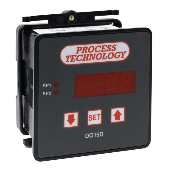
- Page 1 DQ15D Digital Temperature Control Installation, Operation and Calibration Manual 7010 Lindsay Dr., Mentor, OH 44060 • Phone: 440-974-1300 U.S./Canada: 800-621-1998 • FAX: 440-974-9561 P.O. Box 660, Mentor, OH 44061 www.process-technology.com M-34-01 DQ15D Manual Revision - Date: 01 - 04/23/08...
- Page 2 ONLY. Electrical Noise / Interference Process Technology electronic controls are engineered, tested and manufactured to conform to Europe’s CE levels of electrical noise and interference found in typical industrial installations. It is always possible for electrical noise and interference to exceed the level of designed-in protection.
-
Page 3: Table Of Contents
L, Set Point Limit ..............21 F1, SP2 and U7 Disable ............22 F2, Heating or Cooling Switch ..........22 F3, Alarm On/Off Switch ............22 F4, Unit Display Enable ............22 M-34-01 DQ15D Manual Revision - Date: 01 - 04/23/08... -
Page 4: Control Outputs
DQ15D Specifications 2 wire- 1000 ohm RTD TCR (alpha), 0.00385 ohm/ohm/°C Standard Input RTD Self Heating Coefficient: 5° C/w in 0.2 m/s water; 200° C/w in 1 m/s air measurement current, 0.1 to 0.2 mA -40 to 1000°F (-40 to 538°C) Input Range °F or °C field selectable... -
Page 5: General Description
General Description General Description Installation The DQ15D digital temperature DQ15D is for indoor use only. control is a programmable and Unpack and inspect DQ15D for microprocessor-based controller damage upon receipt. Shipping designed to operate two relays for damage claims must be made temperature control. -
Page 6: Wiring
This section provides wiring notes inserting the control in the panel. for Power Heating/Cooling relays Insert DQ15D through the and Over Temperature Protection. prepared opening and slide the Over Temperature Protection retaining collar over the case from Component failure in a temperature the rear of the panel. -
Page 7: Power, Heating/Cooling
• Relay connection wires is approximately 1°F for every 65 ft. Procedure DQ15D is intended for a single power source. Refer to the Power, Warning Heating and Cooling Relay Wiring When dealing with THERMO- COUPLES, you MUST use specific illustration when wiring DQ15D. -
Page 8: Relay Control Set Points
The screen normally displays the Before operation, you must program actual process temperature. Set Points or temperature limits. When DQ15D reaches the Set Point SP1 - Heat Set Point it will energize one or both relays. To view the value,... -
Page 9: P-Power Save Set Point
#3 and #4. whose resistance value varies with To view the value, P SET POINT temperature. DQ15D measures RTD press once and release. The resistance and compares that value control will display the letter P and with a standard set of values stored a decimal point followed by the in memory. - Page 10 Turn OFF power and remove the precision resistors. Reinstall the RTD sensor and the rear cover of RTD Calibration - Jumper Cable in the controller. Return the calibrated Place for First Resistor control to service. DQ15D Manual M-34-01 Revision - Date: 01 - 04/23/08...
-
Page 11: Wire Rtd
The connection of a third wire eliminates the natural resistance of the lead wires to improve sensor accuracy. The DQ15D control measures the RTD resistance (and the third wire resistance) and compares that measurement with a standard set of values stored in the memory. -
Page 12: Resistance Signal
Resistance Signal SHOCK hazard. Remove and This section describes how to relocate one end of the jumper cable configure and calibrate DQ15D to to the loose end of the second measure pure resistance. precision resistor for the second Equipment needed resistance value (i.e. - Page 13 Wait for display to reset and display 10.0. Turn OFF power to the control and remove the calibrator. Reinstall the voltage input and the rear cover of the control. Return the cali- brated control to service. DQ15D Manual M-34-01 Revision - Date: 01 - 04/23/08...
-
Page 14: Current Input
DMM Reinstall the voltage input and • a regulated linear DC power the DQ15D rear cover and return supply with an adjustable 0-10 the calibrated DQ15D to service. volt or better output and, •... -
Page 15: Thermocouple
It also requires that power is ON, exposing the technician to potentially lethal voltages. Exercise EXTREME CARE and wear tested electrician’s gloves whenever power is DQ15D Manual M-34-01 Revision - Date: 01 - 04/23/08... -
Page 16: 4-20Ma Output Option
4-20mA Output Option 4-20mA Output Option Warning! The DQ15D is available with an Calibration procedures require the removal of the rear cover of the control. optional 4-20 mA output signal It also requires that power is ON, proportional to the measured exposing the technician to potentially (displayed) temperature. -
Page 17: Error Conditions
If calibration or setup information Verify the value by observing stored in the memory becomes the value on your 4-20 mA calibra- corrupt or erased, DQ15D tor/tester or DMM. switches to its default calibration Adjust the upper current output and setup settings. A flashing letter value by pressing . -
Page 18: Rtd Error Messages
ON OFF OFF 100 ohm RTD OFF ON OFF voltage Configuration (Set-up) OFF OFF ON current To configure the DQ15D, press OFF OFF OFF frequency simultaneously and hold for approximately 6 seconds. The Note: Switching off power to the unit... -
Page 19: Main Menu Summary
F5 Temperature Unit Select °F or °C F6* Current Output Enable Enable mA current U1, Sensor Type This setting tells the DQ15D control what type of sensor it is using. Value/ Board # Sensor Type Sensor Description 1/5414 2-wire RTD Platinum RTD, TCR 0.00385 ohm/ohm/°C... -
Page 20: U2, Signal Offset
Using a small value for this setting will cause the DQ15D to respond more quickly to sudden changes in the sensor signal level, but will cause the unit to be more susceptible to EMI/RFI noise. -
Page 21: U6, Sp2 Set Point Dead Band
Voltage Sensor -Number represents tenths of a volt (0.1 VDC) Current Sensor -Number represents hundredths of milliamps (0.01 mA) Resistance Signal Devices -Number represents ohms Frequency Signal Devices -Setting represents hertz (counts/second) The default value for this setting is +999. DQ15D Manual M-34-01 Revision - Date: 01 - 04/23/08... -
Page 22: F1, Sp2 And U7 Disable
This setting may be set to a zero (0) or a one (1). When set to one (1), the DQ15D will display either a C or an F, separated by a decimal point. This indicates that either Celsius or Fahrenheit is being displayed. If the temperature being measured is greater than +999 degrees, the units are not shown because the display is limited to four positions.
Need help?
Do you have a question about the DQ15D and is the answer not in the manual?
Questions and answers