Table of Contents
Advertisement
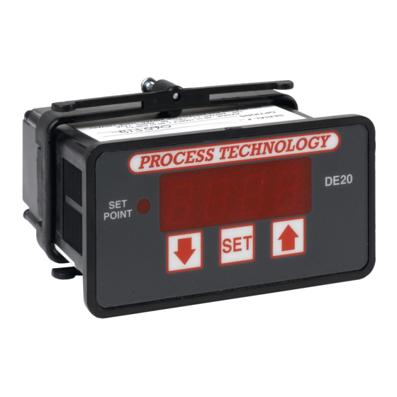
DE20 Instruction Manual
TABLE OF CONTENTS
DE20 Digital Temperature Control
Specifications....................................................................1
General Description.........................................................2
Installation Procedure.....................................................2
Overtemperature Protection...........................................3
Set Point & Features.........................................................4
Alarm Feature.....................................................................4
Error Conditions................................................................4
Error Messages.................................................................4
Power and Relay Wiring....................................................5
2 Wire RTD Sensor Calibration.......................................6
Resistance Signal Calibration.......................................7
3 Wire RTD Calibration..................................................7
Thermocouple Calibration.............................................8
Voltage Signal Calibration..............................................8
Current Input Calibration.................................................9
Frequency Signal Calibration.....................................10
7010 Lindsay Drive • Mentor, Ohio 44060 • Phone: 440-974-1300
USA/CN: 800-621-1998 • Fax: 440-974-9561 • www.process-technology.com
M-33-01-02 02/17/11
Configuration (Setup)....................................................10
Main Menu Summary.....................................................10
Sensor Type (U1).............................................................11
Signal Offset (U2)...........................................................11
Signal Filter Setting (U4)..................................................11
Set Point Dead Band (U5) .........................................12
Display Stabilizer (U8)...................................................12
Set Point Limit (L)..........................................................12
Heating or Cooling Switch (F2).....................................12
Alarm On/Off Switch (F3)..............................................13
Unit Display Enable (F4)..................................................13
Temperature Units Conversion (F5)............................13
Sensor DIP Switch Settings........................................13
Electrical Noise and Interference.................................13
Illustration of a Typical Heater Installation in a
Process Tank ...................................................................14
Advertisement
Table of Contents

Subscribe to Our Youtube Channel
Related Manuals for Process Technology DE20


Summary of Contents for Process Technology DE20
- Page 1 DE20 Instruction Manual TABLE OF CONTENTS DE20 Digital Temperature Control Specifications..............1 Configuration (Setup)............10 General Description............2 Main Menu Summary.............10 Installation Procedure.............2 Sensor Type (U1).............11 Overtemperature Protection...........3 Signal Offset (U2)............11 Set Point & Features............4 Signal Filter Setting (U4)..........11 Alarm Feature..............4 Set Point Dead Band (U5) .........12 Error Conditions..............4...
- Page 2 A more common source of DE20 Specifications interference occurs when the control is switching inductive loads such as contactor coils, solenoids or 2 wire- 1000 ohm RTD TCR (alpha), motors.
- Page 3 The temperature sensor (i.e. RTD or thermocouple) This setting may be set to a zero (0) or a one (1). When set to one (1), the DE20 will display either a “C” or an sends a signal to the DE20 controller. The DE20 com- “F”, separated by a decimal point.
- Page 4 “F5” setting Note: This does not apply to THERMOCOUPLES. You In addition to thermal protection, Process Technology Voltage Sensor - Number represents tenths of a volt (0.1 VDC)
- Page 5 “SET” key and the increase “ ” key A small “c” in the lower left-hand corner indicates the Using a small value for this setting will cause the DE20 control to respond more quickly to sudden changes simultaneously and holding them for approximately control is relying on default configuration values.
- Page 6 Power , Heating and Cooling Relay Wiring (rear view of controller) use the increase “ ”, decrease “ ” buttons to bring The DE20 control measures frequency and com- the particular setting into the view on the display. pares that measurement with a “standard” set of val- Press the “SET”...
- Page 7 20.0. Step 11: Turn OFF power to the control and remove The DE20 control measures the DC current and com- the power supply. Reinstall the voltage input and the pares that measurement with a “standard” set of val- Step 10: Press and hold the “SET”...
- Page 8 Step 5: CAREFULLY restore power to the controller, making sure that you do not come in contact with any Equipment needed: The DE20 can be equipped with an optional thermo- exposed voltage. Two precision resistors (tolerance +/- 0.1% couple sensor board (Item Number 5417). Installa- Step 6: Press the decrease “...
Need help?
Do you have a question about the DE20 and is the answer not in the manual?
Questions and answers