RollSeal RS-500 Series Troubleshooting Manual
Hide thumbs
Also See for RS-500 Series:
- Installation manual (68 pages) ,
- Installation and operation manual (57 pages) ,
- Installation manual (63 pages)

Related Manuals for RollSeal RS-500 Series


Summary of Contents for RollSeal RS-500 Series
-
Page 1: Troubleshooting Guide
RS-500/600 Doors Troubleshooting Guide RollSeal 1733 County Road 68 Bremen, Alabama 35033 256-287-7000 Part No 4801-5158 Rev 1-2017 Owners Manual RS 500/600 Series Doors... -
Page 2: Table Of Contents
Limited Warranty ..............................8 Introduction ................................9 How the SC-325 & SC-650 Controllers Communicate with the RollSeal RS-500/600 Door......10 SC-325 V1 Controller Layout ..........................11 SC-325 V2 Controller Layout ..........................12 ... -
Page 3: Warnings (Avertissements)
Warnings (Avertissements) Warning! Disconnect All Power Sources Before Installing This Equipment. Failure To Disconnect Power Source Can Result In Property Damage, Serious Injury Or Death! Warning! Dangerous Rotating Machinery! Keep Hands, Clothing, Etc. Clear When Operating! Do Not Operate Without All Guards And Covers In Place! Warning! All Wiring Should Be In Accordance with National Electrical Codes Or Other Local Codes. -
Page 4: Important Installation Instructions
Danger! Only Qualified Electrical Personnel Familiar With The Construction And Operation Of This Equipment And The Hazards Involved Should Install, Adjust, And/Or Service This Equipment. Read And Understand This Manual In Its Entirety Before Proceeding. Failure To Observe This Precaution Could Result In Severe Bodily Injury Or Death! Warning! Item 4501-6312 (Warning Moving Door Label) -
Page 5: Important Safety Instructions
IMPORTANT SAFETY INSTRUCTIONS Warning! To Reduce The Risk Of Severe Injury Or Death: 1. READ AND FOLLOW ALL INSTRUCTIONS! 2. Never let children operate or play with door controls. Keep the remote control (where provided) away from children. 3. Personnel should keep away from a door in motion and keep the moving door in sight until it is completely closed or opened. - Page 6 Avertissement ! Tout montage sur fil de fer doit être selon codes électriques nationaux ou autres indicatifs régionaux. Avertissement ! L'Installer est responsable pour conformer avec tout règlement pertinent, telles que règlement et règlement de prévention d'accident de montage sur fil de fer nationaux. Pl'attention articulaire doit être donnée pour les aires sectionnelles transversales de conducteurs, le choix d'elles fusées ou autre protection, et terre / prises de terre protecteur !
- Page 7 LES INSTRUCTIONS D'INSTALLATION IMPORTANTES AVERTISSEMENT! À réduire le risque de blessure sévère ou mort: 1. LU ET SUIVENT TOUTES INSTRUCTIONS D'INSTALLATION. 2. Ne liez pas l'opérateur de porte per la source de pouvoir jusqu'à instruit faire ainsi. 3. Localisez la station de commande: (a) en vue de la porte, (b) à un minimum la hauteur de 5 pieds ainsi petit enfants ne peuvent pas l'atteindre, et (c) loin de tous parties en mouvement de la porte.
-
Page 8: Limited Warranty
This warranty gives you specific legal rights and you may also have other rights that vary from area to area. Warrantor: RollSeal 1733 County Road 68 Bremen, Al 35055 256-287-7000 Page 8... -
Page 9: Introduction
Should Be Performed By A Qualified Electrician. The RollSeal SC-325 & SC-650 are Intelligent Controllers manufactured specifically for the RollSeal RS-500/600 Automatic Doors. The SC-325 & SC-650 Controllers will provide safe opening and closing of the door by using a number of internal safety devices plus those features provided in the components of the RS-500/600 Door. -
Page 10: How The Sc-325 & Sc-650 Controllers Communicate With The Rollseal Rs-500/600 Door
RollSeal RS-500/600 Door. Inside the upper right housing of the RollSeal RS-500/600 Door is an Encoder that sends electrical pulses to the SC-325 & SC-650 Controllers. When the door is moving, the Controller is in normal operating mode. (See Section 20 or Manual #4801-5156 for wiring diagram of the Encoder). -
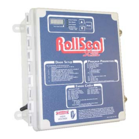
Page 11: Sc-325 V1 Controller Layout
SC-325 V1 Controller Layout WARNING! Ensure The Drive AC Selection Jumper AND PCB 154 AC Selection Switch Are Set Accordingly BEFORE Power Is Applied To The Controller. Part No 4801-5158 Rev 1-2017 RS500/600 Series Doors Page 11... -
Page 12: Sc-325 V2 Controller Layout
SC-325 V2 Controller Layout WARNING! Ensure The Drive AC Selection Jumper AND PCB 154 AC Selection Switch Are Set Accordingly BEFORE Power Is Applied To The Controller. Page 12 RS500/600 Series Doors Part No 4801-5158 Rev 1-2017... -
Page 13: Sc-650 V1/V2 Controller Layout
SC-650 V1/V2 Controller Layout WARNING! Ensure The Drive AC Selection Jumper AND PCB 154 AC Selection Switch Are Set Accordingly BEFORE Power Is Applied To The Controller. Part No 4801-5158 Rev 1-2017 RS500/600 Series Doors Page 13... -
Page 14: Troubleshooting Flowchart
Troubleshooting Flowchart Looking at the SC-325 or SC-650, What is shown on Display? Three Dashes Unknown Position indication. (---) See Section 9 Press “Open” button to reset Alternates between Three Dashes and a the Actual Position Numerical (178) Actual Position Check Egress Strap to ensure that the strap is in the correct Reset Egress Strap. - Page 15 Troubleshooting Flowchart (cont.) Will any item When the door run or door panel does the While Obstruction LED From in Jog Mode? between door Obstruction Opened lit on the Page 14 See Section Safety LED come Display? Beams? While Closing Adjust the Leading Edge Switch.
-
Page 16: Unknown Position Indication
Unknown Position Indication Unknown Position Indication There are occasions when the Controller may not know the exact position of the door. For example, when returning from the Jog Mode. In these cases the Display Actual Position - - - Indicator will display a series of three bars as shown to Open Speed the right. -
Page 17: Error Codes
11 Error Codes Mechanical Errors Panel Problem Code Condition Movement Area Possible Solutions Opening, Home Switch Try to activate door normally (open), should fix Home Switch itself. Use Jog Mode to lower door panel below Home Switch. See Section 13 Manually release Brake and pull panel below Home Switch. - Page 18 Feedback Errors (Cont.) Panel Code Condition Movement Problem Area Possible Solutions EOF1 Opening, None Brake Encoder Check Brake Relay on PCB154 Control Fault Board. See Section 18 Brake Rectifier Check Brake Rectifier in motor. See Section 18 Brake Assembly Make sure Brake is not adjusted too tight or that the brake assembly is defective.
- Page 19 Feedback Errors (Cont.) Panel Code Condition Movement Problem Area Possible Solutions ECF2 Closing, Drive Direction Fault Reverse two phases to the motor Down Encoder Signal Wires (A, B) reversed. See Diagram 11C Disengage Brake AC & DC Harness Part No 4801-5158 Rev 1-2017 RS500/600 Series Doors Page 19...
- Page 20 AC & DC Harness Page 20 RS500/600 Series Doors Part No 4801-5158 Rev 1-2017...
-
Page 21: Adjustment Of Brake
12 Adjustment of Brake After extended operation of the brake lever, the brake may become worn. As the brake wears, some adjustment to the brake is required. Lettered diagrams below correspond to lettered instructions. Follow instructions to adjust brake: Tighten spider nut (C) snuggly against Close door curtain to fully lowered position. -
Page 22: Jog Mode
13 Jog Mode JOG Mode The Jog Mode will permit an operator to manually control the position of the door with the Up ( ) and Down ( ) arrow buttons. To enter the Jog Mode, press both the Up ( ) and Actual Position Down ( ) arrows at the same time for at least 5 seconds. -
Page 23: Switch Testing
15 Switch Testing With the Sequential Switch and the Direction Switch terminal blocks removed all input signals are disabled. Any input signal to make the door operate will come from this test. For a quick overview there are two types of operator inputs that can be connected to the SC-325 &... -
Page 24: Sequential Switch Input Test And Manual (Single) Switch Input Test
These features would be useful if an operator wanted to “lock” the door in a particular position with the use of external switches connected in parallel with the directional switch. For safety reasons, these directional buttons have a priority built into the SC-325& SC-650 Controllers in case one or more of the buttons are pressed at the same time. -
Page 25: Direction Swx Test
16 Direction SWX Test To perform all tests below you must have a short piece of wire. This wire should be approximately 5 inches long and 16AWG – 18AWG in size. Each test performed will be located in the same area of the PCB 154 of the Door Assembly as show below. -
Page 26: Close Direction Test
16.2 Close Direction Test Momentarily place the jumper on the pins of Out to Close. The door should close to its full close position. Care should be taken that this wire only touches these two points. 16.3 Stop Position Test 1. -
Page 27: Adjusting The Home, Safety, And Leading Edge Switches
17 Adjusting the Home, Safety, and Leading Edge Switches At some point it may be necessary to adjust one of the three switches located within the horizontal member mechanism of the door. You can these access switches by removing the cover or through the Access Door (See Diagram 4A). -
Page 28: 2005 And Earlier Switch Adjustment
The installation of the Leading Edge Switch changed in January 2006. The switch setting will depend on the year model of the door. Notice the difference in the two brackets used and how the switch is mounted to it. 2005 and Earlier 2006 and Later 17.1 2005 and Earlier Switch Adjustment Adjust the Leading Edge Switch at 180 degrees from its mounted position. -
Page 29: 2006 And Later Switch Adjustment
17.2 2006 and Later Switch Adjustment Adjust the Leading Edge Switch at 170 degrees from its mounted position. After adjusting the Leading Edge Switch make sure it is positioned downward against the door panel. Part No 4801-5158 Rev 1-2017 RS500/600 Series Doors Page 29... -
Page 30: Brake Relay Test
18 Brake Relay Test The gear motors on the RS-500/600 Series Doors have a Brake Rectifier which will activate the brake in the gear motor to stop the unit when not in use. There is a relay (acting as a switch) on the PCB 154 board in the Door Assembly of the Controller that will turn this brake on and off. - Page 31 Brake Rectifier Jumper Part No 4801-5158 Rev 1-2017 RS500/600 Series Doors Page 31...
-
Page 32: Brake Rectifier
18.2 Brake Rectifier The Brake Rectifier is a device in the door gear motor junction box. The Brake Rectifier is supplied voltage from the Controller and is activated by a Brake Relay on the PCB 154 Controller Board. When the Controller supply voltage is 115 VAC and a 3017-5052 A-100 Brake Rectifier is installed inside the door gear motor junction box, the output Brake voltage should be approximately 100 VDC loaded and approximately 110 VDC unloaded. - Page 33 Warning! Dangerous High Voltages! Allow Approximately 5 Minutes For The Controller To Power-Down Before Changing Switch Settings, Jumper Placement, Or Wiring. Warning! Use The Correct RS Door Brake Rectifier For The Specific Required Voltage! Using A 230 VAC Brake Rectifier With A 115 VAC Power Supply Can Result In Improper Door Operation Due To The Mechanical Brake Not Releasing Properly.
-
Page 34: Emergency Egress (Optional Feature)
Buckle. This view shows the Cam Buckle as see from the front of the door. RollSeal, Inc. • 1733 County Road 68 • Bremen, Alabama 35033 • 256-287-7000 Page 34 RS500/600 Series Doors Part No 4801-5158 Rev 1-2017... -
Page 35: Egress Bracket Removal
19.2 Egress Bracket Removal 1. Close the door. If necessary, the door can be closed using “Jog” mode. See your owner’s manual for more information. Warning! Disconnect All Power Sources Before Installing This Equipment. Failure To Disconnect Power Source Can Result In Property Damage, Serious Injury Or Death! 2. -
Page 36: Rollseal Automatic Door Wiring Diagram
20 RollSeal Automatic Door Wiring Diagram See Page 37 See Page 37 W A R N I N G ! Head Unit Must Be Properly Grounded. Page 36 RS500/600 Series Doors Part No 4801-5158 Rev 1-2017... -
Page 37: Rollseal Smart Controller Wiring Diagram
21 RollSeal Smart Controller Wiring Diagram See Page 36 See Page 36 Part No 4801-5158 Rev 1-2017 RS500/600 Series Doors Page 37... -
Page 38: Warning Light Control Wiring
21.1 Warning Light Control Wiring 21.2 Interlocking Two Automatic Doors Page 38 RS500/600 Series Doors Part No 4801-5158 Rev 1-2017... -
Page 39: Rollseal Cms (Condensation Management System) Wiring Diagram
22 RollSeal CMS (Condensation Management System) Wiring Diagram 23 Optional Accessory Wiring 23.1 Falcon XL and EX Motion Sensors Part No 4801-5158 Rev 1-2017 RS500/600 Series Doors Page 39... -
Page 40: Falcon Is40 Infrared And Microwave Sensor
23.2 Falcon IS40 Infrared and Microwave Sensor 23.3 IRIS Infrared and Microwave Sensor Page 40 RS500/600 Series Doors Part No 4801-5158 Rev 1-2017... -
Page 41: Matrix2 Loop Sensor
23.4 Matrix2 Loop Sensor Part No 4801-5158 Rev 1-2017 RS500/600 Series Doors Page 41... -
Page 42: Switches And Remote Receiver
24 Switches and Remote Receiver 24.1 Controller and Brother Motor Page 42 RS500/600 Series Doors Part No 4801-5158 Rev 1-2017... - Page 43 Part No 4801-5158 Rev 1-2017 RS500/600 Series Doors Page 43...
- Page 44 Page 44 RS500/600 Series Doors Part No 4801-5158 Rev 1-2017...
Need help?
Do you have a question about the RS-500 Series and is the answer not in the manual?
Questions and answers