Table of Contents
Advertisement
Quick Links
ConsoliDator
Multi-Channel Controller
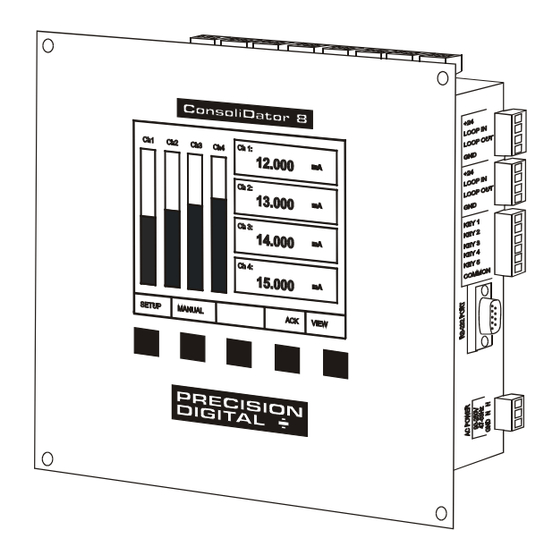
ConsoliDator 8
•
Eight 4-20 mA Inputs
•
Eight 24 VDC @ 20 mA
•
Two 4-20 mA Outputs
•
Nine Form C 10 A Relays
•
Four Pulse Inputs
•
Four Digital Inputs
•
Panel or wall mount
•
Sum and Difference
Functions
PRECISION DIGITAL CORPORATION
19 Strathmore Road • Natick MA 01760 USA
Tel (800) 343-1001 • Fax (508) 655-8990
Instruction Manual
ConsoliDator 4
•
•
•
Features and Highlights
•
•
•
•
•
New PC
Software
Included!
Four 4-20 mA Inputs
Four 24 VDC @ 20 mA
Four 4-20 mA Outputs
Powered from AC or DC
32-Point Linearization
®
RS-232 Modbus
RTU
Square Root Function
FREE Programming &
data logging software
www.predig.com
®
Advertisement
Table of Contents

Related Manuals for PRECISION DIGITAL ConsoliDator 4


Summary of Contents for PRECISION DIGITAL ConsoliDator 4
- Page 1 ® ConsoliDator Multi-Channel Controller Instruction Manual New PC Software Included! ConsoliDator 8 ConsoliDator 4 • • Eight 4-20 mA Inputs Four 4-20 mA Inputs • • Eight 24 VDC @ 20 mA Four 24 VDC @ 20 mA • •...
- Page 2 All trademarks mentioned in this document are the property of their respective owners. Copyright © 2003-2005 Precision Digital Corporation This document contains ratings and requirements necessary for proper installation. Distribution of modified versions is strictly prohibited. Any text, chart, diagram, or table...
-
Page 3: Introduction
ConsoliDator Multi-Channel Controller Instruction Manual INTRODUCTION The ConsoliDator is an easy to use multiple-channel controller. It accepts 4-20 mA inputs, flow meter pulse inputs, and digital inputs. It is equipped with multiple relays, which all have user-definable actions, 4-20 mA outputs, and Modbus protocol communication capabilities. ORDERING INFORMATION ConsoliDator Controllers 4-20... -
Page 4: Table Of Contents
ConsoliDator Multi-Channel Controller Instruction Manual TABLE OF CONTENTS INTRODUCTION ----------------------------------------------------------------------- 3 ORDERING INFORMATION -------------------------------------------------------- 3 TABLE OF CONTENTS-------------------------------------------------------------- 4 SPECIFICATIONS--------------------------------------------------------------------- 7 General------------------------------------------------------------------------------------------- 7 4-20 mA Analog Inputs --------------------------------------------------------------------- 8 Flow Meter Pulse Inputs-------------------------------------------------------------------- 8 Digital Inputs ----------------------------------------------------------------------------------- 8 Relays -------------------------------------------------------------------------------------------- 9 4-20 mA Transmitter Outputs----------------------------------------------------------- 10 ®... - Page 5 CONSOLIDATOR MONITOR SOFTWARE ----------------------------------- 51 Connecting to PC--------------------------------------------------------------------------- 51 Installing Software ------------------------------------------------------------------------- 51 Using ConsoliDator Monitor Software----------------------------------------------- 51 Data Logging ------------------------------------------------------------------------------ 52 Programming Through Software------------------------------------------------------ 52 OVERALL DIMENSIONS ---------------------------------------------------------- 53 TROUBLESHOOTING TIPS ------------------------------------------------------ 54 OTHER PRECISION DIGITAL PRODUCTS ---------------------------------- 55...
- Page 6 ConsoliDator Multi-Channel Controller Instruction Manual Table of Figures Figure 1. Wall Mount Dimensions (PD980 & PD940) ........12 Figure 2. Panel Mount Dimensions (PD981 & PD941) ........13 Figure 3. Power Connections ................14 Figure 4. Transmitter Powered by Ext. Supply or Self-Powered ....15 Figure 5.
-
Page 7: Specifications
ConsoliDator Multi-Channel Controller Instruction Manual SPECIFICATIONS Except where noted all specifications apply to operation at +25°C (77°F.) General DISPLAY Graphical: 4.75" x 3.5" (121 mm x 89 mm) LCD with backlight 320 X 240 pixels; Bargraph: Twenty divisions; Numerical: ±999999 or 99’... -
Page 8: 4-20 Ma Analog Inputs
ConsoliDator Multi-Channel Controller Instruction Manual 4-20 mA Analog Inputs INPUT 4-20 mA; minimum span of 1 mA ACCURACY ±0.03% of span ±1 count TEMPERATURE DRIFT 50 PPM/°C from 0 to 50°C ambient INPUT FUNCTION Linear, Square Root, Programmable Exponent, Multi-Point (up to 32), or Fixed Value MATH FUNCTION Sum or difference of 2 or more channels. -
Page 9: Relays
ConsoliDator Multi-Channel Controller Instruction Manual Relays RATING SPDT (form C); rated 10 A @ 120/240 VAC or 5 A @ 28 VDC resistive load; 1/3 HP @ 120/240 VAC for inductive loads. Minimum load: 50 mA for AC, 10 mA @ 5 VDC ISOLATION 1500 VAC between coil and contacts DEADBAND... -
Page 10: 4-20 Ma Transmitter Outputs
® ConsoliDator Software SYSTEM Windows® 95/98/ME/NT4/2000/XP REQUIREMENTS COMPATABILITY Separate versions for ConsoliDator 4 and ConsoliDator 8. COMMUNICATION RS-232 using null-modem serial cable. LOGGING Programmable between 1 sec. and 10 min. REPORTS LOGGING REPORT Log to comma separated value (.csv) file compatible with spreadsheet applications such as Microsoft®... -
Page 11: Safety Information
ConsoliDator Multi-Channel Controller Instruction Manual SAFETY INFORMATION CAUTION: Read complete WARNING: Risk of instructions prior to installation electric shock. and operation of the controller. WARNING Hazardous voltages present. Installation and service should be performed only by trained service personnel. -
Page 12: Installation
ConsoliDator Multi-Channel Controller Instruction Manual INSTALLATION Unpacking Remove the instrument from its box. Inspect the packaging and contents for damage. Report any damages to the carrier. If any part is missing or the controller malfunctions, please contact your supplier or the factory for assistance. Wall Mounting (For PD980 &... -
Page 13: Panel Mounting
ConsoliDator Multi-Channel Controller Instruction Manual Panel Mounting (For PD981 & PD941 Models) • Obtain four #8 (M4) screws and nuts. • Obtain four washers with at least 5/16" (8 mm) O.D. If the device will be subjected to vibration, lock washers are necessary. •... -
Page 14: Connections
ConsoliDator Multi-Channel Controller Instruction Manual Connections Connections are made to removable screw terminal connectors and a DB9 male serial connector. They are located around the sides of the controller. Use copper wire with 60°C or 60/75°C insulation for all line voltage connections. Observe all safety regulations. Electrical wiring should be performed in accordance with all applicable national, state, and local codes to prevent damage to the instrument and ensure personnel safety. -
Page 15: Input Signal Connections
ConsoliDator Multi-Channel Controller Instruction Manual Input Signal Connections Input signal connections are made to terminal connectors, which are labeled individually on the controller. 4-20 mA Analog Input Connections Analog 4-20 Input connections are made to three-terminal connectors. The following figures show examples for typical applications. -
Page 16: Flow Meter Pulse Input Connections
ConsoliDator Multi-Channel Controller Instruction Manual Flow Meter Pulse Input Connections Flow Meter Pulse Inputs are wired to two-terminal connectors. A square waveform is used in the illustration, but the input is capable of reading many other types of signals within the voltage and frequency ranges specified. -
Page 17: Analog Output Connections
ConsoliDator Multi-Channel Controller Instruction Manual Analog Output Connections The following figures show examples for 4-20 mA transmitter output connections. Terminal connectors are labeled individually on the side of the case. In order to obtain isolation from analog inputs, outputs must be powered from an external supply as shown in Figure 11. ANALOG OUTPUT Remote Display, Chart Recorder, etc. -
Page 18: Relay Connections
Figure 14. Low Voltage DC Loads Protection RC Networks Available from Precision Digital RC networks are available from Precision Digital and should be applied to each relay contact switching an inductive load. Part number: PDX6901. -
Page 19: Serial Communication Connections
RS-485, but only one ConsoliDator with RS-232. Data Converters Available from Precision Digital Serial converters available from Precision Digital support a wide range of devices. Please reference part number PDA7485 when requesting information. External Keypad Connections Normally open pushbuttons may be wired to the six-terminal external keypad connector for use when the front panel of the controller is not accessible. -
Page 20: Navigating And Editing
ConsoliDator Multi-Channel Controller Instruction Manual NAVIGATING AND EDITING The device displays various screens throughout programming and operation. Functions are programmed within their respective menu screens in many cases accompanied by user prompts. Soft-Keys and Buttons The unit is equipped with five buttons located below the display. The function of each button corresponds to its soft-key, which appears at the bottom of the screen. -
Page 21: Setup And Programming
ConsoliDator Multi-Channel Controller Instruction Manual SETUP AND PROGRAMMING There is no need to recalibrate the instrument when first received from the factory. The device is factory calibrated prior to shipment, for all input types. The calibration equipment is certified to NIST standards. -
Page 22: Main Setup Menu
ConsoliDator Multi-Channel Controller Instruction Manual Inputs Outputs Channel #1 Alarm Relay #1 Channel #2 Alarm Relay #2 Main Setup Menu Channel #3 Alarm Relay #3 Channel #4 Alarm Relay #4 Channel #5 Alarm Relay #5 The main setup menu is the Channel #6 Alarm Relay #6 Channel #7... -
Page 23: Contrast
ConsoliDator Multi-Channel Controller Instruction Manual Contrast Select Adjust Contrast and press the ADJ key continuously to darken the display contrast. After the darkest possible setting is reached, the ADJ key returns the display to its lightest setting. Backlight Selecting [YES] under Save BL automatically turns the backlight off if no buttons are pressed for five minutes. -
Page 24: Configuring 4-20 Ma Inputs
ConsoliDator Multi-Channel Controller Instruction Manual Configuring 4-20 mA Inputs Analog Input: 1 Input Type: 4-20 mA Transmitter The Analog Input setup screen is used Function: NONE - Linear to configure the 4-20 mA analog inputs. Channel ID: Analog 1 Each channel has a separate menu. All 4-20 mA inputs can be configured using Configure Function Parameters the information provided in this section. -
Page 25: Input Scaling & Math Functions
ConsoliDator Multi-Channel Controller Instruction Manual Input Scaling & Math Functions The ConsoliDator is capable of various functions for scaling the 4-20 mA inputs. Linear Square Root, Programmable Exponent, and Integration are two-point scaling functions. Multi-Point is capable of handling up to 32 scaling points and requires that the ConsoliDator Monitor Software be used to enter these points. -
Page 26: Square Root
ConsoliDator Multi-Channel Controller Instruction Manual Square Root Square root mode refers to 2-point scaling with square root extraction typically used to linearize the signal from a differential pressure transmitter and display the flow rate in engineering units. The graph in Figure 18 shows the display response based on example scaling parameters. -
Page 27: Exponent
ConsoliDator Multi-Channel Controller Instruction Manual Exponent Exponent mode refers to 2-point scaling with programmable exponent (programmable root) extraction typically used in open-channel flow applications with weirs and flumes to linearize the signal from a level transmitter and display the flow rate in engineering units. -
Page 28: Integration Mode
ConsoliDator Multi-Channel Controller Instruction Manual Integration Mode Integration mode is able to totalize from any 4-20 mA channel over a time base of second, minute, hour, or day. During operation, the channel’s display screen shows bargraph total, numeric total, and numeric rate. To begin setup, select from the following under Function options [Integration: SEC], [Integration: MIN], [Integration: HOUR], or [Integration: DAY]. -
Page 29: Multi-Point Linearization
ConsoliDator Multi-Channel Controller Instruction Manual Multi-Point Linearization Multi-Point Linearization must be configured using a PC and supplied ConsoliDator Monitor Software. After communication has been established between PC and ConsoliDator, select System Settings from the software’s menu bar. Next, select a channel to set up from the Analog Input Channels drop-down menu and press Edit Channel. -
Page 30: Setting Flow Meter Pulse Inputs
ConsoliDator Multi-Channel Controller Instruction Manual Setting Flow Meter Pulse Inputs Flow Meter: 1 State: The Flow Meter menu is used to configure a flow meter pulse input. All Channel ID: Flow: 1 ENABLED pulse input screens offer the same K Factor: 1000.00 pls / GAL options as described in this section. -
Page 31: Programming Relays
ConsoliDator Multi-Channel Controller Instruction Manual Programming Relays Each relay has an Alarm Setup menu used to program its functions. Functions are programmed individually for each relay except in the case of Lead-Lag mode. Each relay has the same available functions. All relays may be manually overridden. Before the relays are set up, verify that the inputs have been configured. -
Page 32: Multi-Channel High Or Low Alarm Modes
ConsoliDator Multi-Channel Controller Instruction Manual Multi-Channel High or Low Alarm Modes Alarm Setup: 1 Multi-Channel High or Low modes are used as an alarm triggered by a Alarm Mode: HIGH: Multi-Chan set point common to the linked channels. High Value: 160.0 GAL Select [HIGH: Multi-Chan] from Low Value:... -
Page 33: High Or Low Pulse Alarm Modes
ConsoliDator Multi-Channel Controller Instruction Manual High or Low Pulse Alarm Alarm Setup: 1 Modes Alarm Mode: HIGH: Pulse Mode Pulse Modes are used to generate Channel: [1] Analog: 1 an on/off continuous pulsing signal. High Value: 16.00 mA Select [HIGH: Pulse Mode] from Low Value: 8.00 mA Alarm Mode options to continuously... -
Page 34: Trigger Alarm Mode
ConsoliDator Multi-Channel Controller Instruction Manual Alarm Setup: 1 Alarm Mode: Trigger Channel: [A] Flow: 1 Trigger Alarm Mode Set Point: 10.00 GAL Pl Width: Select Trigger mode to pulse the relay once each time the total from a flow meter pulse input channel is incremented by a certain value. -
Page 35: Plunger Lift By Differential Pressure Mode
ConsoliDator Multi-Channel Controller Instruction Manual Alarm Setup: 1 Alarm Mode: PLUNGER LIFT: DP Tubing Ch: [A] Flow: 1 Plunger Lift by Differential Casing Ch: [2] Analog: 2 Pressure Mode Switch Ch: [1] Reed SW: 1 Select [PLUNGER LIFT: DP] from Set Point: 100.00 GPM Alarm Mode options to operate a... -
Page 36: Lead-Lag Modes (Pump Alternation Control)
ConsoliDator Multi-Channel Controller Instruction Manual Lead-Lag Modes (Pump Alternation Control) Alarm Setup: 1 Lead-Lag modes are used to Alarm Mode: LEAD-LAG: HIGH operate up to 9 relays in sequence. Channel: TANK 1 This mode is commonly used for High Value: 160.0 GAL pump alternation control. - Page 37 ConsoliDator Multi-Channel Controller Instruction Manual Lead-Lag Override: 1 Lead-Lag Override Function Over Type: Override 1 & 2 ON Set Pt. #1: 170.0 GAL Lead-Lag mode supports an override function, which allows up to Set Pt. #2: 180.0 GAL five linked relays to turn on if programmed points are reached.
-
Page 38: Linear Pulse Width Modulation Mode
ConsoliDator Multi-Channel Controller Instruction Manual Linear Pulse Width Modulation Mode Alarm Setup: 1 Linear PWM Mode is used to create Alarm Mode: PWM: Linear an on/off pulse signal with a modulated duty cycle. In this mode Channel: [A] Flow: 1 the percentage of the relay cycle in 100% Value: 16.00 GPM... -
Page 39: Proportional Plus Integral Pulse Width Modulation Mode
ConsoliDator Multi-Channel Controller Instruction Manual Alarm Setup: 1 Proportional Plus Integral Pulse Width Modulation Mode Alarm Mode: PWM: PI Control Feedbk Ch: [A] Flow: 1 PWM PI Control Mode is used to Set Point: 12.00 GPM create an on/off pulse signal with a Prop. -
Page 40: Setting 4-20 Ma Outputs
ConsoliDator Multi-Channel Controller Instruction Manual Setting 4-20 mA Outputs The Analog Output menu is used to configure the 4-20 mA outputs. Each output has a separate screen. All 4-20 mA outputs can be configured using the information provided in this section. Analog Output: 1 Linear Scaling of 4-20 mA Output... -
Page 41: Operation
ConsoliDator Multi-Channel Controller Instruction Manual OPERATION Viewing Screens The instrument displays various screens with bargraphs, numerical values, and relay status throughout operation. There are two basic modes of operation: Automatic, which allows the controller to function based on it’s programmed settings; and Manual mode, which disables all automatic output functions. - Page 42 ConsoliDator Multi-Channel Controller Instruction Manual Multiple Channel Operation Ch 1: Screen 12.000 To the right is an example of a multiple channel operation screen Ch 2: for a four input application. The 13.000 screen reflects all of the inputs that were detected or enabled during Ch 3: setup.
- Page 43 ConsoliDator Multi-Channel Controller Instruction Manual 500 GAL Single Flow Meter Pulse Input Flow: 1 Operation Screen 300.0 For each flow meter pulse input channel, there is a detailed individual channel operation screen, which shows a bargraph with relay Rate: 220.00 GPH set points, numerical values for rate Rly: Low:...
- Page 44 ConsoliDator Multi-Channel Controller Instruction Manual Analog Sensor Inputs: Analog Input Numeric Screen Tank 1 Tank 2 To the right is an example of an 50.000 ft 40.000 ft analog numeric summary screen for 16.00 mA 12.00 mA an eight input application. It shows Tank 3 Tank 4 30.000 ft...
-
Page 45: Manual And Simulation Modes
ConsoliDator Multi-Channel Controller Instruction Manual Manual and Simulation Modes When manual mode is entered, all outputs are suspended or frozen in their current state until they are changed manually, although totalization continues while in Manual mode. For example: Relay #1 is programmed to activate a pump based on the level of Channel #1. -
Page 46: Modbus ® Serial Communication
PID Output Value Floating Point Output Type Byte Input Ch. Byte PID KP Integer PID KI Integer PID KD Integer PID Cycle Time Integer PID I Band Integer PID Direction Integer *Channels 3-4 only apply to ConsoliDator 4 (PD940 & PD941) models. - Page 47 ConsoliDator Multi-Channel Controller Instruction Manual Table 2. Analog Input Channels Register Addresses Address (offset from 40000) Description Data Type Ch. 1 Ch. 2 Ch. 3 Ch. 4 Ch. 5* Ch. 6* Ch. 7* Ch. 8* Engineering Value Floating Point Max. Graph Value Floating Point Min.
- Page 48 ConsoliDator Multi-Channel Controller Instruction Manual Table 3. Flow Meter Pulse Input Channels Register Addresses Address (offset from 40000) Description Data Type Ch. 1 Ch. 2 Ch. 3 Ch. 4 Flow Meter Rate Floating Point Flow Meter Total Floating Point K Factor Floating Point Maximum Graph Value Floating Point...
- Page 49 ConsoliDator Multi-Channel Controller Instruction Manual Table 5. Relay Channels Register Addresses Address (offset from 40000) Description Data Type Rly. 1 Rly. 2 Rly. 3 Rly. 4 Rly. 5 Rly. 6 Rly. 7 Rly. 8 Rly. 9 Alarm High Set point Floating Pt. Alarm Low Set Point Floating Pt.
- Page 50 ConsoliDator Multi-Channel Controller Instruction Manual Table 6. Analog Inputs, Flow meter, and Relay State Summary Address (offset from 40000) Description Data Type Analog Channel #1 Engineering Value Floating Point (Rate value during integration mode.) Analog Channel #2 Engineering Value Floating Point (Rate value during integration mode.) Analog Channel #3 Engineering Value Floating Point...
-
Page 51: Consolidator Monitor Software
ConsoliDator Multi-Channel Controller Instruction Manual CONSOLIDATOR MONITOR SOFTWARE Each ConsoliDator is shipped with PC software on CD-ROM, which supports monitoring, data logging and controller setup/programming. You may also download this software from the web at www.predig.com. There are separate versions of the software for 4-channel and 8-channel models. -
Page 52: Data Logging
ConsoliDator Multi-Channel Controller Instruction Manual Data Logging The software supports logging input readings to a comma separated value file (*.csv) compatible with spreadsheet applications. Log settings appear in the lower left of the screen. First, specify a time interval from the Log Rate options. Note that small intervals will result in a large file size. -
Page 53: Overall Dimensions
ConsoliDator Multi-Channel Controller Instruction Manual OVERALL DIMENSIONS 8.75" (222mm) 3.0" (76mm) 8.0" (203mm) Figure 22. PD980 & PD940 Overall Dimensions 9.36" (238mm) 8.66" (220mm) 7.16" (182mm) 3.10" (79mm) 7.86" (200mm) Figure 23. PD981 & PD941 Overall Dimensions... -
Page 54: Troubleshooting Tips
ConsoliDator Multi-Channel Controller Instruction Manual TROUBLESHOOTING TIPS Symptom Check/Action Contrast is too light: Adjust contrast in main setup menu. Ambient temperature is below 0°C and affects LCD visibility: Adjust contrast to compensate. No display, or only backlight is High levels of radiated interference are present. visible, but outputs still function Steps must be taken to shield controller from normally. -
Page 55: Other Precision Digital Products
ConsoliDator Multi-Channel Controller Instruction Manual OTHER PRECISION DIGITAL PRODUCTS Model Description ® PD118 MINIMUX 8 Point Scanner ® PD141AFO VIGILANTE four Point Annunciator with First-Out PD602 Dart Low-Cost 1/8 DIN Process Meter PD644 Javelin D Volt Meter 0-300 VDC PD650 2.3”... - Page 56 How to Contact Precision Digital For Technical Support please call: (800) 610-5239 (508) 655-7300 fax: (508) 655-8990 e-mail: support@predig.com For Sales Support or to place an order please call: (800) 343-1001 (508) 655-7300 fax: (508) 655-8990 e-mail: sales@predig.com For an online version of this Instruction Manual please visit www.predig.com...
Need help?
Do you have a question about the ConsoliDator 4 and is the answer not in the manual?
Questions and answers