
Related Manuals for Extech Instruments UM200


Summary of Contents for Extech Instruments UM200
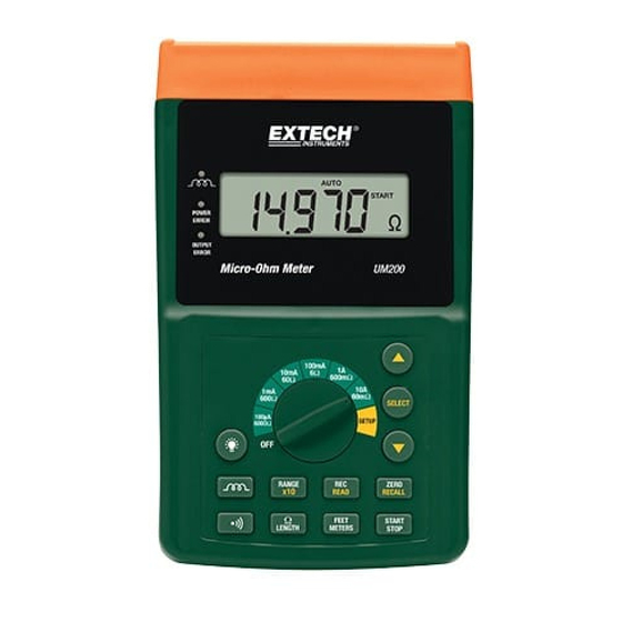
- Page 1 User Manual Micro-Ohmmeter Model UM200 Additional User Manual Translations available at www.extech.com ...
- Page 2 Introduction Thank you for selecting the Extech Model UM200. This device is shipped fully tested and calibrated and, with proper use, will provide years of reliable service. This device is shipped fully tested and calibrated and, with proper use, will provide years of reliable service. Please visit our website (www.extech.com) to check for the latest version and translations of this User Manual, Product...
-
Page 3: Meter Description
In the READ mode, users can recall data stored by pressing the ▲ or ▼ button. FEET / METERS button: In cable length mode, press the FEET / METERS button to select units of Meter (M) or Feet (FT). UM200-en-GB_V1.5 2/17... - Page 4 17. Ω / LENGTH button: Press Ω / LENGTH button to select measurement mode or length mode. Press Ω / LENGTH button for over 2 seconds to store the present value of resistance as the resistance per foot or meter. UM200-en-GB_V1.5 2/17...
-
Page 5: Rear Panel
P1 Alligator Clip Terminal or 4-wire Test Leads Terminal. P2 Alligator Clip Terminal or 4-wire Test Leads Terminal. C2 Alligator Clip Terminal or 4-wire Test Leads Terminal. - Kelvin Clip Terminal. +Kelvin Clip Terminal. POWER for the input of AC adaptor. UM200-en-GB_V1.5 2/17... -
Page 6: Operation
Place the rotary switch in any range position to charge the battery. Warning: Do not measure any resistance (object) with electrical potential (voltage). The electrical potential (voltage) could cause damage to the ohmmeter. 4 Wire Connection Methods Kelvin Clips UM200-en-GB_V1.5 2/17... - Page 7 RANGE button. Refer to the specifications for a list of the sub- ranges. The OL symbol will be shown in LCD if the value of resistance is out of sub-range. The resolution remains the same for the three sub-ranges. In the manual range, the AUTO symbol will disappear. UM200-en-GB_V1.5 2/17...
-
Page 8: Alarm Function
Ω/LENGTH button for over 2 seconds again. Disconnect the sample cable and connect the Kelvin clips to the cable to be measured. The LCD will display the length of the cable. If “OL” appears in the display, select a higher range and press START. UM200-en-GB_V1.5 2/17... - Page 9 NOTE: The memory capacity is 3000 data records. When 3000 records are exceeded, there will be a long beeping sound and no further data can be recorded.. Backlight Press the button to turn the backlight on or off. UM200-en-GB_V1.5 2/17...
-
Page 10: Battery Charging
Servicing not covered in this manual should only be performed by qualified personnel. Repairs should only be performed by qualified personnel. Periodically wipe the case and cable with a damp cloth and detergent; do not use abrasives or solvents. UM200-en-GB_V1.5 2/17... -
Page 11: Specifications
1μΩ ±(0.25%±25μΩ) 4.00mΩ to 600.00mΩ 10μΩ ±(0.25%±250μΩ) 100 mA 0.0400Ω to 6.0000Ω 100μΩ ±(0.25%±2.5mΩ) 10 mA 0.400Ω to 60.000Ω 1mΩ ±(0.25%±25mΩ) 1 mA 4.00Ω to 600.00Ω 10mΩ ±(0.25%±250mΩ) 100μA 0.0400kΩ to 6.0000kΩ 100mΩ ±(0.75%±3Ω) Copyright © 2013‐2017 FLIR Systems, Inc. All rights reserved including the right of reproduction in whole or in part in any form ISO‐9001 Certified www.extech.com UM200-en-GB_V1.5 2/17...
Need help?
Do you have a question about the UM200 and is the answer not in the manual?
Questions and answers