Extech Instruments MA440 User Manual
400a ac clamp meter dmm
Hide thumbs
Also See for MA440:
- User manual (16 pages) ,
- User manual (15 pages) ,
- User manual (23 pages)

Related Manuals for Extech Instruments MA440


Summary of Contents for Extech Instruments MA440
- Page 1 USER MANUAL Model MA440 400A AC Clamp Meter DMM Model MA443 True RMS 400 AC Clamp Meter DMM Model MA445 True RMS 400A AC/DC Clamp Meter DMM ...
- Page 2 Introduction Thank you for selecting the Extech EX44x Series 400A Clamp Meter. The MA440 is a 400A AC Clamp meter with a total of 9 functions. The MA443 is a 400A True RMS AC Clamp meter that offers 10 functions including TRMS AC measurements and Type K Thermocouple The MA445 is a 400A AC/DC True RMS Clamp meter with 11 functions including DC Current, TRMS AC measurements, and Type K Thermocouple. The MA44x series are hand‐held, 4000 count clamp meters. This meter series measures AC/DC voltage, AC current, DC current (MA445), resistance, diode, continuity, capacitance, temperature (MA443 and MA445), frequency, and duty cycle. In addition, these meters offer Display hold, MIN‐ MAX (MA443 and MA445), Relative mode, NCV (non‐contact voltage detection), and automatic power OFF. In addition to the meter, the packaging includes Instructional documentation (Quick Start), Test Leads, K‐type temperature probe (MA443 and MA445), batteries, and a pouch. This device is shipped fully tested and calibrated and, with proper use, will provide years of reliable service. Please visit our website (www.extech.com) to check for the latest version of this User Guide, Product Updates, Product Registration, and Customer Support. Safety To ensure the safe operation and service of the meter, follow these instructions closely. Failure to observe warnings can result in severe personal injury or death. These instruments are designed and produced in strict accordance with IEC/EN61010‐1, IEC/EN 61010‐2‐032, and IEC/EN 61010‐2‐033, safety standards, and comply with the safety standard for double insulation, overvoltage CAT III 600V and pollution level 2. Please observe all operational and safety instructions otherwise the protection provided by instrument may be compromised. These instruments conform to UL standard 61010‐1, 61010‐2‐032, 61010‐2‐033; these instruments are certified to CSA standard C22.2 no. 61010‐1, IEC standard 61010‐2‐032, and IEC standard 61010‐2‐033. CAT III: Applicable to test and measuring circuits connected to the distribution section of a building’s low voltage mains installation; before use of these instruments please observe and obey all safety instructions. ...
- Page 3 WARNINGS WARNINGS identify hazardous conditions and actions that could cause BODILY HARM or DEATH. Before use, check the clamp meter and probe for damage or abnormal operation. Do not use the meter if probe insulation damage, meter display problems, abnormal meter functioning, etc. is observed. Never use the meter with the battery compartment open or with the meter housing disassembled in any way; otherwise a risk of shock will exist. When taking measurements, ensure that your hand and fingers are in the safe area behind the finger guard. Do not touch bare wire or connectors, unused input terminals, or the circuit under test to prevent electrical shock. Before taking measurements, the function switch must be set to the correct position. To prevent damage to the meter, the function switch must not be turned while measurements are taking place. Do not apply voltage 600V AC or DC or greater between the clamp meter terminals and ground. Failure to follow these instructions can cause electric shock and damage to the meter. When measuring signals > 42V DC or > 30V AC rms please use caution as these levels can cause electrical shock. Do not measure voltage or current higher than the allowable input; the function switch must be set to the maximum range position first when the range of the measured signal is unknown. Before measuring resistance, diode, and continuity please remove power to the circuit under test and discharge all capacitors. When the low battery symbol is displayed, replaced the batteries promptly to ensure measurement precision. Remove batteries from the meter if the meter is to be stored longer than 60 days. Do not service or modify the internal circuits of the meter. Qualified personnel must service the meter only. 10. Do not use the meter in flammable or explosive environments (gas or vapors). Do not use the meter in environments that exceed the operational temperature and humidity specifications. Do not use the meter in areas where a strong electromagnetic field is present. 11. To clean the meter, use only a soft damp cloth (neutral detergents only) to wipe the meter housing. Do not use abrasives or solvents. Do not clean the meter if it is powered on or connected to a circuit under test; always power the meter OFF and disconnect the test leads before cleaning. 12. Use only the test probes provided. Replace test probes with ones of the same rating or better. The test probes are to be used for mains measurements CAT III or CAT IV in accordance with IEC 61010‐031 and shall have a voltage rating of at least the voltage of the circuit to be measured. 13. Individual protective equipment should be used if HAZARDOUS LIVE parts in the installation where measurements are to be carried out could be accessible. 14.
-
Page 4: Safety Symbols
CAUTIONS CAUTIONS identify conditions and actions that could cause DAMAGE to the meter or equipment under test. Do not expose the meter to extremes in temperature or high humidity. Safety Symbols This symbol, adjacent to another symbol, indicates the user must refer to the manual for further information. Risk of electrical shock Alert beeper Equipment protected by double or reinforced insulation Diode symbol Capacitance Battery symbol Conforms to EU directives Complies with USA and Canada requirements AC measurement DC measurement Earth ground MA44x‐en‐GB_V1.0 8/16 ... -
Page 5: Meter Description
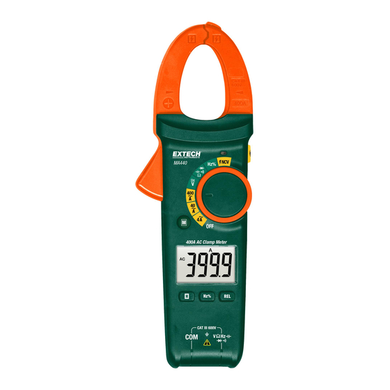
Description Meter Description Transformer current jaws Jaw opening trigger M (Mode) button Backlit LCD Control buttons (see descriptions below) COM negative input terminal Positive input terminal Function selector NCV alert symbol Backlight button (MA440) or Work Light button (MA443 and MA445) NCV sensor Note: Battery compartment is located on back of meter Fig. 1 – Meter Description Display Description Relative mode icon Units of Frequency Alternating/Direct Current Units of Voltage Negative readings Units of Capacitance Diode mode Non‐contact AC Voltage Detect Continuity mode Automatic range mode Display Hold ... -
Page 6: Control Buttons
Control Buttons Mode button: Short presses to step through the mode options for the selected measurement function HOLD and Backlight button (MA443/MA445): Short press to freeze/unfreeze reading. Long press to turn backlight ON or OFF. Note that the backlight button is in the upper right side of the meter for the MA440 (see Side Button description below) HOLD button (MA440): Short press to freeze/unfreeze reading (MA443/MA445 only) Short press to enter the maximum measurement mode (LCD displays ‘MAX’); press again to enter the minimum measurement mode (‘MIN’ is displayed). Long press to exit this mode. MAX/MIN is available on the AC Voltage/Current, Resistance, and Temperature MA445 functions only (MA445) Short press to store the displayed reading as a reference value. Subsequent measurements will be displayed as ‘measurement minus reference value’. This feature applies to AC/DC voltage, AC current, resistance, and temperature modes only. Short press to exit. For DC current measurement mode, short press to zero the display; the LCD will show the delta symbol. Short press to exit this mode. (MA440/MA443) Short press to store the displayed reading as a reference value. Subsequent measurements will be displayed as ‘measurement minus reference value’. This feature applies to AC/DC voltage, AC current, resistance, and temperature modes only. Short press to exit. (MA440 only) Short press to toggle frequency (Hz) and duty cycle (%) measurements for the Voltage and Hz switch positions. The MA443 and MA445 have a duty cycle mode accessible using the MODE button when the function dial is set to Hz%. SIDE BUTTON The button located on the upper right side of the meter is either for the LCD backlight (MA440: short press ON/OFF) or work light (MA443/MA445: Long press ON and short press OFF). MA44x‐en‐GB_V1.0 8/16 ... -
Page 7: Operation
Operation CAUTIONS Read and understand all of the Safety statements listed in the safety section of this manual prior to use. Powering the Meter Move the function switch to any position to power the meter. Check the batteries if the unit fails to power ON. Move the function switch to the OFF position to remove power to the meter. The meter has an Auto Power OFF feature (APO) where the meter switches OFF after 30 minutes (MA440) or 15 minutes (MA443/MA445) of inactivity. The MA443/MA445 models emit a warning tone prior to automatically switching off. Disable Auto Power OFF (MA443 and MA445) To defeat the APO feature: With the meter OFF, press and hold the M (MODE) button and, while continuing to hold the M button, turn the rotary switch to any position. The meter will beep five times indicating that APO has been deactivated. The Auto Power OFF function will now be disabled until the next cycle of power. When APO is active, the APO symbol is displayed. When APO is not active, the APO symbol is not displayed. MA44x‐en‐GB_V1.0 8/16 ... -
Page 8: Ac Current Measurements
AC Current Measurements WARNING: Do not handle the meter above the finger/hand guard barrier. CAUTION: Observe CAT III 600V with respect to Earth Ground for the Jaw. Rotate the function switch to the AC Current position ( for MA443 and MA445 or 4 /40 /400 for the MA440). For the MA440 start with the highest range setting (400A) and step down to lower ranges as needed, especially for signals that are of an unknown range. The A and the AC symbols will appear on the display indicating AC Amperes (Amps). The display icon AUTO will also appear indicating automatic ranging. Press the jaw trigger to open the clamp jaw. Position the clamp around only one conductor. See Fig. 2 for correct and incorrect clamp technique. Read the current in the display. The display will indicate the proper decimal point and value. NOTES: To ensure maximum accuracy, place the conductor at the center of the clamp head, otherwise additional error (± 1.0%) may apply. Do not release the trigger suddenly; the impact may lead to a change in readings since the Hall element is sensitive not only to magnetism but also to heat and mechanical stress to some extent. Fig. 2 – Correct and Incorrect ACA Clamping MA44x‐en‐GB_V1.0 8/16 ... - Page 9 DC Current Measurements (MA445) WARNING: Do not handle the meter above the finger/hand guard barrier. CAUTION: Observe CAT III 600V with respect to Earth Ground for the Jaw. CAUTION: Measure in the temperature range of 0 ~ 40 C only. Rotate the function switch to the DC Current position . The A and the DC symbols will appear on the display indicating DC Amperes (Amps). The AUTO icon will also display indicating automatic ranging. Zero any residual magnetism by pressing and holding the REL ZERO button with no conductor in the jaws. See Fig. 3 and Fig. 4 Press the jaw trigger to open the clamp jaw. Position the clamp around only one conductor. See Fig. 2 (previous section) for correct and incorrect clamping techniques. Read the current in the display. The display will indicate the proper decimal point and value. NOTES: To ensure maximum accuracy, place the conductor at the center of the clamp head, otherwise additional error (± 1.0%) may apply. If the readings are positive, the current is flowing in a downward direction (faceplate to back of meter). Do not release the trigger suddenly; the impact may lead to a change in readings since the Hall element is sensitive not only to magnetism but also to heat and mechanical stress to some extent. Fig. 3 – DCA Zero before measurement Fig. 4 – DCA Measurement MA44x‐en‐GB_V1.0 8/16 ...
-
Page 10: Ac And Dc Voltage Measurements
AC and DC Voltage Measurements WARNING: Do not apply > 600VAC/DC between the meter terminals and ground. CAUTION: When connecting the test leads to the circuit or device under test, connect the black lead before the red lead; when removing the test leads, remove the red lead before the black lead. Set the function select switch to the Voltage position . Use the M (Mode) button to select AC or DC Voltage. Insert the black test lead banana plug into the negative (COM) jack and the red test lead banana plug into the positive (V) jack. Touch the test probe tips to the circuit or under test. For DC measurements in the range of 400mV, use the Relative mode to zero the display before taking a measurement. Read the voltage in the LCD. The display will indicate the proper decimal point and value. Relative (REL) mode can be used to set a reference reading from which subsequent readings will be offset (reference reading – actual reading = displayed reading). Long press the REL button to activate/deactivate the relative mode. The MA440 can display the frequency (Hz) or duty cycle (%) of the measured voltage. Short press the Hz % button to toggle frequency and duty cycle readings. For the MA443/MA445 see the dedication section on Frequency for frequency and duty cycle. The MA443 and MA445 record MAX and MIN readings. Short press the MAX MIN button to step through the MAX MIN readings. Long press the MAX MIN button to exit. Short press the H button to freeze/unfreeze the displayed reading. Long press to activate/deactivate the display backlight. NOTES: The MA440 displays OL when the input exceeds 1000V. The MA443/MA445 display when the tested voltage is > 30V and sounds the buzzer when the voltage input is > 600V. Fig. 5 MA443/MA445 Voltage test Fig. 6 – MA440 Voltage testing MA44x‐en‐GB_V1.0 8/16 ... -
Page 11: Resistance Measurements
Resistance Measurements WARNING: Please remove power to the circuit under test and discharge all capacitors before taking resistance or continuity measurements. The meter will display OL if the circuit under test is an open circuit of if the measurement exceeds the maximum range of the meter. Do not input a voltage >30V AC or DC. ... -
Page 12: Continuity Measurements
Hz % Read the Frequency measurement on the meter display. AUTO For the MA443 and MA445, use the M (mode) button to view Duty Cycle %. For the MA440 use the Hz% button to view Duty Cycle %. ... -
Page 13: Capacitance Measurements
Capacitance Measurements WARNING: Please remove power to the circuit under test and discharge all capacitors before taking capacitance measurements. Turn the function switch to the position. Use the M (mode) button to select the capacitor display icon if necessary. Insert the black lead banana plug into the negative (COM) jack. Insert the red test lead banana plug into the positive jack. -
Page 14: Diode Test
Diode Test WARNING: Please remove power to the circuit under test and discharge all capacitors before taking diode measurements. Do not input voltages > 30V DC or AC to the meter. Turn the function switch to the position. Use the M button to select the diode icon Insert the black test lead banana plug into the negative (COM) jack and the red test lead banana plug into the positive (V) jack. - Page 15 Temperature Measurements (MA443 and MA445) WARNING: The supplied thermocouple is NOT rated for the entire specified temperature range of the meter. Please determine the range of temperature for the given application before attempting the use the supplied thermocouple. Obtain a different thermocouple if the range of the application exceeds the range of the supplied thermocouple.
- Page 16 Move the function switch to the NCV position. In this mode, the MA443 and MA445 meter will display ‘EF’ (electromotive force) and the MA440 will displays ‘OL’. These indicate that the meter is in the NCV mode but is not sensing an AC Voltage or an electromagnetic field.
-
Page 17: Maintenance
Maintenance WARNING: To avoid electrical shock, disconnect the meter from any circuit and turn OFF the meter before opening the case. Do not operate with an open case. Cleaning and Storage Periodically wipe the case with a damp cloth and mild detergent; do not use abrasives or solvents. If the meter is not to be used for 60 days or more, remove the batteries and store them separately. -
Page 18: Electrical Specifications
Function Range Resolution Accuracy (reading) ‘OL’ Protection 4.000 A* 0.001 A ± (2.5% + 30 digits) 40.00 A 0.01 A ± (1.8% + 9d) MA440 AC Current 400A ± (2.5% + 5d) 400.0 A 0.1 A MA443/MA445 *4A range on MA440 only True RMS current (MA443 and MA445 only) applicable to 10%~100% of range Frequency response: 50~60Hz (MA440 and MA443) and 40~400Hz (MA445) ... -
Page 19: Frequency (Hz)
Frequency (Hz) 10Hz~1MHz 0.01Hz~1kHz ± (0.1% + 4 digits) 600V AC/DC Sensitivity: MA440 (10Hz~1MHz): 200mVrms ≤input amplitude ≤20Vrms MA443 and MA445 (≤100kHz): 100mVrms ≤ input amplitude ≤20Vrms (100kHz~1Mz): 200mVrms ≤ input amplitude ≤20Vrms. Duty Cycle (%) 0.1 ~ 99.9% 0.1% ±... - Page 20 ‐40~40 ± (3.0% + 5 digits)* 40~400 400~1000 ± (1.0% + 3 digits)* TEMPERATURE 600V AC/DC ‐40~104 (TYPE K Thermocouple) ± (3.0% + 10 digits)* (MA443 and MA445) 104~752 752~1832 ± (1.0% + 6 digits)* *Does not include accuracy of the Type‐K temperature probe Non‐Contact ≥100Vrms; ≤10mm (0.4”) LED displays dashes, beeper sounds, and NCV lamp Voltage Detector lights (NCV)
-
Page 21: General Specifications
600V AC/DC maximum applied to any terminal Low battery indication is displayed Auto Power OFF After 30 minutes (MA440) or 15 minutes (MA443 and MA445) Hold M button while turning meter ON to disable APO (MA443 and MA445 only) Operating Temperature and Humidity 0~30C (32~86F);...
Need help?
Do you have a question about the MA440 and is the answer not in the manual?
Questions and answers