
Related Manuals for LAVAZZA LB 2801


Summary of Contents for LAVAZZA LB 2801
- Page 1 LB 2800-2801-2810-2811 MAINTENANCE MANUAL FOR TECHNICAL ASSISTANCE 10066574 / R . 2.00 / F 2012 ANUAL CODE EBRUARY...
- Page 2 LB 2800 Machine code 10080022 LB 2801 Machine code 110080118 LB 2810 Machine code 10080005 LB 2811 Machine code 10080023 Manual code 10066574 Rel. 2.00 Edition 02/2012 www.absoluteaftersales.it © Copyright LAVAZZA S.p.A. Tel. 0039.011.2348429 Fax 0039.011.23480466 technicalservice@lavazza.it Certificated n° IT09/0445...
-
Page 3: Table Of Contents
Maintenance manual for technical assistance TABLE OF CONTENTS 5. INSTALLATION AND START UP ... . . 9 1. GENERAL INFORMATIONI ....1 5.1. - Page 4 Maintenance manual for technical assistance 9.3.1. Cappuccinatore (only LB 2800 - LB 2810 models) ......20 9.3.2.
-
Page 5: General Informationi
Service site at the following address: http://ts.inla- rancies due to misprint. vazza.it. It is recommended that the Internet site of the Lavazza Technical Service be checked (at the following address 1.2. Designated personnel http://ts.inlavazza.it) to ensure that your manual is the... -
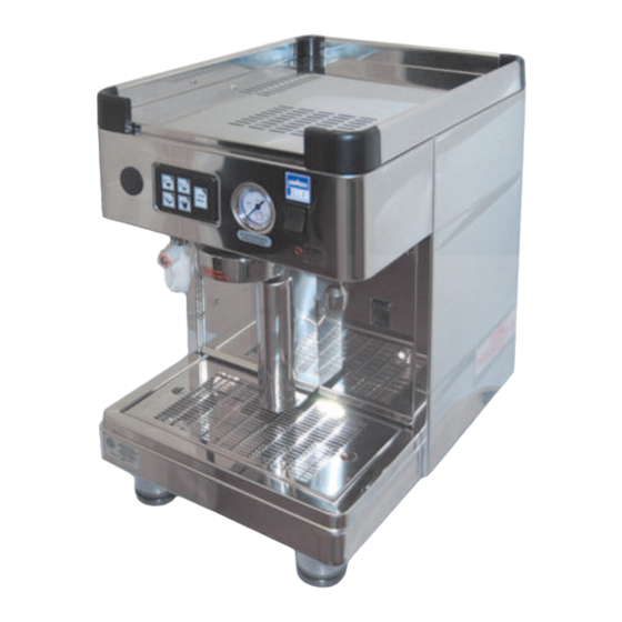
Page 6: Machine Composition
Coffee brewing pressure (bar): 8 - 9 max LB 2800 - LB 2810 Power supply voltage (V): 230 Power consumption (W): 1700 LB 2801 - LB 2811 Power supply voltage (V): 120 LB 2801 - LB 2811 Power consumption (W): 1350 1.3.5. -
Page 7: Internal Components
LB 2800 - LB 2810 1.3.6.1. Boiler The boiler (A) is constructed of steel. A heat exchanger LB 2801 - LB 2811 connected to the brewing unit is attached to the boiler. Water for coffee brewing is taken directly from the heat exchanger. -
Page 8: Brewing Unit
Maintenance manual for technical assistance 1.3.6.2. Brewing unit Note If the water temperature in the boiler is decreased The brewing unit and the heat exchanger are funda- but the coffee is still too hot, the reducer (5) supplied mental components to obtain espresso coffee. with the machine must be put on the pipe. -
Page 9: Flowmeter
Maintenance manual for technical assistance 1.3.6.4. Flowmeter - connect a pressure gauge, with bottom scale greater than 9 bars, to the specific fitting on the water circuit The flowmeter installed on the EVD electronic machines, (see the hydraulic diagram); measures the quantity of water sent to the brewing unit for espresso brewing. -
Page 10: Electronic Control Unit
Accessories: The main safety precautions that should be used when A) Rifle-type brush operating the machine are described below. Lavazza B) Brush with bristles does not foresee every possible situation that could be C Detergent for cappuccinatore potentially dangerous. -
Page 11: Stop Functions
The careful hazardous analysis performed, has allowed most of the risks connected with operating and mainte- - enter into contact with any type of liquid; nance machine conditions to be eliminated. Lavazza re- - be manipulated by humid or wet hands; - be tampered with. -
Page 12: Handling And Storage
Maintenance manual for technical assistance carried out, the opening of any part of the hydraulic cir- The crossed-out wheeled bin symbol displayed cuit can cause a sudden outlet of overheat water under on the appliance and/or the packaging indicates pressure. that at the end of its life, the product should not be treated as a generic household waste but should be - Be careful with the tips of the capsule perforator loca-... -
Page 13: Positioning
Maintenance manual for technical assistance posed and disposed of according to the waste col- and to be able to immediately leave the area in an lection and disposal regulation in force. emergency. 5.2. Positioning Prepare a support base that is suitable to support its weight (1);... -
Page 14: Electric Connection
Maintenance manual for technical assistance Note Note All filling connections are 3/8 male gas type. The All the machines are equipped with an automatic drain tray is connected with a pipe of 16 mm. inter- water filling with a time control device which allows nal diameter. -
Page 15: Recommended Tools
Maintenance manual for technical assistance Attention During the machine’s warm-up phase (about 20 mi- nutes), the safety valve will release steam for a few seconds until the valve itself closes. Before using the machine, carry out some dry cy- cles with the capsule holders attached for a few se- conds, to release any air which may be in the circuit, so that the brewing units are completely heated. -
Page 16: Configuration
Maintenance manual for technical assistance 7. CONFIGURATION 7.1. Machine alarms The pilot light of the key dose is flashing: abnormal or absent reading of the dose during dispensing. LEDS of the keyboard are flashing: the Time-out device is activated. 7.2. Programming Attention 7.2.2. -
Page 17: Hot Water Dispensing
Maintenance manual for technical assistance Turn it clockwise to reduce and anticlockwise to in- Note crease cold water . Each dose should be programmed using a new cap- sule and not one previously used. 7.2.3. Hot water dispensing Put the programming lever (1), situated under the ma- chine boiler cover, to the ON position. -
Page 18: Loading Of Default Data
- When the programming is completed, turn the pro- gramming lever (1) to the OFF position. LB 2801 Note LB 2811 In order to obtain a temperature lower than the mi- nimum value set, the reducer of Ø... -
Page 19: Preparation Of Hot Drinks
Maintenance manual for technical assistance Dispensing steam (only LB 2801-LB 2811 models) Insert a capsule into the capsule holder, attach the cap- Immerse the steam nozzle (4) in the liquid to be heated. sule-holder to the brewing unit and tighten it firmly. -
Page 20: Cappuccinatore
Maintenance manual for technical assistance 7.2.9. Cappuccinatore (only LB 2800-LB 2810 mo- dels) Note For proper use of the automatic cappuccinatore, al- Preparing cappuccino ways use the capsule-holder with the long spout. Immerse the suction pipe (1) in the milk. Insert a capsule into the capsule holder, attach the cap- To change the milk temperature, install one of the sup- sule-holder to the brewing unit and tighten it firmly. -
Page 21: Diagrams
Maintenance manual for technical assistance 8. DIAGRAMS 8.1. Electrical diagram (CAL) Boiler (CCP) Keyboard connection cable (CN9) Brewing unit connector (CPR) Programming key (CV) Flowmeter (EVG) Brewing unit solenoid valve (EVC) Boiler filling solenoid valve (EVV) Steam solenoid valve (F1) Fuse T10 A (F2) Fuse T500 mA... -
Page 22: Hydraulic Diagram
Maintenance manual for technical assistance 8.2. Hydraulic diagram Hot water dispensing Cappuccinatore Coffee dispensing Water entry Discharge 01) Water entry filter 14) Brewing unit solenoid valve 02) Built-in power pump 15) Solenoid valve of Automatic Water Entry 03) Adjusting screw of pump pressure system 04) Pump pressure gauge cap 16) Coffee exchanger... -
Page 23: Inspections And Maintenance
Maintenance manual for technical assistance 9. INSPECTIONS AND MAINTENANCE 9.1. Periodical inspections Every week check the boiler pressure using the machine pressure gauge. Note The boiler pressure must be 0.8-1.2 bar. Every four months check the gaskets of the brewing unit (for brewing unit disassembling see the section 9.2.1). -
Page 24: Replacing The Perforator
Maintenance manual for technical assistance 9.2.3. Replacing the perforator Attention To replace the perforator proceed as follows: During cleaning, be careful with the tips of the cap- sule perforator located inside the clamping ring of - with a small screwdriver, remove the spring (1) that the unit. -
Page 25: Capsule-Holder
Maintenance manual for technical assistance D) Keep the STOP/PROG key pressed (3) for 8 se- L) Place the lower body (4) back to the position (X). conds, until the corresponding LED lights up; M) If the air inlet hole is clogged (5), clear it with a nee- dle carefully. -
Page 26: Troubleshooting
Maintenance manual for technical assistance 10. TROUBLESHOOTING 10.1. Signalling and solutions to the most common problems PROBLEM CAUSE SOLUTION The on/off switch is placed to “0” position. Place the on/off switch to “I” position. The on/off switch is damaged. Replace the on/off switch. No electrical power on the ma- chine. - Page 27 Maintenance manual for technical assistance PROBLEM CAUSE SOLUTION The drain tray does not discharge. Check the sewer drain. The drain pipe is broken or detached or Check and restore the connection of Water leaks from the machine. clogged. the drain pipe to the drain tray. Check and eliminate any hydraulic Water leaks in the hydraulic circuit.
- Page 28 Maintenance manual for technical assistance PROBLEM CAUSE SOLUTION The boiler temperature is too high. Reduce the temperature in the boiler. Coffee is too hot. The flow reducer of the brewing unit is Replace the reducer with one of a not suitable. smaller diameter.
- Page 29 Maintenance manual for technical assistance PROBLEM CAUSE SOLUTION The connection of the flowmeter is de- Check for proper connection of the fective. flowmeter. Check for proper connection of the 8- The connection of the electronic control pin connector of the electronic control unit is defective.
- Page 30 Maintenance manual for technical assistance PROBLEM CAUSE SOLUTION Poor mechanical seal of the shaft or the Check the pump and take any cor- O-Ring. rective actions. The inlet and outlet connections are Tighten the connectors. loose. The pump leaks water. the hexagonal nut of the pressure relief Tighten the hex connection of the valve or the filter are loose.
- Page 31 Maintenance manual for technical assistance PROBLEM CAUSE SOLUTION Steam pockets during brewing. Reduce the water temperature. The cup is dirty with splashed Tighten fittings or connectors which Air pockets in the hydraulic circuit. coffee. are loose. The flow reducer of the brewing unit is Replace the flow reducer.
Need help?
Do you have a question about the LB 2801 and is the answer not in the manual?
Questions and answers