Advertisement

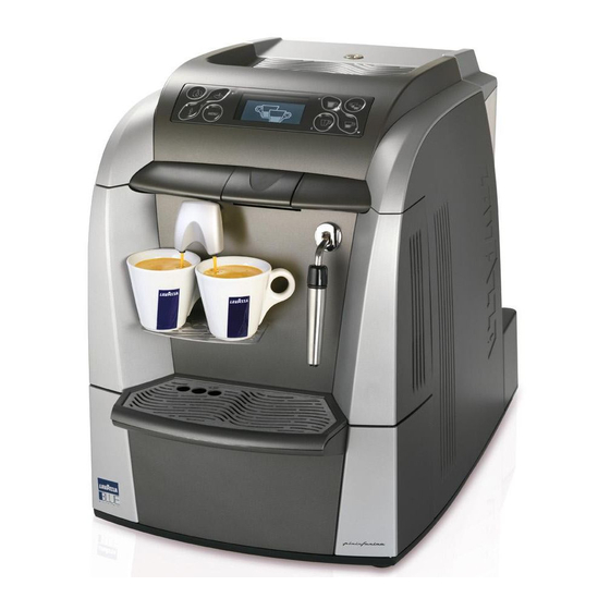
LB 2300-2301-2302-2311-2312
MAINTENANCE MANUAL FOR
TECHNICAL ASSISTANCE
M
10083445 / R
. 0.00 / A
2010
ANUAL CODE
EL
PRIL

Advertisement

Table of Contents
loading

Summary of Contents for LAVAZZA LB 2300

  • Page 1 LB 2300-2301-2302-2311-2312 MAINTENANCE MANUAL FOR TECHNICAL ASSISTANCE 10083445 / R . 0.00 / A 2010 ANUAL CODE PRIL...
  • Page 2 LB 2300 Single cup 230 V Machine code 10080606 LB 2301 Single cup 230 V Steam Machine code 10080618 LB 2302 Double cup 230 V Steam Machine code 10080712 LB 2311 Single cup 120 V Steam Machine code 10080631 LB 2312 Double cup...
  • Page 3: Table Of Contents

    Maintenance manual for technical assistance LB 2300-2301-2302-2311-2312 Index GENERAL INFORMATION ....... 1 1.1.
  • Page 4 Maintenance manual for technical assistance LB 2300-2301-2302-2311-2312 USER MENU ......... 9 6.1.
  • Page 5 Maintenance manual for technical assistance LB 2300-2301-2302-2311-2312 11.9. Pump disassembly ......47 11.10.
  • Page 7: General Information

    Maintenance manual for technical assistance LB 2300-2301-2302-2311-2312 1. GENERAL INFORMATION The manufacturer is not responsible for damage deri- ved from the failure to follow this rule. 1.1. Designated personnel 1.2.3. Preservation The machine may be operated only by a qualified techni-...
  • Page 8: Machine Composition

    Maintenance manual for technical assistance LB 2300-2301-2302-2311-2312 1.2.5. Machine composition Note: if not expressly indicated in the text, the position numbers of the machine parts are referred to this figure. 1 Control panel 2 Capsule loading tray 3 Steam/hot water pipe (according to the model)
  • Page 9: Internal Components

    Maintenance manual for technical assistance LB 2300-2301-2302-2311-2312 1.2.6. Internal components 1 Steam solenoid valve 12 Gear motor 2 Pressure relief valve 13 Pump 3 Power board 14 Boiler 4 On/off switch 15 Capsule release coil 5 Safety fuses 16 CPU board...
  • Page 10: Range

    Maintenance manual for technical assistance LB 2300-2301-2302-2311-2312 1.2.7. Range Dispensing spout for 1 product (A) SINGLE CUP LB 2300 Cap 01 Dispensing spout for 1 product (B) Steam/hot water pipe SINGLE CUP WITH STEAM WITH STEAM Dispensing spout for 2 products (C)
  • Page 11: Machine Identification Data

    Maintenance manual for technical assistance LB 2300-2301-2302-2311-2312 1.2.8. Machine identification data Operating conditions: Minimum temperature: 10°C In the plate the following identification data of the Maximum temperature: below 40° machine are indicated: Maximum humidity: below 95% - Manufacturer; Brewing temperature: - Machine name;...
  • Page 12: General Safety Rules

    Maintenance manual for technical assistance LB 2300-2301-2302-2311-2312 2. GENERAL SAFETY RULES 2.1. Stop functions To stop the machine turn the main switch to “0” (OFF). Attention Read the entire manual carefully and the follo- 2.2. Safety devices wing general safety rules..
  • Page 13: Installation

    Maintenance manual for technical assistance LB 2300-2301-2302-2311-2312 3. INSTALLATION Use of the appliance This espresso coffee machine is an appliance for pro- 3.1. Unpacking fessional use only. Any other type of use is considered Open the packaging, taking care not to damage it.
  • Page 14: Machine Positioning

    Maintenance manual for technical assistance LB 2300-2301-2302-2311-2312 5. DISMANTLING 3.3. Machine positioning Note Environment For a correct ergonomic use of the machine, place Disposal of machine components after dismantling, it on a working surface not lower than one meter should be carried out with respect for the environ- from the floor.
  • Page 15: User Menu

    Maintenance manual for technical assistance LB 2300-2301-2302-2311-2312 6. USER MENU DOUBLE CUP WITH STEAM 1 1 0 0 SINGLE CUP WITH STEAM WITH STEAM SINGLE CUP 1 1 1 1 LB 2300 Cap 01 Manual code 10083445 / Rel. 0.00 / April 2010...
  • Page 16 Maintenance manual for technical assistance LB 2300-2301-2302-2311-2312 BUTTON DESCRIPTION 01) Hot water dispen- Press this button for 1 second and the machine immediately dispenses hot water. sing Press this button for 1 second and the machine immediately dispenses steam. 02) Steam dispensing...
  • Page 17: Machine Warnings

    Maintenance manual for technical assistance LB 2300-2301-2302-2311-2312 BUTTON DESCRIPTION 02) Enter/Confirm Press the button to select the function or confirm the command. 06) Page UP Press the button to change function or parameter. 08) ESC Press the button to exit the function.
  • Page 18 Maintenance manual for technical assistance LB 2300-2301-2302-2311-2312 DISPLAY MEANING ACTIONS The tray has been closed with a capsule Dispense the product. inside. Stop the dispensing by pressing the hot The machine is dispensing hot water. water button. Stop the dispensing by pressing the steam The machine is dispensing steam.
  • Page 19 Maintenance manual for technical assistance LB 2300-2301-2302-2311-2312 DISPLAY MEANING ACTIONS The machine is performing the pre-infu- Wait for the product brewing to restart auto- sion cycle and stops brewing the product. matically. The machine has started the product bre- Wait for the brewing automatically or wing cycle.
  • Page 20: Machine Programming (Service Provider)

    Maintenance manual for technical assistance LB 2300-2301-2302-2311-2312 DISPLAY MEANING ACTIONS Wait for this operation to be successfully The machine is filling the hydraulic circuit. completed. The descaling filter must be replaced. Request assistance from the service provider. Turn the machine on using the on/off switch and while 6.2.
  • Page 21: Programming Commands

    Maintenance manual for technical assistance LB 2300-2301-2302-2311-2312 Attention The chosen PASSWORD (default 0000), should be changed during the first machine start up in such away to prevent unauthorised access. It is possible to change the password using either the service or the programming menu.
  • Page 22: Table Of Programming Menu

    Maintenance manual for technical assistance LB 2300-2301-2302-2311-2312 6.4. Table of programming menu 1. Programming menu Press ENTER to access the programming menu Set value Enter the previously stored password (4 digits) Password Enter password Default: 0000 for accessing the password function 1.1.1.
  • Page 23 Maintenance manual for technical assistance LB 2300-2301-2302-2311-2312 (Read only) Yes: the machine checks the remaining credits. 1.2.7.Credits 1.2.7.1.Credit check No: The machine does not check remaining credit. “Yes” enables - display of the credit alarm signal when the 1.2.7.2.Credit warning...
  • Page 24 Maintenance manual for technical assistance LB 2300-2301-2302-2311-2312 “Yes” enables operation of the cup warmer 1.4. 1.4.1. Activate? plate (only for models equipped with a cup Default: No Cup warmer warmer plate) 1.5.1. Password Set of the menu access password 1.5. Security...
  • Page 25 Maintenance manual for technical assistance LB 2300-2301-2302-2311-2312 Number of product type 3 (manual dose) dispen- 2.2.1.4. Prod.3 from reset sed since the last Reset Number of product type 4 (double espresso) 2.2.1.5. Prod.4 from reset dispensed since the last Reset 2.2.1.
  • Page 26 Maintenance manual for technical assistance LB 2300-2301-2302-2311-2312 2.5.1.Do it now “Yes” starts the descaling cycle Default: No 2.5.2. (Read only) 2.5. Last descaling Date and time of last descaling cycle Descaling (Read only) 2.5.3. Water quantity (litres) to be dispensed before the...
  • Page 27: Parameter Change

    1.2.1. Temperatura std Maintenance manual for technical assistance LB 2300-2301-2302-2311-2312 6.6. Parameter change When the last digit is changed, press “OK” to confirm. The " " symbol disappears and the parameters become active only upon exit the programming mode. Attention When one of the machine’s operational parameter...
  • Page 28: Diagrams

    Maintenance manual for technical assistance LB 2300-2301-2302-2311-2312 7. DIAGRAMS 7.1. Wiring diagram LB 2300 Schema di cablaggio LB2300 Base LB 2300 Cap.04 Manual code 10083445 / Rel. 0.00 / April 2010 REV00 - Dicembre 2008...
  • Page 29 Maintenance manual for technical assistance LB 2300-2301-2302-2311-2312 LB 2301 - LB 2302 - LB 2311 - LB 2312 Schema di cablaggio LB2300 Top LB 2300 Cap.04 Manual code 10083445 / Rel. 0.00 / April 2010 REV00 - Dicembre 2008...
  • Page 30: Hydraulic Diagram

    Maintenance manual for technical assistance LB 2300-2301-2302-2311-2312 7.2. Hydraulic diagram LB 2300 Schema idraulico LB2300 Base LB 2300 Cap.04 REV00 - Dicembre 2008 Manual code 10083445 / Rel. 0.00 / April 2010...
  • Page 31 Maintenance manual for technical assistance LB 2300-2301-2302-2311-2312 LB 2301 - LB 2302 - LB 2311 - LB 2312 Schema idraulico LB2300 Top LB 2300 Cap.04 REV00 - Dicembre 2008 Manual code 10083445 / Rel. 0.00 / April 2010...
  • Page 32: Troubleshooting

    Maintenance manual for technical assistance LB 2300-2301-2302-2311-2312 8. TROUBLESHOOTING LB 2300 Single cup 8.1. Test mode Line 1: Displays the test mode level Line 2: Displays microswitches/sensors Attention Line 3: Displays the pressed button Line 4: Displays the value of the machine component Be careful when the test mode is activated;...
  • Page 33 Maintenance manual for technical assistance LB 2300-2301-2302-2311-2312 LB 2301 - LB 2311 Single cup with steam LB 2302 - LB 2312 Double cup with steam Line 1: Displays the test mode level Linea 1: Visualizzazione livello Test Mode Line 2: Displays microswitches/sensors...
  • Page 34 Maintenance manual for technical assistance LB 2300-2301-2302-2311-2312 TEST MODE 1 By pressing DOWN the coffee solenoid In this level the operation of the brew unit and the valve is activated. capsule release coil are tested By pressing UP the gear motor drives the brew unit to the upper position (working Press CANCEL to activate the pump;...
  • Page 35 Maintenance manual for technical assistance LB 2300-2301-2302-2311-2312 By pressing the enter button the next By pressing the enter button the next test mode level is reached (level 6). test mode level is reached (level 4). TEST MODE 4 TEST MODE 6...
  • Page 36: Troubleshooting

    Maintenance manual for technical assistance LB 2300-2301-2302-2311-2312 8.3. Troubleshooting This chapter indicates the troubleshooting procedures to follow when a fault is signalled by the machine. Error code What has happened Possible cause Where to find the cause The capsule is deformed and/or...
  • Page 37 Maintenance manual for technical assistance LB 2300-2301-2302-2311-2312 Error code What has happened Possible cause Where to find the cause The sensor of the water level is broken The sensor of the turbine is broken The pipe of the water circuit is...
  • Page 38 Maintenance manual for technical assistance LB 2300-2301-2302-2311-2312 Error code What has happened Possible cause Where to find the cause The temperature sensor is broken The temperature sensor is not connected The wire of the temperature sensor is disconnected Room temperature for instal-...
  • Page 39 Maintenance manual for technical assistance LB 2300-2301-2302-2311-2312 Error code What has happened Possible cause Where to find the cause The capsule is blocked on the brew unit The brew unit is jammed or bloc- The motor has exceeded the maxi- Maximum effort for brewing.
  • Page 40 Maintenance manual for technical assistance LB 2300-2301-2302-2311-2312 Error code What has happened Possible cause Where to find the cause The gear motor power is insuffi- cient and not appropriate The microswitch for working posi- tion is broken or disconnected The motor of the gear motor...
  • Page 41: Operational Logic

    Maintenance manual for technical assistance LB 2300-2301-2302-2311-2312 9. OPERATIONAL LOGIC hypothesis 3) a double coffee of 110 cc is selected, the first product is partially dispensed 100 cc, the message “fill the tank” 9.1. Reset of used capsule drawer appears and then the second product The warning message “empty used capsule drawer”...
  • Page 42: Recommended Tools

    Maintenance manual for technical assistance LB 2300-2301-2302-2311-2312 10. RECOMMENDED TOOLS To carry out the appliance maintenance you need the following tools: Torx screwdriver T10 Crosshead screwdriver PH1 Crosshead screwdriver PH2 Flat screwdriver 0.8 x 4 x 80 Open ended spanner 10 mm...
  • Page 43: Mounting And Disassembly Of The Machine

    Maintenance manual for technical assistance LB 2300-2301-2302-2311-2312 11. MOUNTING AND DISASSEMBLY OF THE MACHINE COMPONENTS 11.1. Upper body Remove the used capsule drawer; separate and dispose of the used capsule; empty the waste water. Loosen the indicated screws. Press the “PUSH” button and remove the brewing unit from its seat.
  • Page 44 Maintenance manual for technical assistance LB 2300-2301-2302-2311-2312 Remove the water tank lid using the key. Remove the water tank by lifting it up using its handle. Loosen the body screws and the fixing nut of the tum- bler lock. Manual code 10083445 / Rel. 0.00 / April 2010...
  • Page 45 Maintenance manual for technical assistance LB 2300-2301-2302-2311-2312 Loosen the indicated screws which fix the body to the machine bottom. Lift the body up gently, as indicated in the figure. For the version equipped with cup warmer, remove the power supply connector of the cup warmer and the ground faston connector (now the body is disengaged).
  • Page 46 Maintenance manual for technical assistance LB 2300-2301-2302-2311-2312 When the connectors are removed extract the body completely. Extract the indicated pin with force to remove the front panel. Remove the clip which fixes the steam pipe to the door and extracts the pipe from its seat.
  • Page 47: Gaco Gasket Replacement

    Maintenance manual for technical assistance LB 2300-2301-2302-2311-2312 It is possible to access the internal components to check their operation. Attention Now the machine has no shielding; in the machi- ne there are electrical components and compo- nent which generate heat. Be careful when ope- rating under these conditions.
  • Page 48: Power Cord Replacement

    Maintenance manual for technical assistance LB 2300-2301-2302-2311-2312 11.3. Power cord replacement Remove the indicated screws Inside the compartment there are : 1) the receptacle of the power cord 2) the fuse housing Manual code 10083445 / Rel. 0.00 / April 2010...
  • Page 49: Connector Compartment

    Maintenance manual for technical assistance LB 2300-2301-2302-2311-2312 11.4. Connector compartment Remove the indicated screw and the black cover. 1) Infrared interface for diagnostic and reprogramming of the machine parameters and software. 2) Connector for payment systems 3) Serial port for P.C. for reprogramming of the machine parameters and software.
  • Page 50: Steam Pipe Disassembly

    Maintenance manual for technical assistance LB 2300-2301-2302-2311-2312 11.5. Steam pipe disassembly Disassemble the steam pipe by using a spanner. Remove the steam pipe. 11.6. Steam solenoid valve disassembly Disconnect the faston, loosen the nut and remove the coil. Manual code 10083445 / Rel. 0.00 / April 2010...
  • Page 51 Maintenance manual for technical assistance LB 2300-2301-2302-2311-2312 Remove the clip which fixes the pipe to the Teflon piece by using a screwdriver. Loosen the indicated screws. Loosen the indicated screws. Manual code 10083445 / Rel. 0.00 / April 2010...
  • Page 52: Cup Warmer Plate Disassembly

    Maintenance manual for technical assistance LB 2300-2301-2302-2311-2312 11.7. Cup warmer plate disassembly (If it is supplied) Overturn the cover and loosen the indicated screws. Reposition the cover correctly and remove the cup warmer plate. Remover the gasket and replace it if necessary.
  • Page 53: Capsule Release Coil Disassembly

    Maintenance manual for technical assistance LB 2300-2301-2302-2311-2312 11.8. Capsule release coil disassembly Remove the thermal protector from its seat and disconnect the electric wires. The capsule release coil should be disassembled by lowering the stop on the back. 11.9. Pump disassembly...
  • Page 54: Turbine Disassembly

    Maintenance manual for technical assistance LB 2300-2301-2302-2311-2312 11.10. Turbine disassembly Extract the turbine by lifting it upwards. Disconnect the electrical connection. Disconnect the hydraulic connections. Manual code 10083445 / Rel. 0.00 / April 2010...
  • Page 55 Maintenance manual for technical assistance LB 2300-2301-2302-2311-2312 Remove the turbine from the machine. Turn the turbine top to open it. Clean the rotary section of the turbine. Manual code 10083445 / Rel. 0.00 / April 2010...
  • Page 56: Capsule Release Unit Disassembly

    Maintenance manual for technical assistance LB 2300-2301-2302-2311-2312 11.11. Capsule release unit disassembly Loosen the indicated screws and remove the capsule presence microswitch. Remove the upper support from the base lifting it up. Loosen the indicated screws to access the inside of the unit.
  • Page 57 Maintenance manual for technical assistance LB 2300-2301-2302-2311-2312 In this case it is possible to reach the microswitch that controls if the capsule loading tray is open. To remove the microswitch lightly widen the two stops and lift it up. The unit can be checked by removing it from its seat as indicated in the figure.
  • Page 58: Capacitive Sensor Disassembly

    Maintenance manual for technical assistance LB 2300-2301-2302-2311-2312 11.12. Capacitive sensor disassembly Remove the capacitive sensor from its seat. Loosen the indicated screw to access the sensor. The capacitive sensor is maintained in its seat by an adhesive film. Manual code 10083445 / Rel. 0.00 / April 2010...
  • Page 59: Transformer Disassembly

    Maintenance manual for technical assistance LB 2300-2301-2302-2311-2312 11.13. Transformer disassembly The transformer is situated under the board on the right side of the machine. Loosen the indicated screws. Loosen the indicated screws. Manual code 10083445 / Rel. 0.00 / April 2010...
  • Page 60 Maintenance manual for technical assistance LB 2300-2301-2302-2311-2312 Lift the plate up. Loosen the indicated screws. Manual code 10083445 / Rel. 0.00 / April 2010...
  • Page 61: Coffee Thermostat Disassembly

    Maintenance manual for technical assistance LB 2300-2301-2302-2311-2312 11.14. Coffee thermostat disassembly Disconnect the electric connections of the thermostats (A). Loosen the indicated screw. Lever with a screwdriver to disengage the retainer. Manual code 10083445 / Rel. 0.00 / April 2010...
  • Page 62: Boiler Disassembly

    Maintenance manual for technical assistance LB 2300-2301-2302-2311-2312 Remove the retainer and the thermostats. 11.15. Boiler disassembly Unscrew the nut (X), remove the fork and the Teflon pipe (Y) and (W), disconnect the silicone pipe (Z). Loosen the indicated screws. Manual code 10083445 / Rel. 0.00 / April 2010...
  • Page 63: Gear Motor Disassembly

    Maintenance manual for technical assistance LB 2300-2301-2302-2311-2312 Remove the boiler and the pin from the plate. After extracting the boiler, it is possible to disassemble the solenoid valve (H). 11.16. Gear motor disassembly It is possible to access the microswitch of the used capsule drawer presence (X).
  • Page 64: Perforator Filter Disassembly

    Maintenance manual for technical assistance LB 2300-2301-2302-2311-2312 11.17. Perforator filter disassembly Remove the brew unit. Loosen the indicated screws. Loosen the indicated screws. Manual code 10083445 / Rel. 0.00 / April 2010...
  • Page 65 Maintenance manual for technical assistance LB 2300-2301-2302-2311-2312 Widen lightly the brew unit sides and extract the fixed container of the coffee capsule. Loosen the indicated screws. Remove the perforator. Manual code 10083445 / Rel. 0.00 / April 2010...
  • Page 66 Maintenance manual for technical assistance LB 2300-2301-2302-2311-2312 To remove the piston, lever with a screwdriver on the rod to disengage it. When the pin is disengaged press it with a finger to remove it from its position. Extract the piston from the top.
  • Page 67 Maintenance manual for technical assistance LB 2300-2301-2302-2311-2312 Once the piston is removed the gasket can be repla- ced easily. To mount the piston, insert it again in its position as indicated in the figure. Keeping pressed the piston, press the rod into the slit of the piston until it is fixed in place.
  • Page 68 Maintenance manual for technical assistance LB 2300-2301-2302-2311-2312 Then the fixed container should be mounted. Grease, with food safe silicone grease, the rails of the two inner sides of the brew unit. Grease, with food safe silicone grease the connecting rod and the rod.
  • Page 69: Power Board Disassembly

    Maintenance manual for technical assistance LB 2300-2301-2302-2311-2312 11.18. POWER board disassembly Attention This operation must only be performed with the machine switched off.. The POWER board is situated on the side of the machine. The transformer is situated under the POWER board.
  • Page 70: Keyboard Board Disassembly

    Maintenance manual for technical assistance LB 2300-2301-2302-2311-2312 11.20. Keyboard board disassembly Disconnect the flat cable which connect the two capa- citive boards and loosen the indicated screws to access the keyboard boards. Remove the gasket by lift it up. The two boards are attached with an adhesive, lever to remove them.
  • Page 71: Display Disassembly

    Maintenance manual for technical assistance LB 2300-2301-2302-2311-2312 11.21. Display disassembly Disconnect the two indicated connections. Detach the flat cable that connect the two capacitive boards and loosen the indicated screws to access the keyboard boards. Remove the display and replace it.
  • Page 72: Assembly And Removal Of The Oetiker Clamps

    Maintenance manual for technical assistance LB 2300-2301-2302-2311-2312 11.22. Assembly and removal of the OETIKER clamps To tighten the clamp use the proper pliers. Check the correct clamping (A) and positioning. To remove the clamp use the pincers as indicated in the figure (B).

This manual is also suitable for:

Lb 2301Lb 2312Lb 2302Lb 2311

Table of Contents