Table of Contents
Advertisement
Advertisement
Table of Contents

Subscribe to Our Youtube Channel
Related Manuals for Seaward Solar PV150


Summary of Contents for Seaward Solar PV150
- Page 1 Solar Installation PV150 Operating Instructions Bracken Hill South West Industrial Estate Peterlee Co Durham SR8 2SW ENGLAND Tel: +44(0)191 5863511 www.seaward.co.uk sales@seaward.co.uk service@seaward.co.uk Part Number 388A567 Revision 4 February 2017 © 2017 Seaward Electronic...
-
Page 2: Limited Warranty & Limitation Of Liability
SEAWARD Electronic Limited guarantees this product to be free from defects in material and workmanship under normal use and service for a period of 2 year, provided that the instrument is serviced and calibrated by a Seaward approved agent in accordance with the manufactures instructions. The period of warranty will be effective at the day of delivery. -
Page 3: Table Of Contents
7.6 Operating Current (via AC/DC Current Clamp) ..............18 8 Environmental Conditions ......................19 9 Maintenance ..........................20 9.1 Preparing to work on the Solar PV150................. 20 9.2 Securing the Solar PV150 ....................20 9.3 Cleaning the Solar PV150 ....................20 9.4 Battery Replacement...................... -
Page 4: Certificate Of Conformity
Performance: The instrument operates within specification when used under the conditions in the above standards EMC and Safety Standards. The product identified above conforms to the requirements of Council Directive 2004/108/EC and 2006/95/EC. Seaward Electronic Ltd is registered under BS EN ISO9001:2000 Certificate No: Q05356. - 4 -... -
Page 5: Introduction
Solar Installation PV150 Operating Instructions Introduction The Solar Installation PV150 is a hand held, battery powered, multi-function solar photovoltaic installation test instrument capable of performing all of the electrical tests required by IEC 62446, including: Earth continuity @ 200mA Open circuit module, string or array voltage Voltage polarity Short circuit module, string or array current Insulation resistance at 250V, 500V and 1000V... -
Page 6: Accessories
Solar Installation PV150 Operating Instructions Do not touch any exposed metal parts of the solar PV installation during testing. Always ensure that the circuit under test is electrically isolated from the mains supply before attempting an earth resistance measurement. Do not leave the PV150 permanently connected to a PV installation. Always disconnect all test leads immediately after use. -
Page 7: Unit Description
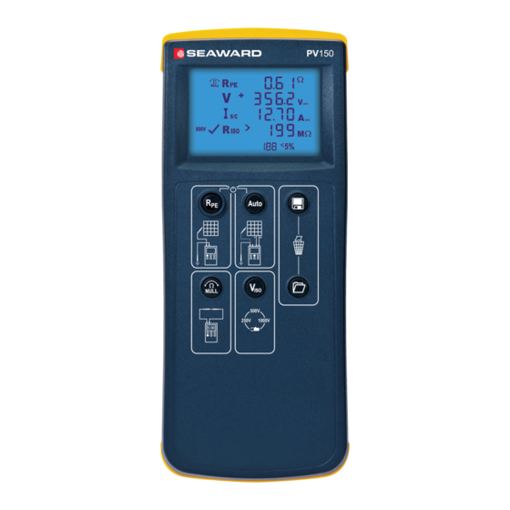
Solar Installation PV150 Operating Instructions 4 Unit Description The Solar Installation PV150 is a hand held, multi-function electrical installation test instrument. 4.1 Identifying parts of the unit The numbering below refers to figure 1 and figure 2. Figure 2 PV150 End view 1. -
Page 8: Lcd Display
Solar Installation PV150 Operating Instructions 2 LCD display Figure 3 LCD display icons a. Rpe voltage polarity. For AC voltages alternating + and – is shown. b. Current clamp measurement active. c. Rpe Null offset - indicates that test lead resistance offset is active. d. -
Page 9: Using The Solar Installation Pv150
Solar Installation PV150 Operating Instructions Using the Solar Installation PV150 5.1 Power On Solar PV150 To turn the PV150 on, press and hold the Rpe and Auto buttons simultaneously. 5.2 Battery Condition Check The PV150 automatically performs battery condition checks whilst idle and during measurements. -
Page 10: Resistance Measurement
Solar Installation PV150 Operating Instructions 5.3.2 Resistance measurement To make a single measurement: 1. Connect the red and black test leads as shown. 2. Press the Rpe key. 3. The resistance between the test probes is displayed. To make a continuous measurement: Connect the red and black test leads as shown. -
Page 11: Auto Sequence Measurement
Use the Viso button to select either the 250V, 500V or 1000V insulation test voltage, please refer to relevant standards for testing requirements. Press the Auto button and the Solar PV150 will automatically perform the following tests: Open Circuit Voltage... -
Page 12: Memory Store
Operating Instructions 5.5 Memory Store The Solar PV150 can store up to 200 complete sets of measurements. Press the Memory Store button to store all measured values on the display. If there is sufficient memory space to store a set of readings, then the Store icon will appear, and the readings will be stored in the next available memory location. -
Page 13: Operating Current
Solar Installation PV150 Operating Instructions 5.8 Operating Current The PV150 can be used to measure the DC operating current of a solar PV installation as shown. 1. Disconnect all cables from the PV test inputs (8 & 9 in figure 2). 2. -
Page 14: Dc Operating Power
Solar Installation PV150 Operating Instructions 5.9 DC Operating Power The PV150 can be used to measure the DC operating power of a solar PV installation as shown. Disconnect all cables from the PV test inputs (8 & 9 in figure 2). Connect the current clamp to the red –... -
Page 15: Auto Shutdown
Solar Installation PV150 Operating Instructions 5.10 Auto Shutdown After 1 minute of being idle the PV150 will turn itself off in order to conserve battery power. This auto shutdown period can be extended as follows: 1. Turn the PV150 unit off 2. -
Page 16: Use With The Solar Survey 200R
Solar Installation PV150 Operating Instructions Use with the Solar Survey 200R 6.1 Pairing with the Survey 200R Make sure there are no other units operating nearby. Turn off both the PV150 and Survey 200R unit. On the Survey 200R, press and hold the On/Off keys, keep both keys pressed. On the PV150, press and hold the Rpe and Auto keys, keep both buttons pressed. -
Page 17: Downloading Data To Pc
Connect the PV150 to PC using the USB cable. (This will create a COM port on the PC) Run the Seaward Solar Datalogger application on the PC. Select the correct COM port. (Use the Help menu – Trouble shooting guide, to help finding the correct COM port) Click the Download button, and then press and hold the Recall key (6) on the PV150. -
Page 18: Electrical Specifications
Solar Installation PV150 Operating Instructions 7 Electrical Specifications 7.1 Open Circuit Voltage Measurement (PV Terminals) Display Range 0.0VDC – 1000VDC Measuring Range 5.0VDC – 1000VDC Resolution 0.1VDC Accuracy ±(0.5% + 2 digits) 7.2 Short Circuit Current Measurement Display Range 0.00ADC – 15.00ADC Measuring Range 0.50ADC –... -
Page 19: Environmental Conditions
Operating temperature range of 0°C to 40°C, without moisture condensation. The Solar PV150 can be stored at any temperature in the range -25°C to +65°C (relative humidity up to 90%). The batteries should be taken out of the instrument for storage. -
Page 20: Maintenance
Power the unit off. Disconnect all of the test leads from the unit 9.2 Securing the Solar PV150 Under certain conditions safe operation of the Solar PV150 can no longer be assumed: Visible damage of the instrument case. Incorrect measurement results. -
Page 21: Battery Replacement
Electric shock danger! Power the unit off. Disconnect all the test leads from the unit Position the Solar PV150 face down and release the captive screw in the battery compartment cover. Remove the battery compartment cover. Remove the discharged batteries from the compartment. -
Page 22: Service And Calibration
Relocate the battery cover over the battery compartment and fasten in position with the battery cover captive screw. The Seaward PV150 panel circuit is protected by a 15A 1000V Solar fuse. This fuse is not operator replicable. If this fuse blows then the Seaward PV150 will indicate an error before the panel is shorted, the PV150 must be returned for service. -
Page 23: Appendix A
Solar Installation PV150 Operating Instructions Appendix A IEC61557-2: Insulation Intrinsic error or Reference conditions or Designation code influence quantity specified operating range Intrinsic error Reference conditions Position Reference position ±90 Supply voltage At the limits stated by the manufacturer Temperature C and 40 Operating Error 1.15...
Need help?
Do you have a question about the Solar PV150 and is the answer not in the manual?
Questions and answers