Table of Contents
Advertisement
Quick Links
Advertisement
Table of Contents

Related Manuals for Seaward PowerTest 200


Summary of Contents for Seaward PowerTest 200
- Page 1 PowerTest 200 USER MANUAL TESTED. TRUSTED… WORLDWIDE...
-
Page 2: Limited Warranty & Limitation Of Liability
SEAWARD Electronic Limited. This also applies to accompanying drawings and diagrams. Due to a policy of continuous development SEAWARD Electronic Limited reserves the right to alter the equipment specification and description outlined in this publication without prior notice and no part of this publication shall be deemed to be part of any contract for the equipment unless specifically referred to as an inclusion within such contract. - Page 3 SEAWARD PowerTest 200 USER MANUAL Disposal of old product This product has been designed and manufactured with high quality materials and components that can be recycled and reused. Please familiarise yourself with the appropriate local separate collection system for electrical and electronic products.
-
Page 4: Table Of Contents
SEAWARD PowerTest 200 USER MANUAL TABLE OF CONTENTS Limited Warranty & Limitation of Liability Introduction User Notes Safety Notes Accessories 3.1. Standard Accessories 3.2. Optional Accessories Unit Description 4.1. Identifying parts of the unit 4.2. LCD display Using the PowerTest 200 5.1. - Page 5 SEAWARD PowerTest 200 USER MANUAL Environmental Conditions Maintenance 8.1. Preparing to work on the PowerTest 200 8.2. Securing the PowerTest 200 8.3. Cleaning 8.4. Battery Replacement 8.5. Replacing the fuse 8.6. Service and Calibration 8.7. Spare Parts Appendix A TESTED. TRUSTED… WORLDWIDE...
-
Page 6: Introduction
SEAWARD PowerTest 200 USER MANUAL INTRODUCTION The PowerTest 200 is a hand held, battery powered, multi-function electrical installation test instrument capable of performing a comprehensive range of tests, including: Earth Continuity @ 200mA Insulation Resistance at 250V, 500V and 1000V... -
Page 7: Accessories
Prior to any resistance measurement, always ensure that the circuit under test is electrically isolated. Where safe operation of the PowerTest 200 is no longer possible it should be immediately shut down and secured to prevent accidental operation. -
Page 8: Optional Accessories
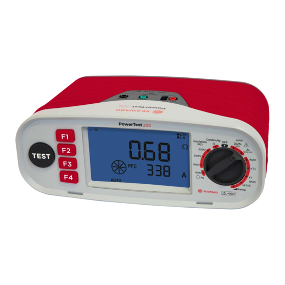
Do not open unit, no other serviceable parts 4. Unit Description The PowerTest 200 is a hand held, multi-function electrical installation test instrument, capable of performing all of the required electrical tests. Tests are selected using the rotary switch. 4.1. Identifying parts of the unit... -
Page 9: Lcd Display
1 3 . Warning Icons. These icons are used to inform the user of the potential of any hazard or warning which may restrict the operation of the PowerTest 200. Details are provided in the relevant parts of these operating instructions. -
Page 10: Using The Powertest 200
The remote probe can be used in place of the standard 4mm red test lead. When the remote probe is connected, the TEST button on the probe performs the same function as the TEST key on the PowerTest 200. Either TEST button can be used to initiate a measurement. -
Page 11: Insulation Resistance Tests
Rotate the rotary switch until the Continuity test is selected. When the continuity test is selected, the PowerTest 200 will display the user selectable test options for approximately 1 second; Buzzer, Lead Zero and Auto Start. If the Buzzer or Lead Zero was previously enabled then the icon will remain on the display when the continuity test is selected. - Page 12 Figure 3 – Insulation Measurement Use the rotary switch to select either the 250V, 500V or 1000V MΩ test. The PowerTest 200 will display the Test Lock and battery symbol for 1 second. If the Test Lock feature is required, it should be activated as described below.
-
Page 13: Voltage Measurement And Phase Rotation
SEAWARD PowerTest 200 USER MANUAL 5.6. Voltage Measurement and Phase Rotation Figure 4 – Voltage measurement using test Figure 5 – Voltage measurement at a mains probes outlet Figure 7 – Phase rotation Figure 6 – Voltage measurement at a distribution board Rotate the rotary switch until the V test is selected. -
Page 14: High Current Earth Loop Impedance / Line Impedance
L2 L3 if the rotation is correct. 5.7. High Current Earth Loop Impedance / Line Impedance The PowerTest 200 will only allow the Earth Loop Impedance test to be performed if the correct voltages are detected between line-earth (L-PE illuminated), line-neutral (L-N illuminated) and neutral-earth (N-PE not illuminated). - Page 15 The PowerTest 200 will determine the fault voltage that may appear on the protective conductor during the test. If the fault voltage is greater than 25V the PowerTest 200 will indicate >25V on the LCD, but the user may proceed with the test. If the fault voltage is greater than 50V, this is indicated on the LCD and the test is inhibited.
-
Page 16: Non Trip Earth Loop Impedance / Line Impedance
When Auto start is activated the AUTO icon is shown on the display. Loop measurements will automatically start approximately 4s after the PowerTest 200 is connected to correct mains supply via a mains plug or the test probes. The Auto Start function remains enabled if the switch position is changed or the PowerTest 200 is powered off. -
Page 17: Auto Rcd Test Sequence
The PowerTest 200 will determine the fault voltage that may appear on the protective conductor during the test. If the fault voltage is greater than 25V the PowerTest 200 will indicate >25V on the LCD, but the user may proceed with the test. If the fault voltage is greater than 50V, this is indicated on the LCD and the test is inhibited. - Page 18 RCD types. Each time the F2 key is pressed the next option is selected. During selective tests the PowerTest 200 will display a delay timer which counts down from 30s to 0s. Pressing the Test key or turning the rotary switch while the PowerTest 200 is counting will terminate the count.
-
Page 19: Rcd Trip Time Tests
The PowerTest 200 will determine the fault voltage that may appear on the protective conductor during the test. If the fault voltage is greater than 25V the PowerTest 200 will indicate >25V on the LCD, but the user may proceed with the test. If the fault voltage is great than 50V, this is indicated on the LCD and the test is inhibited. - Page 20 The PowerTest 200 will determine the fault voltage that may appear on the protective conductor during the test. If the fault voltage is greater than 25V the PowerTest 200 will indicate >25V on the LCD, but the user may proceed with the test. If the fault voltage is great than 50V, this is indicated on the LCD and the test is inhibited.
-
Page 21: Rcd Trip Current (Ramp) Tests
SEAWARD PowerTest 200 USER MANUAL Please note that the PowerTest 200 is not capable of performing all of the different test currents for all of the different manual RCD settings. 10mA 30mA 100mA 300mA 500mA ½I∆N 1I∆N 2I∆N 5I∆N 5.11. RCD Trip Current (Ramp) Tests... -
Page 22: Electrical Specifications
RCD types. Each time the F2 key is pressed the next option is selected. During selective tests the PowerTest 200 will display a delay timer which counts down from 30s to 0s. Pressing the Test key or turning the rotary switch while the PowerTest 200 is counting will terminate the count. -
Page 23: Earth Loop Impedance
SEAWARD PowerTest 200 USER MANUAL 6.3. Earth Loop Impedance Supply Voltage 195 – 253V, 45Hz – 65Hz Nominal Test Current <15mA (non-trip test) 3A (high current test) Display Range 0.01Ω - 2000Ω Measuring Range 0.10Ω - 1999Ω (high current) (EN 61557-3) 1.00Ω... -
Page 24: Voltage/Frequency Measurement
Operating temperature range of 0°C to 40°C, without moisture condensation. The PowerTest 200 can be stored at any temperature in the range -25°C to +65°C (relative humidity up to 90%). The batteries should be taken out of the instrument for storage. -
Page 25: Cleaning
Power the unit off by selecting the Off position on the rotary switch. Disconnect all the test leads from the unit. Position the PowerTest 200 face down and release the 4 captive screws in the battery compartment cover. Remove the battery compartment cover. -
Page 26: Service And Calibration
Power the unit off by selecting the Off position on the rotary switch. Disconnect all the test leads from the unit. Position the PowerTest 200 face down and release the captive 4 screws in the battery compartment cover. Remove the battery compartment cover. - Page 27 SEAWARD PowerTest 200 USER MANUAL Appendix A IEC61557-2: Insulation Intrinsic error or Reference conditions or specified operating range Designation influence quantity code Intrinsic error Reference conditions Position Reference position ±90° Supply voltage At the limits stated by the manufacturer Temperature 0°C and 40°C...
- Page 28 SEAWARD PowerTest 200 USER MANUAL IEC61557-4: Resistance of earth connection and equipotential bonding Intrinsic error or Reference conditions or specified operating range Designation influence quantity code Intrinsic error Reference conditions Position Reference position ±90° Supply voltage At the limits stated by the manufacturer Temperature 0°C and 40°C...
Need help?
Do you have a question about the PowerTest 200 and is the answer not in the manual?
Questions and answers