TE AMP 3K/40 Customer's Manual

TE AMP 3K/40 Customer's Manual

Up 2268 kg crimp force

Advertisement

© 2016 TE Connectivity Ltd. family of companies.
All Rights Reserved.
*Trademark
TE Connectivity, TE connectivity (logo), and TE (logo) are trademarks. Other logos, product, and/or company names may be trademarks of their respective owners.
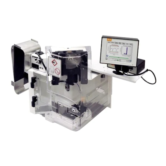
AMP 3K/40* CE Terminating Machines
PN 2161400-[ ] and AMP 5K/40* CE
Terminating Machines PN 2161500-[ ]
SAFETY PRECAUTIONS - AVOID INJURY - READ THIS FIRST! ...................................... 2
1. INTRODUCTION .................................................................................................................. 3
2. DESCRIPTION ..................................................................................................................... 5
2.1.Functional Description .................................................................................................... 5
2.2.Electrical Description ...................................................................................................... 8
2.3.Machine Guard ............................................................................................................... 8
3. RECEIVING INSPECTION AND INSTALLATION ............................................................... 8
3.1.Receiving Inspection ...................................................................................................... 8
3.2.Installation ...................................................................................................................... 9
4. OPERATION ...................................................................................................................... 11
4.1.Control Panel Operation ............................................................................................... 11
4.2.Applicator Installation ................................................................................................... 11
4.3.Setup ............................................................................................................................ 13
4.4.Mode Selection and Operation ..................................................................................... 13
4.5.Adjusting the Motor Speed ........................................................................................... 14
4.6.Crimp Height Adjustment ............................................................................................. 14
4.7.End-Feed/Side-Feed Applicator Conversion ................................................................ 14
5. PREVENTIVE MAINTENANCE ......................................................................................... 14
5.1.Cleaning ....................................................................................................................... 14
5.2.Lubrication .................................................................................................................... 15
6. ADJUSTMENTS ................................................................................................................. 15
6.1.Measuring the Shut Height ........................................................................................... 16
6.2.Shut-Height Adjustment ............................................................................................... 16
6.4.Guard Insert Adjustment .............................................................................................. 18
ASSEMBLY ........................................................................................................................ 19
8. TROUBLESHOOTING ....................................................................................................... 21
8.1.Error Codes .................................................................................................................. 21
8.2.Diagnostics ................................................................................................................... 22
9. SOTWARE VERSION IDENTIFICATION .......................................................................... 22
10. DISPOSAL ......................................................................................................................... 22
11. REPLACEMENT AND REPAIR ......................................................................................... 23
12. RoHS INFORMATION ........................................................................................................ 23
13. REVISION SUMMARY ....................................................................................................... 23
PRODUCT INFORMATION 1-800-522-6752
This controlled document is subject to change.
For latest revision and Regional Customer Service,
visit our website at www.te.com.
Customer Manual
409-10204
16 SEP 16 Rev G
1 of 23

Advertisement

Table of Contents
loading
Need help?

Need help?

Do you have a question about the AMP 3K/40 and is the answer not in the manual?

Questions and answers

Summary of Contents for TE AMP 3K/40

  • Page 1: Table Of Contents

    1 of 23 All Rights Reserved. For latest revision and Regional Customer Service, visit our website at www.te.com. *Trademark TE Connectivity, TE connectivity (logo), and TE (logo) are trademarks. Other logos, product, and/or company names may be trademarks of their respective owners.
  • Page 2: Safety Precautions - Avoid Injury - Read This First

    409-10204 SAFETY PRECAUTIONS — AVOID INJURY — READ THIS FIRST! Safeguards are designed into this application equipment to protect operators and maintenance personnel from most hazards during equipment operation. However, certain safety precautions must be taken by the operator and repair personnel to avoid personal injury, as well as damage to the equipment. For best results, application equipment must be operated in a dry, dust-free environment.
  • Page 3: Introduction

    This manual contains information on operation, preventive maintenance, and adjustments of the AMP 3K/40 and AMP 5K/40 CE Terminating Machines PN 2161400-[ ] and PN 2161500-[ ] respectively. See Figure 1. Descriptions in this manual pertain to the controls and adjustments on the AMP 3K/40 and AMP 5K/40 machines only.
  • Page 4 409-10204 When reading this manual, pay particular attention to DANGER, CAUTION, NOTE statements. DANGER Denotes an imminent hazard which may result in moderate or severe injury. CAUTION Denotes a condition which may result in product or equipment damage. NOTE Highlights special or important information. Always wear approved eye protection while operating the equipment.
  • Page 5: Description

    409-10204 2. DESCRIPTION The AMP 3K/40 and AMP 5K/40 CE terminating Machines were designed to be used as stand-alone semi- automatic bench units. They are assembled with metric hardware. NOTE Measurements are in metric units [followed by U.S. customary units in brackets] unless otherwise indicated. Some commercial items may contain non-metric hardware.
  • Page 6 409-10204 Motor Gearbox Assembly Electrical Control Box Assembly Terminal Strip Guide Mounting Surface for End-Feed Applicators Figure 4 2. The crankshaft-ram group conveys the motor rotational force to the up-and-down action of the ram for driving the applicator during the crimping cycle. 3.
  • Page 7 409-10204 Figure 5 7 of 23 Rev G...
  • Page 8: Electrical Description

    To protect against damage that may have occurred during shipment, remove the machine from the crate (paragraph 3.2.) and carefully inspect the machine for damage. If damage is evident, file a claim against the carrier and notify TE immediately. 8 of 23...
  • Page 9: Installation

    409-10204 3.2. Installation Remove all mounting bolts securing the machine to the shipping pallet. Install lift ring (see Figure 7) on top of the machine. NOTE Lift ring (M1220 eye bolt) is customer supplied. Lift point for the equipment. CAUTION Install the lift ring carefully.
  • Page 10: Considerations Affecting Placement Of Bench Machines (Figure 8)

    409-10204 3.3. Considerations Affecting Placement of Bench Machines (Figure 8) The location of the machine in relation to the operator's position is extremely important in terms of both safety and maximum efficiency. Studies have repeatedly shown that operator fatigue will be reduced, and greater efficiency achieved, if: ...
  • Page 11: Operation

    409-10204 Foot Switch When the operator is correctly positioned in front of a machine equipped with a foot switch, the foot should rest on the switch comfortably. The foot switch should be movable, so that its location can be readily changed when the operator shifts position to minimize fatigue.
  • Page 12 409-10204 Guard Status Speed Indication Machine Status/ Error Code Error Reset Batch Count Count Reset Speed Decrease Main Power Switch Speed Increase Decrease Speed -- Decrease the motor speed for normal cycle operation and for jogging. Increase Speed -- Increase the motor speed for normal cycle operation and for jogging. Error Reset -- Clears the displayed error code.
  • Page 13: Setup

    409-10204 4.3. Setup Install a miniature applicator and terminals according to paragraph 4.2. 1. Turn on the main power using the switch located on the front of the control panel. 2. Be sure the guard is closed. 3. Jog the machine (as described in paragraph 4.3.B.) through a complete crimp cycle. NOTE Machine should be able to jog through the terminal and wire at maximum jog speed to determine crimp capacity.
  • Page 14: Adjusting The Motor Speed

    409-10204 4.5. Adjusting the Motor Speed The speed of the motor is adjusted using the Decrease Speed and Increase Speed buttons on the membrane keypad (see Figure 9). The Decrease and Increase buttons are used to adjust the motor speed for Full-Cycle mode and for Jog mode.
  • Page 15: Lubrication

    Chevron Ultra-Duty EP NLGI 2, Chevron Ulti-Plex EP NLGI 2, and Caltex Ultra-Duty EP NLGI 2. NOTE Contact TE engineering for 2 choice alternates. CAUTION It is important to only use Lithium-based grease with extreme pressure (EP) additives.
  • Page 16: Measuring The Shut Height

    SHUT HEIGHT DIMENSIONS APPLICATOR TYPE 2161400-[ ] 135.79 mm ±0.025 679655-2 TE-Type 2161500-[ ] [5.346 ±.0010 in.] Figure 11 6.2. Shut-Height Adjustment The shut height is pre-set at the factory and should not require further adjustment unless it is necessary to replace parts.
  • Page 17: Crimp Height Adjustment Using Precision Adjustment Mechanism

    409-10204 2. If the shut height is incorrect, proceed as follows: a. Remove the two socket head cap screws which secure the ram post adaptor. Remove the ram post adaptor and shims. Change the shim thickness as required to adjust the shut height. Shims contain .051- mm [.002-in.] peel-type laminations.
  • Page 18: Guard Insert Adjustment

    409-10204 1. Adjust the manual precision adjustment lever to “0" by pulling the lever away from the pivot pin. Lock the lever in place by releasing it. 2. Install the applicator into the machine as described in paragraph 4.2. 3. Cycle the machine to crimp three sample terminations. Check the crimp height of the samples. If the crimp heights are not correct, adjust the crimp height according to Step 4.
  • Page 19: Machine Options And Installation Of The Air Feed Valve Assembly

    409-10204 The guard contains two slots into which the inserts can be placed: the rear slot places the insert close to the applicator; the front slot places the insert farther away from the applicator. The type of insert used determines which slot is to be used.
  • Page 20 409-10204 8. Tighten gland nut "snugly" around wire. 9. Secure cover to the electrical control box with six M4 bolts. 10. For metric air line fittings, remove Item 1. For English air line fittings, Item 1 remains. 11. If the air feed applicator requires the optional base plate clamp: a.
  • Page 21: Troubleshooting

    409-10204 Four-Way Solenoid Valve Air Feed Cable Mounting Screws Valve Lockout Side Valve Large Washer Filter Figure 16 8. TROUBLESHOOTING Contact the Support Center at 1-800-522-6752. 8.1. Error Codes See the table in Figure 17 for a listing of error codes. ERROR CODE ERROR DESCRIPTION E001...
  • Page 22: Diagnostics

    When the display on the control panel turns on, the control panel software version will be displayed briefly, followed by the CPU motor controller software version. Both versions follow the format “X.XX.XX.” 10. DISPOSAL Contact TE for disposal. 22 of 23 Rev G...
  • Page 23: Replacement And Repair

    13. REVISION SUMMARY   Updated to most current TE logo (header/footers) Changed para 4.7. Note from Lubricator Bowl Assembly PN 354550-1 to -3, and added “When using an Ocean Side-Feed or End-Feed applicator, the lubricator assembly part numbers are 2119955-1 and ...

This manual is also suitable for:

Amp 5k/40Amp 3k/40 ceAmp 5k/40 ce

Table of Contents

Save PDF