Table of Contents
Advertisement
Advertisement
Table of Contents
Troubleshooting

Related Manuals for Furuno 1815


Summary of Contents for Furuno 1815
- Page 1 OPERATOR'S MANUAL MARINE RADAR MODEL 1815 www.furuno.com...
- Page 2 How to discard a used battery Some FURUNO products have a battery(ies). To see if your product has a battery, see the chap- ter on Maintenance. Follow the instructions below if a battery is used. Tape the + and - terminals of battery before disposal to prevent fire, heat generation caused by short circuit.
- Page 3 SAFETY INSTRUCTIONS Read these safety instructions before you operate or install the equipment. Indicates a condition that can cause death or serious WARNING injury if not avoided. Indicates a condition that can cause minor or moderate CAUTION injury if not avoided. Warning, Caution Mandatory Action Prohibitive Action...
- Page 4 SAFETY INSTRUCTIONS CAUTION CAUTION WARNING Usethe correct fuse. The guard zone alarm is an effective aid to anti-collison. Use of a wrong fuse can result in fire or damage to the equipment. Its use does not relieve the operator of the responsibility to keep a vigilant watch on Do not place liquid-filled containers his or her surroundings.
- Page 5 SAFETY INSTRUCTIONS Warning Label(s) Warning label(s) is(are) attached to the equipment. Do not remove the label(s). If a label is missing or damaged, contact a FURUNO agent or dealer about replacement. Name: Warning Label 1 WARNING Type: 86-003-1011-1 To avoid electrical shock, do not Code No.: 100-236-233-10...
-
Page 6: Table Of Contents
TABLE OF CONTENTS FOREWORD ......................... viii SYSTEM CONFIGURATION ................... x INSTALLATION .....................1-1 1.1 Equipment List......................1-1 1.2 How to Install the Display Unit..................1-1 1.3 How to Install the Antenna Unit ..................1-3 WIRING ........................2-1 2.1 Wiring .........................2-1 INITIAL SETTINGS ....................3-1 3.1 How to Select Language ....................3-1 3.2 How to Select Radar Purpose ..................3-2 3.3 Initial Settings ......................3-2 OPTIONAL EQUIPMENT ..................4-1... - Page 7 TABLE OF CONTENTS 5.19 How to Off-center the Display .................. 5-24 5.19.1 How to select the off-center mode ............... 5-24 5.19.2 Off-center the display ................... 5-25 5.20 Zoom ........................5-26 5.20.1 Zoom mode ....................5-26 5.20.2 How to zoom ....................5-27 5.21 Echo Stretch......................
- Page 8 TABLE OF CONTENTS 6.3 SART (Search and Rescue Transponder)..............6-6 6.3.1 SART description ...................6-6 6.3.2 General remarks on receiving SART..............6-7 6.4 RACON........................6-8 TT OPERATION.....................7-1 7.1 Precautions for Use ....................7-1 7.2 Controls for Use with TT.....................7-1 7.3 TT Display On/Off.......................7-2 7.4 How to Acquire and Track the Targets ...............7-2 7.4.1 Manual acquisition..................7-2 7.4.2...
- Page 9 TABLE OF CONTENTS 10.3 Magnetron Life ......................10-3 10.4 Simple Troubleshooting ................... 10-4 10.5 Advanced-level Troubleshooting................10-5 10.6 Diagnostic Test ......................10-7 10.7 LCD Test ........................10-9 10.8 Radar Sensor Test ....................10-10 APPENDIX 1 MENU TREE ..................AP-1 APPENDIX 2 GEODETIC CHART LIST ..............AP-5 APPENDIX 3 DIGITAL INTERFACE.................AP-7 APPENDIX 4 JIS CABLE GUIDE ................AP-14 SPECIFICATIONS .....................SP-1...
-
Page 10: Foreword
We would appreciate feedback from you, the end-user, about whether we are achieving our pur- poses. Thank you for considering and purchasing FURUNO equipment. Features The main features are as shown below. • The main specifications of the MODEL 1815 are outlined in the table below. Antenna unit size Model Output Range... - Page 11 FOREWORD Radar function availability The Model 1815 is available in two types, [River] (river use) and [Sea] (sea use). Some functions may not available depending on the type selected See the table below for item and availability. Type and function availability...
-
Page 12: System Configuration
SYSTEM CONFIGURATION Basic configuration is shown below with solid line. MODEL 1815 Antenna Unit RSB-127-120 RTR-120 Power cable 1.4 m Equipment category Antenna Unit: Exposed to the weather Other Equipment : Protected from the weather Antenna cable (FRU-CF-FF-XXM) (10/15/20 m) - Page 13 SYSTEM CONFIGURATION This page is intentionally left blank.
-
Page 14: Installation
INSTALLATION Equipment List Name Type Code No. Remarks Display Unit RDP-157 — Antenna Unit RTR-120 — Mounting Base RTR-120 — Installation Materials CP03-37600 000-033-122 Select CP03-37610 000-033-123 CP03-37620 000-033-124 Radome Mounting Bracket OP03-209 001-078-350 Option External Buzzer OP03-21 000-030-097 Option NMEA Data Converter IF-NMEA2K2 000-020-510... - Page 15 1. INSTALLATION 1. Fix the bracket assembly to a desktop with four self-tapping screws (525, sup- plied). Be sure to follow the recommended maintenance space show in the outline drawing. Insufficient space may damage to the connectors when disconnecting and reconnecting them. 2.
-
Page 16: How To Install The Antenna Unit
1. INSTALLATION How to Install the Antenna Unit Select a mounting location for the antenna unit considering the following points. • Install the unit on a common mast, radar mast. etc. • Install the antenna unit on a solid location, for example radar arch or on a mast on a platform. - Page 17 1. INSTALLATION • Keep the unit away from smoke and exhaust stacks. Hot air affects antenna per- formance. Hot air can also damage the unit. The temperature at the mounting lo- cation should not exceed 55°C(131°F) Tools and materials for mounting Name Usage Drill holes for mounting.
- Page 18 1. INSTALLATION 1. From the bottom of the radome, remove spring washers (M10), flat washers (M10) and hex head bolts (M1025). Flat washer Spring washer ×4 Hex head bolt (M10×20) 2. Use the mounting template (supplied) to mark the location of fixing holes in the mounting platform.
- Page 19 1. INSTALLATION How to connect the power cable Observe the following guidelines for connecting the power cable. • The connectors must not strike any part of the vessel by wind, etc. • The load applied to the connectors must not be more than their own weight. •...
- Page 20 1. INSTALLATION How to assemble the bracket: 1. Fasten the fixing plates to brackets (1) and (2) with four M820 hex bolts. 2. Fit brackets (1) and (2) loosely with support plates (1) and (2) using four M412 hex bolts, so that the gap between the brackets can be adjusted. 3.
- Page 21 1. INSTALLATION This page is intentionally left blank.
-
Page 22: Wiring
WIRING Wiring Use the supplied cable FRU-CF-F01 to connect a satellite compass, heading sensor, GPS navigator, external buzzer, and power supply to the 12-24 VDC/NMEA connec- tor. Connect the antenna cable (FU-CF-xxM (10m/15m/20m/30m) to the antenna port. See the interconnection diagram at the back of this manual for details. Leave slack in the cable to ease maintenance. - Page 23 2. WIRING Connector Color Remarks DC-P-IN(+) Power input, 12-24 VDC DC-M-IN(-) TD1-A GRN/BLK(1) IEC61162-2/NMEA1 TD1-B GRN/RED(1) RD1-H GRY/BLK(1) RD1-C GRY/RED(1) TD2-A GRN/BLK(2) IEC61162-2/NMEA2 TD2-B GRN/RED(2) RD2-H GRY/BLK(2) RD2-C GRY/RED(2) RD3-H GRY/BLK(3) IEC61162-2/NMEA3 RD3-C GRY/RED(3) 12V-P(+) Power output, 12-24 VDC 12V-M(-) EXT-BUZZ-EN External buzzer SHIELD...
-
Page 24: Initial Settings
INITIAL SETTINGS How to Select Language Do the following to select the language to use. 1. Press the ( ) key on the display unit to turn on the power. 2. Press the MENU/ESC key to show the menu. 3. Press , on the Cursorpad to select [Factory], then press the ENTER key.The cursor moves to the menu item section and [Language] is selected. -
Page 25: How To Select Radar Purpose
3. INITIAL SETTINGS How to Select Radar Purpose 1. Press the MENU/ESC key to show the menu. 2. Press , on the Cursorpad to select [Factory], then press the ENTER key. 3. Press , on the Cursorpad to select [Usage], then press the ENTER key. 4. - Page 26 3. INITIAL SETTINGS Item description • [Simulation]: Normally, set to [Off.] To view the demonstration picture, select [On]. • [Antenna Rotation]: Select [Rotate] to rotate the antenna and transmit radar puls- es. The [Stop] setting, which transmits radar pulses without rotating the antenna, is for use by the service technician.
- Page 27 3. INITIAL SETTINGS • [Main Bang Suppression]: Reduce the main bang (black hole at center of screen), which appears at the display center on short ranges, as follows. 1. Transmit on the shortest range. 2. Open the [Installation] menu and select [MBS Adjust]. 3.
-
Page 28: Optional Equipment
OPTIONAL EQUIPMENT External Buzzer The external buzzer alerts you to violation of the guard zone in a remote location. Con- nect the buzzer to the display unit as shown below, using the external buzzer installa- tion kit. DISPLAY UNIT 12 V Power RDP-157 Connection port... - Page 29 4. OPTIONAL EQUIPMENT Terminal Board (local supply) TD1_A TD1_B RD1_H RD1_C TD2_A TD2_B RD2_H RD2_C EXTERNAL BUZZER RD3_H RD3_C 12V_P 12V_M EXT_BUZZ_EN...
-
Page 30: Operation
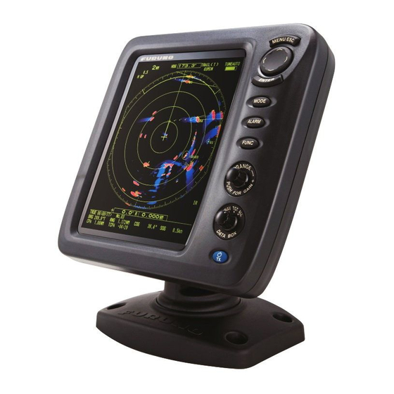
OPERATION Controls Display unit The display unit has six keys, two knob controls and a Cursorpad that control the ra- dar. When you correctly do an operation, the unit beeps one time. If the operation is incorrect, the unit beeps three times. Control Description MENU/ESC... -
Page 31: How To Turn The Radar On/Off And Transmit
5. OPERATION How to Turn the Radar On/Off and Transmit Press the key to turn on the radar. To turn off the radar, press and hold down the key until the screen turns off. Start-up screen When you turn on the power, the initialization screen appears followed by the start-up screen. -
Page 32: Display Indications
5. OPERATION Display Indications Offcenter (M: Manual, A: Auto, C: Custom) Trail reference Heading Trail time North marker 3 5 0 . 0 ° Range TRAIL(T) TUNEAUTO H D G Tuning indicator 15 S Range ring interval OFFCENT(A) ALM1_IN Target Alarm 1 (2) Display mode H UP ALM2_IN... -
Page 33: How To Adjust Display Brilliance, Panel Dimmer
4. Press the MENU/ESC key to close the window. Menu Description This MODEL 1815 series has 14 menus and 7 sub menus. Below is the basic proce- dure for menu operation. 1. Press the MENU/ESC key to open the menu. - Page 34 5. OPERATION 2. Use the Cursorpad ( or ) to select a menu or a sub menu. The cursor (yellow) in the Menu column indicates the menu currently selected. The menu items in the right window change according to the menu selected. Menu description [Brill/Color]: Adjust the brilliance and color.
-
Page 35: Tuning
5. OPERATION Tuning In default, the radar receiver can be tuned automatically after turning the radar to TX. If you require fine tuning in manual, do the following: 1. Transmit the radar and select the maximum range with the RANGE knob. 2. -
Page 36: Display Modes
5. OPERATION Display Modes This radar has the display modes shown below. All modes except head-up require a heading signal. The true motion mode additionally requires position data. Relative Motion (RM) • [Head Up] (H UP) • [Course Up] (C UP) •... -
Page 37: Description Of Display Modes
5. OPERATION Note 2: All modes except head-up require a heading signal in AD-10 format or NMEA format. If the heading signal is lost, the mode is changed to head-up and the north marker disappears. The display for heading is XXX.X and the alarm sounds. The mes- sage "GYRO"... - Page 38 5. OPERATION North marker True motion mode Heading line Your ship and other objects in motion move with their true courses and speed. All fixed tar- gets, like landmasses, appear as fixed echoes in ground stabilized TM. When your ship reaches a point that is 75% of the radius of the display, the position is reset.
-
Page 39: How To Select The Range Scale
5. OPERATION How to Select the Range Scale The selected range scale, range ring interval and pulse length are shown at the top left corner on the screen. When an objective target comes closer, reduce the range scale so that a target appears in 50-90% of the display radius. Rotate the RANGE knob to select range, clockwise to increase the range, or counter- clockwise to decrease the range. -
Page 40: How To Reduce The Sea Clutter
5. OPERATION 5.10 How to Reduce the Sea Clutter The reflected echoes from the waves appear around your ship and have the name "sea clutter". The sea clutter extends according to the height of waves and antenna above the water. When the sea clutter hides the targets, use the sea clutter function to reduce the clutter, either manually or automatically. -
Page 41: How To Reduce The Rain Clutter
5. OPERATION Sea clutter at Sea clutter properly adjusted; screen center sea clutter reduced Sea clutter 2. Press the MENU/ESC key to close the window. 5.11 How to Reduce the Rain Clutter The reflections from the rain or snow appear on the screen. These reflections have the name "rain clutter". -
Page 42: Cursor
5. OPERATION 5.12 Cursor The cursor functions to find the range and bearing (default function) to a target or the latitude and longitude position of a target. Use the Cursorpad to position the cursor and read the cursor data at the screen bottom. Cursor 110.1°... -
Page 43: Interference Rejector
5. OPERATION 3. Use the Cursorpad ( or ) to select [Cursor Data] and press the ENTER key. Cursor Position options 4. Use the Cursorpad ( or ) to select [Rng/Brg] or [Lat/Lon] then press the EN- TER key. (When the navigation data is displayed, cursor latitude and longitude po- sition cannot be displayed.) 5. -
Page 44: Noise Rejector
5. OPERATION 5.14 Noise Rejector White noise can appear on the screen as random "marks". You can reduce this noise as follows: 1. Press the MENU/ESC key to open the menu. 2. Use the Cursorpad ( or ) to select [Echo] and press the ENTER key. 3. -
Page 45: How To Measure The Range With A Vrm
5. OPERATION 3. Use the Cursorpad ( or ) to select [Rings Brill] and press the ENTER key. 4. Use the Cursorpad ( or ) to select an option and press the ENTER key. [4] is the brightest. [Off] turns off the range rings. 5. -
Page 46: How To Select Vrm Unit
5. OPERATION 5.15.3 How to select VRM unit You can select the unit of measurement used by the VRM. The selections are nautical miles (NM), kilometers (KM), statute miles (SM) or kiloyard (KYD). The cursor range unit is also changed when the VRM unit is changed. 1. -
Page 47: How To Measure The Bearing To A Target
5. OPERATION 5.16 How to Measure the Bearing to a Target Use the Electronic Bearing Line (EBL) to take a bearing of a target. There are two EBLs, No. 1 and No. 2. Each EBL is a straight dashed line from the center of the screen to the edge. -
Page 48: Ebl Reference
5. OPERATION 5.16.2 EBL reference "R" (relative) follows the EBL indication if the bearing is relative to the heading of your ship. "T" (true) follows the EBL indication if the bearing is in reference to the north. You can select relative or true in the head-up and true view modes. The bearing indication is true in all other modes. -
Page 49: How To Measure The Range And Bearing Between Two Targets
5. OPERATION 5.17 How to Measure the Range and Bearing Between Two Targets You can move the origin of the EBL to measure the range and bearing between two targets. 1. Press the MODE key. 2. Select [EBL], followed by [EBL 1], then press the ENTER key. 3. -
Page 50: Target Alarm
5. OPERATION 5.18 Target Alarm The target alarm looks for targets (ship, landmass, etc.) in the area CAUTION CAUTION you set. Audiovisual alarms are Do not depend on the alarm as the released when a target enters (or only means to detect possible exits) the alarm area. -
Page 51: How To Stop The Audio Alarm
5. OPERATION 5.18.2 How to stop the audio alarm When a target enters (or exits) the target alarm zone, the target flashes and the alarm sounds. The alarm message appears at the bottom of the screen. To stop the audio alarm, press any key. -
Page 52: How To Sleep A Target Alarm Temporarily
5. OPERATION 5.18.4 How to sleep a target alarm temporarily When you do not require a target alarm temporarily, you can sleep the target alarm. The alarm zone remains on the screen, but any targets that enter (or exit) the alarm zone do not trigger the audio and visual alarms. -
Page 53: How To Off-Center The Display
5. OPERATION 3. Use the Cursorpad ( or ) to select [Panel Buzzer] (or [External Buzzer] for op- tional buzzer) and press the ENTER key. Panel Buzzer and External Buzzer options 4. Use the Cursorpad ( or ) to select [On] or [Off] then press the ENTER key. 5. -
Page 54: Off-Center The Display
5. OPERATION 5.19.2 Off-center the display The mode selected from the menu appears at top left corner of the display, when the off-center feature is activated - "OFFCENT(M)" (Manual), "OFFCENT(C)" (Custom) or "OFFCENT(A)" (Auto). Manual (Indication: "OFFCENT(M)") You can move your ship position to the current cursor position on all modes except true motion, within 75% of the available display area. -
Page 55: Zoom
5. OPERATION 5.20 Zoom The zoom function expands the length and width of a selected target as much as twice its normal size, in the zoom window. You select the target to zoom with the zoom cur- sor. The selected target is zoomed in the zoom window. TT and AIS symbols can be displayed in the zoom window, but are not zoomed. -
Page 56: How To Zoom
5. OPERATION 5.20.2 How to zoom Relative or True zoom mode 1. Use the Cursorpad to put the cursor on the position desired. 2. Press the MENU/ESC key to open the menu. 3. Use the Cursorpad ( or ) to select [Display] and press the ENTER key. 4. - Page 57 5. OPERATION Target zoom mode The TT or AIS target as below can be displayed in the zoom window: TT: The symbol is enlarged twice its normal size. AIS: The symbol is enclosed in a broken square. (The symbol is not enlarged.) The zoom cursor moves with the TT or AIS target.
-
Page 58: Echo Stretch
5. OPERATION 5.21 Echo Stretch The echo stretch feature enlarges the targets in the range and bearing directions to make the targets easier to see. This feature is available on any range. There are three levels of echo stretch, [1], [2] and [3]. [3] enlarges the targets the most. Note: The echo stretch magnifies the targets, sea and rain clutters, and radar interfer- ence. -
Page 59: Trail Mode
5. OPERATION 5.22.2 Trail mode You can display the echo trails in true or relative motion. True mode The true trails show true target movements according to their over-the-ground speeds and courses. The stationary targets do not show the trails. The true trails require a heading signal and position data. -
Page 60: Trail Gradation
5. OPERATION 5.22.3 Trail gradation Trails can be shown in single or multiple gradation. Multiple gradation fades the gra- dation over time. 1. Press the MENU key to open the menu. 2. Use the Cursorpad ( or ) to select [Target Trails] and press the ENTER key. 3. -
Page 61: Trail Level
5. OPERATION 5.22.5 Trail level You can select which target strength to display. 1. Press the MENU/ESC key to open the menu. 2. Use the Cursorpad ( or ) to select [Target Trails] and press the ENTER key. 3. Use the Cursorpad ( or ) to select [Level] and press the ENTER key. Level options 4. -
Page 62: Narrow Trails
5. OPERATION Note: If the newly selected range is less than or equal to 1/4 of the previous range, trails are erased. If the newly selected range is longer than the previous range, the previous trails are left to be displayed. 5. -
Page 63: How To Program The Func Key
5. OPERATION 5.23 How to Program the FUNC Key The FUNC key can be programmed to do the function you assign. Function key operation Press the FUNC key to do the function assigned to the key. Press the key successive- ly to change the setting. -
Page 64: Wiper
5. OPERATION 3. Use the Cursorpad ( or ) to select [Echo Average] and press the ENTER key. Echo Average options 4. Use the Cursorpad ( or ) to select an echo averaging option and press the EN- TER key. [Off]: Deactivate the echo average. -
Page 65: Characteristics Curve
5. OPERATION 5.26 Characteristics Curve You can change the characteristics curve to reduce unwanted weak echoes (sea re- flections, etc.). Select [1], [2] or [3] depending on conditions when unwanted weak echoes hide wanted targets. 1. Press the MENU/ESC key to open the menu. 2. -
Page 66: How To Show The Barge Marker
5. OPERATION 5. Use the Cursorpad to select [OS Length] then press the ENTER key. 6. Use the Cursorpad to set the length of own ship then press the ENTER key. 7. Use the Cursorpad to select [OS Width] then press the ENTER key. 8. -
Page 67: Watchman
5. OPERATION 10. Use the Cursorpad to select [Barge Arrangement], then press the ENTER key. 11. The cursor is selecting [Column1(PORT)]. Press the ENTER key. 12. Use the Cursorpad to set the number of barges in the port column. 13. Set other columns similar to how you did in steps 11 and 12. 14. -
Page 68: Alarm Message
5. OPERATION 1. Press the MENU/ESC key to open the menu. 2. Use the Cursorpad ( or ) to select [Alarm] and press the ENTER key. 3. Use the Cursorpad ( or ) to select [Watchman] and press the ENTER key. Watchman options 4. - Page 69 5. OPERATION Alarm category Meaning POSITION NMEA format position data lost NMEA_HDG NMEA format heading signal lost TARGET ALARM1(2) An echo has entered a target alarm zone. An echo has exited a target alarm zone. TT ALARM COLLISION CPA and TCPA of an TT target is less than CPA and TCPA alarm settings.
-
Page 70: Color Selections
5. OPERATION 5.30 Color Selections 5.30.1 Preset colors This radar is preset with color combinations that provide best viewing in daytime, nighttime and twilight. Below are the default color settings for each display item and display color setting. Display item, color design and color Display item Night Twilight... -
Page 71: Echo Area
5. OPERATION 5. Use the Cursorpad ( or ) to select [Background Color] and press the ENTER key. Background Color options 6. Use the Cursorpad ( or ) to select a background color and press the ENTER key. 7. Use the Cursorpad ( or ) to select [Character Color] and press the ENTER key. -
Page 72: Initial Sub Menu
5. OPERATION 4. Use the Cursorpad ( or ) to select [Normal] or [Full Screen] then press the EN- TER key. 5. Press the MENU/ESC key to close the menu. 5.32 Initial Sub Menu The [Initial] sub menu in the [System] menu contains the items which allow you to cus- tomize your radar to meet your needs. - Page 73 5. OPERATION NM (nautical miles) KM (kilometers) SM (statute miles) [Wind Direction]: Wind direction is shown as [Apparent] or [True]. [NMEA Port 1]: Set the baud rate of the equipment connected to Port 1 ([Auto], [4800], or [38400] (bps)). [Auto] provides automatic detection of baud rate from 4800, 9600, 19200 or 38400 (bps).
-
Page 74: Sector Blank
5. OPERATION 5.33 Sector Blank You must prevent the transmission in some areas to protect passengers and crew from microwave radiation. Also, if the reflections of echoes from the mast appear on the screen, you must prevent the transmission in that area. You can set two sectors. 1. -
Page 75: Other Menu Items
5. OPERATION Area of no End bearing transmission Start bearing of sector of sector Sector blank 5.34 Other Menu Items This section describes the menu items not previously described. 5.34.1 Brill/Color menu [View Position]: You can select the angle from where you see the screen. View Position options [Menu Transparency]: You can select the degree of transparency of the menu win- dow so the menu window does not hide the echo display. - Page 76 5. OPERATION [Custom Echo Color]: You can customize the echo color with the following two meth- ods. This function is not available in the [IEC] or [Russian-River] mode. Custom Echo Color setting window Method 1: 1) Select the echo rank to change on the [Rank] (setting range: 1 - 31). 2) Set the RGB values for selected echo rank on the [Red], [Green] and [Blue] (setting range: 0 - 63).
-
Page 77: Display Menu
5. OPERATION 5.34.2 Display menu [Base Text Display]: You can select on/off for the text indications of the following items on the display. The settings on this function are used when you set [Echo Area] to [Full Screen] on the [Display] menu. This function is not available in the [IEC] or [Russian-River] mode. -
Page 78: Units Menu
5. OPERATION 5.34.4 Units menu You can select the unit of measurement for range, ship speed, depth, temperature and wind speed on the [Units] sub menu in the [System] menu. You can not open this sub menu in normal operation. To open this menu, select [Units], hold the MENU/ESC key and press the ALARM key five times. -
Page 79: Navigation Data
5. OPERATION 5.35 Navigation Data 5.35.1 Navigation data during standby The navigation data is shown in standby when [STBY Display] on the [Display] menu is set to [Nav]. Appropriate sensors are required to display the data. Standby indication Speed Trip Depth Water temperature Wind speed... - Page 80 5. OPERATION To show or hide the navigation data at the bottom of the screen, do the following: 1. Press the MENU/ESC key to open the menu. 2. Use the Cursorpad ( or ) to select [Display] and press the ENTER key. 3.
-
Page 81: Waypoint Marker
5. OPERATION 5.36 Waypoint Marker The waypoint marker shows the location of the destination waypoint set on a naviga- tion plotter. The heading signal or course data are required. You can turn on/off the waypoint marker as follows: Waypoint marker Waypoint marker 1. -
Page 82: How To Send The Target Position And Enter The Origin Mark
5. OPERATION 5.37 How to Send the Target Position and Enter the Origin Mark The TLL key functions to send the cursor position to a chart plotter and put an origin mark ( ) at the cursor position on the radar. Use the Cursorpad to put the cursor on a target. - Page 83 5. OPERATION This page is intentionally left blank. 5-54...
-
Page 84: How To Interpret The Radar Display
HOW TO INTERPRET THE RA- DAR DISPLAY General 6.1.1 Minimum and maximum ranges Minimum range The minimum range is defined by the shortest distance at which, using a scale of 0.0625 or 0.125 nm, a target having an echoing area of 10 m is shown separate from the point representing the antenna position. -
Page 85: Radar Resolution
6. HOW TO INTERPRET THE RADAR DISPLAY 6.1.2 Radar resolution The bearing resolution and range resolution are important in radar resolution. Bearing resolution The bearing resolution is the ability of the radar to display the echoes received from two targets at the same range as the separate echoes. The bearing resolution is pro- portional to the antenna length and the wavelength. -
Page 86: Bearing Accuracy
6. HOW TO INTERPRET THE RADAR DISPLAY 6.1.3 Bearing accuracy One of the most important features of the radar is how accurately the bearing of a tar- get can be measured. The accuracy of bearing measurement depends on the narrow- ness of the radar beam. -
Page 87: Sidelobe Echoes
6. HOW TO INTERPRET THE RADAR DISPLAY 6.2.2 Sidelobe echoes When the radar pulse is transmitted, some radiation escapes on each side of the beam, called "sidelobes". If a target is where a target can be detected by the sidelobes as well as the mainlobe, the side echoes can be shown on both sides of the true echo at the same range. -
Page 88: Shadow Sector
6. HOW TO INTERPRET THE RADAR DISPLAY 6.2.4 Shadow sector Funnels, stacks, masts, or derricks near the antenna interrupt the radar beam, and a non-detecting sector can occur. Targets can not be detected within this sector. Wharf and its echo Radar position Wharf and its echo Radar position... -
Page 89: Sart (Search And Rescue Transponder)
6. HOW TO INTERPRET THE RADAR DISPLAY SART (Search and Rescue Transponder) 6.3.1 SART description When any X-band radar reaches within a range of approximately 8 nm, a Search and Rescue Transponder (SART) sends a response to the radar signal. The transmitter signal of response is 12-sweeps signal between 9,500 MHz to 9,200 MHz. -
Page 90: General Remarks On Receiving Sart
6. HOW TO INTERPRET THE RADAR DISPLAY 6.3.2 General remarks on receiving SART SART range errors When the SART is at a range greater than approximately 1 nm, the first dot is dis- played at 0.64 nm beyond the true position of the SART. When the range closes so that the fast sweep responses are seen also, the first range echoes are displayed at 150 m beyond the true position. -
Page 91: Racon
6. HOW TO INTERPRET THE RADAR DISPLAY RACON A RACON is a radar beacon which emits radar-receivable signals in the radar frequen- cy spectrum (X- or S-band). There are several signal formats; in general, the RACON signal appears on the radar screen as a rectangular echo originating at a point just beyond the position of the radar beacon. -
Page 92: Tt Operation
TT OPERATION The TT (Tracked Target) feature manually or automatically acquires and tracks ten targets. Once a target is acquired, a target is automatically tracked within 0.1 to 16 nm. Precautions for Use CAUTION CAUTION CAUTION CAUTION Do not depend on one navigation The plotting accuracy and response of device this TT meets IMO standards. -
Page 93: Tt Display On/Off
7. TT OPERATION TT Display On/Off You can turn the TT display on or off. The system continuously tracks TT regardless of this setting. 1. Press the MENU/ESC key to open the menu. 2. Use the Cursorpad ( or ) to select [TT] and press the ENTER key. 3. -
Page 94: Automatic Acquisition
7. TT OPERATION 7.4.2 Automatic acquisition When you set an automatic acquisition area, the TT can acquire up to five targets au- tomatically. The automatic acquisition area is 2.0 to 2.5 nm in range and ±45° on either side of the heading line in bearing. -
Page 95: Vector Attributes
7. TT OPERATION 3. Use the Cursorpad ( or ) to select [All Cancel] and press the ENTER key. All Cancel options 4. Use the Cursorpad () to select [Yes] and press the ENTER key. All symbols are erased from the screen and the long beep sounds. 5. -
Page 96: Vector Of Your Ship
7. TT OPERATION 3. Use the Cursorpad ( or ) to select [Vector Time] and press the ENTER key. Vector Time setting window 4. Use the Cursorpad ( or ) to select time and press the ENTER key. 5. Use the Cursorpad ( or ) to select [Vector Reference] and press the ENTER key. -
Page 97: Past Position Display (Target Past Position)
7. TT OPERATION Own ship vector Cursor Data box Past Position Display (target past position) This radar can display time-spaced dots (maximum ten dots) that mark the past posi- tions of any TT. You can evaluate actions of a target by the spacing between dots. Be- low are examples of dot spacing and target movement. -
Page 98: Tt Data
7. TT OPERATION 6. Use the Cursorpad ( or ) to select [Past Posn Interval] and press the ENTER key. Past position interval options 7. Use the Cursorpad ( or ) to select the time interval and press the ENTER key. 8. -
Page 99: Cpa/Tcpa Alarm
7. TT OPERATION CPA/TCPA Alarm Set CPA (Closest Point of Approach) alarm range and TCPA (predicted Time to CPA) alarm time to alert you to targets that can be on a collision course. When CPA and TCPA of any TT become less than the preset CPA and TCPA alarm settings, the audio alarm sounds. -
Page 100: Proximity Alarm
7. TT OPERATION 5. Use the Cursorpad ( or ) to select [TCPA] and press the ENTER key. TCPA options 6. Use the Cursorpad ( or ) to select TCPA and press the ENTER key. 7. Press the MENU/ESC key to close the menu. 7.10 Proximity Alarm The proximity alarm alerts you when a TT is within the range you set. -
Page 101: Lost Target
7. TT OPERATION 7.11 Lost Target When the system detects a lost TT, the audio alarm sounds and the alarm message "LOST" appears. The target symbol becomes a flashing square like the following illus- tration. When the system detects the target again, the target symbol becomes a nor- mal symbol. -
Page 102: Ais Operation
AIS OPERATION Connected to the FURUNO AIS Transponders FA-150, FA-100, FA-50 or the AIS Re- ceiver FA-30, the MODEL 1815 can show the name, position and other navigation data of the nearest 100 AIS transponder-equipped ships. This radar accepts position data fixed by WGS-84 geodetic datum. Set the datum to WGS-84 on the GPS navigator connected to this radar. -
Page 103: Ais Symbols
8. AIS OPERATION 3. Use the Cursorpad ( or ) to select [Display] and press the ENTER key. AIS-Display options 4. Use the Cursorpad ( or ) to select [Off] or [On] then press the ENTER key. 5. Press the MENU/ESC key to close the menu. AIS Symbols When the AIS is turned on, AIS targets are displayed with AIS symbol as below. -
Page 104: Ais Target Data
8. AIS OPERATION When there are many activated targets on the screen, you can not easily distinguish the activated targets from the radar images or TT. You can sleep an activated target for easy view of radar images. Sleeping target To activate a target: Put the cursor on the target and press the ENTER key. -
Page 105: How To Sort Targets
8. AIS OPERATION How to Sort Targets You can sort the AIS targets received from the AIS transponder by range from your ship, by sector, by CPA or TCPA. 1. Press the MENU/ESC key to open the menu. 2. Use the Cursorpad ( or ) to select [AIS] and press the ENTER key. 3. -
Page 106: How To Display The Targets Within A Specific Sector
8. AIS OPERATION How to Display the Targets within a Specific Sec- You can display AIS targets only within a specific sector. If the target sorting method is selected to [Sector], the target data within the sector set here is transmitted to this radar. -
Page 107: Vector Attributes
8. AIS OPERATION 4. Use the Cursorpad ( or ) to select the number of targets to display and press the ENTER key. 5. Press he MENU/ESC key to close the menu. Vector Attributes 8.9.1 What is a vector? A vector is a line extending from a tracked target. A vector shows speed and course of the target. -
Page 108: Past Position Display (Target Past Position)
8. AIS OPERATION 8.10 Past Position Display (target past position) This radar can display time-spaced dots (maximum ten dots) that marks the past po- sitions of any tracked AIS target. You can evaluate actions of a target by the spacing between dots. -
Page 109: Cpa/Tcpa Alarm
8. AIS OPERATION 8.11 CPA/TCPA Alarm Set CPA (Closest Point of Approach) alarm range and TCPA (predicted Time to CPA) alarm time to alert you to targets that can be on a collision course. When CPA and TCPA of any AIS target (including a sleeping target) become less than the preset CPA and TCPA alarm settings, the audio alarm sounds. -
Page 110: Proximity Alarm
8. AIS OPERATION 8.12 Proximity Alarm The proximity alarm alerts you when an AIS target is within the range you set. The au- dio alarm sounds and the alarm message "PROXIMITY" appears. The target symbol changes to a dangerous target symbol (red) and flashes with its vector. Press any key to stop the audio alarm and flashing. -
Page 111: Symbol Color
8. AIS OPERATION 4. Use the Cursorpad () to select [Yes] and press the ENTER key. All lost targets symbols are erased from the screen and the long beep sounds. 5. Press the MENU/ESC key to close the menu. 8.14 Symbol Color You can select the AIS symbol color among Green, Red (unavailable in the [IEC] or [Russian-River] purpose), Blue, White or Black. -
Page 112: Gps Operation
GPS OPERATION If the FURUNO GPS Navigator GP-320B is connected to this radar, you can set GP- 320B from this radar. Navigator Mode 1. Press the MENU/ESC key to open the menu. 2. Use the Cursorpad ( or ) to select [GPS] and press the ENTER key. -
Page 113: Datum
9. GPS OPERATION Datum Select the type of datum which matches the paper charts you use for navigation. Se- lect [WGS-84] if the radar is connected to an AIS Transponder. 1. Press he MENU/ESC key to open the menu. 2. Use the Cursorpad ( or ) to select [GPS] and press the ENTER key. 3. -
Page 114: Waas Setup
9. GPS OPERATION WAAS Setup Geostationary satellites, the type used with WAAS, provide more accurate position data when compared to GPS. These satellites can be tracked automatically or manu- ally. Auto tracking automatically searches for the best geostationary satellite from your current position. -
Page 115: Satellite Monitor
9. GPS OPERATION Satellite Monitor The Satellite Monitor provides the information about GPS and WAAS satellites. See your GPS navigator's owner's manual for detailed information. 1. Press the MENU/ESC key to open the menu. 2. Use the Cursorpad ( or ) to select [GPS] and press the ENTER key. 3. -
Page 116: Self Test
9. GPS OPERATION Self Test 1. Press he MENU/ESC key to open the menu. 2. Use the Cursorpad ( or ) to select [GPS] and press the ENTER key. 3. Use the Cursorpad ( or ) to select [Self Test] and press the ENTER key. Self Test 48502380XX XX: Program No. -
Page 117: Cold Start
9. GPS OPERATION Cold Start Cold start, which clears the Almanac from the GPS receiver, can be necessary in the following conditions: • If you have turned off the power of the GPS receiver for a long time. • The ship has moved far away from the previous fixing position (e.g., more than 500 km). -
Page 118: Maintenance, Troubleshooting
10. MAINTENANCE, TROUBLE- SHOOTING This chapter has information about maintenance and troubleshooting that the user can follow to care for the equipment. NOTICE WARNING Do not apply paint, anti-corrosive sealant or ELECTRICAL SHOCK HAZARD contact spray to plastic parts or equipment Do not open the equipment. -
Page 119: Preventive Maintenance
10. MAINTENANCE, TROUBLESHOOTING 10.1 Preventive Maintenance Regular maintenance helps keep your equipment in good condition and prevents fu- ture problems. Check the items shown in the table below to help keep your equipment in good condition for years to come. Maintenance Interval Item... -
Page 120: Fuse Replacement
When the life of the magnetron is reached, the targets do not appear on the display. If long-range performance appears to have decreased, contact a FURUNO agent or dealer about replacement of the magnetron. The magnetron changes with the type of antenna unit. -
Page 121: Simple Troubleshooting
10. MAINTENANCE, TROUBLESHOOTING 10.4 Simple Troubleshooting This section provides simple troubleshooting procedures which the user can follow to restore normal operation. If you cannot restore normal operation, do not check inside the unit. Have a qualified technician check the equipment. Simple troubleshooting Problem Remedy... -
Page 122: Advanced-Level Troubleshooting
10. MAINTENANCE, TROUBLESHOOTING 10.5 Advanced-level Troubleshooting This section describes how to cure hardware and software troubles which the qualified service persons must do. Advanced-level troubleshooting Probable cause or check Problem Remedy points Power cannot be 1) Mains voltage/polarity 1) Correct the wiring and input turned on. - Page 123 10. MAINTENANCE, TROUBLESHOOTING Probable cause or check Problem Remedy points Range changed 1) Faulty RANGE knob. 1) Try to rotate the RANGE but radar picture knob. If you can not operate does not change. the RANGE knob, replace the knob. 2) SPU board 2) Replace SPU board.
-
Page 124: Diagnostic Test
10. MAINTENANCE, TROUBLESHOOTING 10.6 Diagnostic Test The diagnostic test checks the system for correct operation. This test is for use by ser- vice technicians, but the user can do this test to provide the service technician with information. 1. Press the MENU key to open the menu. 2. - Page 125 10. MAINTENANCE, TROUBLESHOOTING • [APPLICATION VERSION], [FPGA VERSION]: The program numbers and pro- gram version numbers (XX.XX) are displayed. • [IP ADDRESS]: IP address of the equipment is shown. • [MAC ADDRESS]: IMAC address of the equipment is shown. • [POWER SUPPLY]: The voltage of the power supply is shown. •...
-
Page 126: Lcd Test
10. MAINTENANCE, TROUBLESHOOTING 10.7 LCD Test 1. Press the MENU/ESC key to open the menu. 2. Use the Cursorpad ( or ) to select [Tests] and press the ENTER key. 3. Use the Cursorpad ( or ) to select [LCD Pattern] and press the ENTER key. MENU/ MENU/ MENU/... -
Page 127: Radar Sensor Test
10. MAINTENANCE, TROUBLESHOOTING 10.8 Radar Sensor Test This test checks the antenna unit DRS4DL (RSB-127) for proper operation. 1. Press the MENU/ESC key to open the menu. 2. Use the Cursorpad ( or ) to select [Tests] and press the ENTER key. 3. -
Page 128: Appendix 1 Menu Tree
APPENDIX 1 MENU TREE MENU/ESC key Brill/Color Echo Brill (1 - 8, 8) Rings Brill (Off, 1, 2, 3, 4) Default settings in boldface italic Mark Brill (1, 2, 3, 4) HL Brill (1, 2, 3, 4) Character Brill (1, 2, 3, 4) Viewing Position (Left, Left-Center, Center, Right-Center, Right) Display Color (Day, Night, Twilight, Custom) Echo Color (Yellow, Green, Orange, Multi) - Page 129 APPENDIX 1 MENU TREE (Continued from previous page) Trails Gradation (Single, Multi) Color (Green, Red, Blue, White, Black) Mode (Relative, True) Level (1, 2, 3) Restart (Off, On) Narrow (Off, On) Own Ship (Off, 1, 2) Trail Erase Tuning Tuning Mode (Auto, Manual) Manual Tuning Tuning Initialization Others...
- Page 130 APPENDIX 1 MENU TREE (Continued from previous page) Display (Off, On) Color (Green, Red, Blue, White, Black) Number of Targets (10-100, 30) Sort By (Range, Sector, CPA, TCPA) Range (0.1NM - 36.0NM, 24NM) Sector Start (0° - 359°) Sector End (0° - 359°) Ignore Slow Targets (0.0 - 9.9kn, 5.0kn) Erase Lost Targets Mode (GPS, WAAS)
- Page 131 APPENDIX 1 MENU TREE (Continued from previous page) System Range Unit (NM, KM, SM) Units Ship Speed Unit (kn, km/h, mph) Depth Unit (m, ft, fa, pb, HR) Temperature Unit (°C, °F) Wind Speed Unit (kn, km/h, mph, m/s) Installation (For use by the installer. Not accessible by user.) Factory (For use by the installer.
-
Page 132: Appendix 2 Geodetic Chart List
APPENDIX 2 GEODETIC CHART LIST 001: WGS84 091: NORTH AMERICAN 1927BH : Bahamas (excl. San Salvador Is.) 002: WGS72 092: NORTH AMERICAN 1927SS : Bahamas, San Salvador Is. Mean Value (Japan, Korea & Okinawa) 003: TOKYO 093: NORTH AMERICAN 1927CN : Canada (incl. - Page 133 APPENDIX 2 GEODETIC CHART LIST : Tanzania : Con Son Is. (Vietnam) 176: 221: INDIAN 1960 ARS-B : Thailand 222: INDIAN 1975 177: ASCENSION IS. 1958 : Ascension Is. Indonesia : Mean Value (Florida & Bahama Is.) 223: INDONESIAN 1974 178: CAPE CANAVERAL 224: CO-ORDINATE SYSTEM 1937 OF ESTONIA : Estonia : Easter Is.
-
Page 134: Appendix 3 Digital Interface
Output Sentences The NMEA(HDG) port does not handle all output sentences. ACK, RSD, TLL, TTM FURUNO Proprietary Sentences Input: PFEC (GPast, GPstd, GPtst, GPwav, DRtnm, DRtsm, idfnc, pireq) Output: PFEC (GPclr, GPint, GPpsp, GPset, GPtrq, GPwas, idatr, idfnc, pidat,) Data Sentences... - Page 135 APPENDIX 3 DIGITAL INTERFACE BWR-Bearing Waypoint to Waypoint $ GPBWR,hhmmss.ss,llll.ll,a,IIIII.II,a,yyy.y,T,yyy.y,M,yyy.y,N,c--c,A,*hh<CR><LF> 9 10 11 12 13 1. UTC of observation (000000.00 to 240001.00) 2. Waypoint latitude (0.00000 to 9000.00000) 3. N/S 4. Waypoint longitude (0.00000 to 18000.00000) 5. E/W 6. Bearing, degrees true (0.00 to 360.00) 7.
- Page 136 APPENDIX 3 DIGITAL INTERFACE GLL-Geographic Position - Latitude/Longitude $**GLL,llll.lll,a,yyyyy.yyy,a,hhmmss.ss,a,x,*hh<CR><LF> 1. Latitude (0.00000 to 9000.00000) 2. N/S 3. Longitude (0.00000 to 18000.00000) 4. E/W 5. UTC of position (no use) 6. Status (A=data valid V=data invalid) 7. Mode indicator (A=Autonomous D=Differential S=Simulator) GNS-GNSS Fix Data $**GNS,hhmmss.ss,llll.lll,a,IIIII.III,a,c--c,xx,x.x,x.x,x.x,x.x,x.x,a*hh<CR><LF>...
- Page 137 APPENDIX 3 DIGITAL INTERFACE HDG-Heading, Deviation and Variation $**HDG,x.x,x.x,a,x.x,a*hh<CR><LF> 2 3 4 5 1. Magnetic sensor heading, degrees (0.00 to 360.00) 2. Magnetic deviation, degrees (0.0 to 180.00) 3. E/W 4. Magnetic variation, degrees (0.0 to 180.00) 5. E/W HDM-Heading, Magnetic $ ** HDM, x.x, M *hh <CR><LF>...
- Page 138 APPENDIX 3 DIGITAL INTERFACE RMC-Recommended Minimum Specific GNSS Data $**RMC,hhmmss.ss,A,llll.ll,a,yyyyy.yy,a,x.x,x.x,ddmmyy,x.x,a,a,a*hh<CR><LF> 2 3 4 6 7 8 10 11 1213 1. UTC of position fix (000000 - 235959) 2. Status (A=data valid, V=navigation receiver warning) 3. Latitude (0000.00000 - 9000.0000) 4. N/S 5.
- Page 139 APPENDIX 3 DIGITAL INTERFACE VDM-AIS VHF Data-Link Message !**VDM,x,x,x,x,s--s,x,*hh<CR><LF> 1 2 3 4 5 6 1. Total number of sentences needed to transfer the message (1 to 9) 2. Message sentence number (1 to 9) 3. Sequential message identifier (0 to 9, NULL) 4.
- Page 140 APPENDIX 3 DIGITAL INTERFACE VWT- True Wind Speed and Angle $**VWT,x.x,x,x.x,N,x.x,M,x.x,K<CR><LF> 1 2 3 4 5 6 7 8 1. Measured wind angle relative to the vessel, degrees (0.0 to 180.0) 2. L=Left semicircle, R=Right semicircle 3. Velocity, knots (0.0 to 9999.9) 4.
-
Page 141: Appendix 4 Jis Cable Guide
EX: TTYCYSLA - 4 MPYC - 4 TTYCSLA-4 # of cores Designation type Designation type # of twisted pairs The following reference table lists gives the measurements of JIS cables commonly used with Furuno products: Cable Core Core Cable Diameter Diameter... -
Page 142: Specifications
FURUNO MODEL1815 SPECIFICATIONS OF MARINE RADAR MODEL1815 ANTENNA UNIT Antenna type Patch array Radiator length 18-inch Horizontal beam width 5.2° Vertical beam width 25° Sidelobe -20 dB or less (within ±20° of main-lobe) -25 dB or less (outside ±20° of main-lobe) - Page 143 FURUNO MODEL1815 Echo average (EAV), Electric bearing line (EBL), Vector time*, Range and bearing to cursor or cursor position*, Interference rejecter (IR), Auto anti-clutter (A/C Auto), Variable range marker (VRM), Navigation data*(position, speed, course), ARPA/AIS/ships target data* *: external data required...
-
Page 144: Index
INDEX Gain adjustment ........5-10 activating targets ........8-2 controls for ..........8-1 cold start..........9-6 CPA/TCPA alarm ........8-8 datum ............9-2 display on/off ........... 8-1 navigator mode ........9-1 display range ........... 8-4 satellite monitor ........9-4 display sector .......... 8-5 WAAS............ - Page 145 INDEX Range unit..........5-49 Watchman ..........5-38 Waypoint marker ........5-52 SART ............6-6 Wind direction ..........5-44 Sea clutter ..........5-11 Wind speed unit ........5-49 Sector blank ..........5-45 Wiper............5-35 Shadow sector ...........6-5 Ship speed unit ........5-49 Sidelobe echoes ........6-4 Zoom ............5-26 System configuration ........x Target alarm alarm type ..........5-22 deactivating ..........5-23...
- Page 146 Цялостният текст на ЕС декларацията за съответствие може да се намери на следния интернет адрес: Spanish Por la presente, Furuno Electric Co., Ltd. declara que el tipo de equipo radioeléctrico arriba mencionado es conforme con la Directiva 2014/53/UE. (ES) El texto completo de la declaración UE de conformidad está disponible en la dirección Internet siguiente:...
- Page 147 O texto integral da declaração de conformidade está disponível no seguinte endereço de Internet: Romanian Prin prezenta, Furuno Electric Co., Ltd. declară că menționat mai sus tipul de echipamente radio este în conformitate cu Directiva 2014/53/UE. (RO) Textul integral al declarației UE de conformitate este disponibil la următoarea adresă...
- Page 148 The paper used in this manual is elemental chlorine free. ・FURUNO Authorized Distributor/Dealer 9-52 Ashihara-cho, Nishinomiya, 662-8580, JAPAN 0000 Printed in Japan All rights reserved. Z : NOV . 29, 2016 Pub. No. OME-36660-Z (DAMI ) MODEL1815 0 0 0 1 9 2 8 5 4 1 0...
Need help?
Do you have a question about the 1815 and is the answer not in the manual?
Questions and answers