
Related Manuals for Haier CA0100MANB


Summary of Contents for Haier CA0100MANB
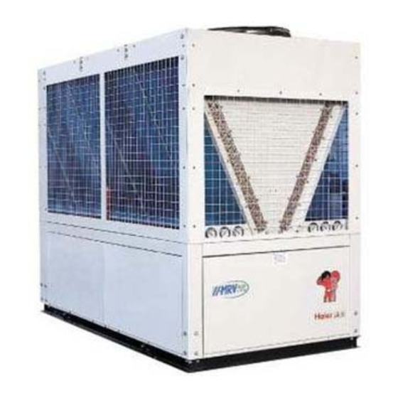
- Page 1 Air Cooled Module Water Chiller Installation, operation and technical manual Heat pump / Cooling only R22 refrigerant 100KW 3PH, 380V, 50Hz Haier Commercial Air Conditioning MANUAL CODE: SYJS-035-06REV.2 2008-04-30...
-
Page 2: Table Of Contents
HAIER CHILLER TABLE OF CONTENTS 1. Nomenclature……………………………………………………………………………………………………..3 2. Product character…………………………………………………………………………………………………3 3. Specifications……………………………………………………………………………………………………..5 4. Dimension data…………………………………………………………………………………………………...7 5. Installation and debugging………………………………………………………………………………………8 6. Refrigerant circuit……………………………………………………………………………………………….10 Water system installation diagram…………………………………………………………………………….11 8. Wiring diagrams………………………………………………………………………………………………..13 Auxiliary electric heating function control. ……………………………………………………………………14 10. Water pump operation control(valid when water pump and the unit controlled simultaneously)……….14 11. -
Page 3: Nomenclature
HAIER CHILLER 1. Nomenclature Code Explanation for chiller capacity (for chiller compressor type Centrifugal chiller: product type unit character suitable voltage design number system Rt; other: KW) A 100-115V, 60Hz 1 fixed frequency A-G Centrifugal chiller A air cooled R407C B water cooled W 220-240V, 50Hz... - Page 4 HAIER CHILLER system will start up automatically. When all indoors arrive the set temperature, the master unit will stop. Energy saving. Auto check technology: The system can check the operation status automatically; all kinds of sensors will transmit the operation parameters to the chip. By pressing the buttons, all the parameters can display on the liquid crystal screen.
-
Page 5: Specifications
HAIER CHILLER 3. Specifications Model CA0100MANB CA0100AANB Nominal cooling capacity Nominal heating capacity Total power input 32.25 32.25 Start current Running current Max. running current (in the electric control box) 67.5 67.5 Recommended circuit GV2-M22C(23A)/GV2- GV2-M22C(23A)/GV2- breaker M16C(10) M16C(10) 3PH, 380V, 50Hz... - Page 6 Running weight 1150 1150 polyester painted galvanized steel plate, Haier gray Casing Nominal working condition (cooling ):water inlet temp. 12 ℃ , water outlet temp. 7℃, ambient temp. 35℃。 Nominal working condition (heating ):water inlet temp. 40℃, water outlet temp. 45 ℃, ambient temp. (DB)7℃, (WB)6℃...
-
Page 7: Dimension Data
HAIER CHILLER 4. Dimension data 4.1 Installation dimension 2520 1350 ACOEM @POIEO ACOEM HJIEO =KPJDCOHKJ 2491+>KHNOHJF >KIE, ?JNOCIIHJF >KIE 2711 +?JNOCIIHJF >KIE, 1290 4.2 Foundation dimension 4.2.1 The bearing capacity of the foundation shall be designed according to the unit's operation weight. -
Page 8: Installation And Debugging
HAIER CHILLER 5. Installation and debugging 5.1 Freight Check All the units are tightly fastened on the wooden pallet by the bolts. Before leaving factory, the units are all checked and pre-filled with refrigerant and refrigerant oil, both of which are the precise amount the unit operation needs. - Page 9 HAIER CHILLER 5.4.8 The installation and thermal insulation of the water pipes of the air conditioning system shall be designed and instructed by the professionals and shall implement the relevant regulations of the Installation Standard for HV & AC. 5.4.9 The external water pipe system must be equipped with anti-vibration hose, water filter, electronic water cleaner, check valve, drain valve, discharging valve, stop valve and expansion tank, etc.
-
Page 10: Refrigerant Circuit
HAIER CHILLER 6. Refrigerant circuit CA0100AANB four-way valve water inlet water hole side gas-liquid heat segregater water exchanger outlet compressor one way hole valve accumulator filter drier air side heat liquid side exchanger glass Cooling Heating thermostatic expansion valve CA0100MANB... -
Page 11: Water System Installation Diagram
HAIER CHILLER 7. Water system installation diagram 35G9E 0LFG9A ~BFG5@@5G=CB {=5;E5A {=5;E5A C: J5G9E D=D9 7CBB97G=CB 69GJ99B G<E99 HB=GF CI9E:@CJ <C@9 J5G9E FHDD@L <C@9 J5G9E CHG@9G 8E5=B5;9 J5G9E =B@9G <C@9 19EA=B5@ ,CG9v mj }@9K=6@9 <CF9 >C=BG nj .E9FFHE9 ;5H;9 oj 1CG5@ J5G9E E9GHEB F9BFCE =BFG5@@ D@579 pj 1<9EACA9G9E... - Page 12 HAIER CHILLER 1LD=75@ 3=E=B; 5B8 .=D9 zCBB97G=CB +5FG9E +C8H@9 0@5I9jAC8H@9 0@5I9jAC8H@9 35G9E ~B@9G 35G9E -HG@9G .CJ9E {=FGE=6HG=CB 3=E98 zCBGEC@@9E ,CG9v mk 2B=G .CJ9E 0HDD@L zCE8 pk 35G9E .HAD .CJ9E zCE8 nk +C8H@9j65F98 2B=G zCAAHB=75G=CB 3=E9 qk z56@9 GC 2B=G .CJ9E {=FGE=6HG=CB yCK ok 2B=G -D9E5G=CB zCBGEC@@9E 3=E=B;...
-
Page 13: Wiring Diagrams
HAIER CHILLER 8. Wiring diagrams a. The unit wiring diagram... - Page 14 HAIER CHILLER 0010452203 for CA0100AANB...
-
Page 15: Auxiliary Electric Heating Function Control
HAIER CHILLER b. The driving wiring diagram circuit circuit circuit breaker breaker breaker slave slave master unit 15 unit 1 c. The communication wiring diagram M C U G N D G N D G N D A G N D... -
Page 16: The Terminal Simultaneous Control
HAIER CHILLER 11. The terminal simultaneous control Connect the passive port of the terminal controller to the simultaneous control port in the controller of the master module unit. When the unit is running and the controller is in simultaneous control state, when one of terminal unit starts up, the chiller system will start up automatically. -
Page 17: Wired Controller Functions
HAIER CHILLER 12. Wired controller functions ?Yb_[Qg bSaUU]; JQ]U[ TYb_[Qg G^TU TYb_[Qg >^TU TYb_[Qg JQaQ\UcUa.bUccY]W Y]TYSQcY^] S^^[Y]W XUQcY]W AQd[c S^TU Y]TYSQcY^] >[^SZ TYb_[Qg JQaQ\UcUa 0 VQd[c S^TU X^da \Y]dcU KUbc^aQR[U VQd[c S^TU Y]TYSQcY^] MY\Ua bUccY]W TYb_[Qg LUaY^db VQd[c Y]TYSQcY^] Idc_dc U`dY_\U]c TYb_[Qg... - Page 18 HAIER CHILLER Controller system is constituted by 1 to 16 HAC-F3S-H PCB and one or many MCU. parallel connect each MCU when use many MCU. Module PCB Module PCB Module PCB (1#) r(2#) r(3#) RS485 Module PCB Module PCB (4#) (16#) There should be at least one main module PCB in the system, the address of which is 0000 and the No.
-
Page 19: Control Functions
HAIER CHILLER temperature setting, clock setting, timer setting, reset/dark. General layout of all touch buttons is illustrated in the above diagram. Press valid button once or receive signal by remote control, LCD will display the corresponding mode, backlight lightens, the buzzer gives a beep, and backlight is off 10 seconds later automatically. - Page 20 HAIER CHILLER 12.3.4 Mode setting. Press [MODE] to enter the mode setting. Controller recognizes controller mode automatically. Mode setting cycles between cooling and heating. 12.3.5 Temperature-setting When the unit is on, you can adjust controller to set temperature. Press the [▲] and [▼] keys, the temperature will increase and decrease accordingly.
- Page 21 HAIER CHILLER the number of system modules used. There is a dip switch which includes 4-digit set on the controlling panel, according to which we can set the module number of unit. After the communication between a module and the wired controller is established, there is one lighting dot representing it on the wired controller.
- Page 22 HAIER CHILLER b. Timer On/Off Timer on, timer off, cycling timer setting and combination timer setting can be chosen through wired controller. Each combination timer setting is valid for within 24 hours and cycling timer setting is valid all the time.
- Page 23 HAIER CHILLER When the there is no or litter water flow in the pipe, the switch will cuts off control circuit to close the unit, protect the unit and compressor. e. Overload protection of compressor There is a crankcase-heater and a thermal overload relay equipped on the compressor.
- Page 24 HAIER CHILLER Parameter name Unit number Original setup cancellation General return water temperature PC01 0 ℃ -9 ℃ 9 ℃ 0 ℃ --9 ℃ 9 ℃ 1# liquid pipe temperature PC02 2# liquid pipe temperature PC03 0 ℃ --9 ℃...
- Page 25 HAIER CHILLER 12.5.8 Protection temperature parameter Name Unit Original Cancellation number setup Cooling and frost-proof protection EP01 4°C 10°C -5°C Heating and over-temperature EP04 60°C 80°C 55°C protection Winter frost-proof protection EP07 3°C 8°C -2°C 12.5.9 Protection time parameter Name...
- Page 26 HAIER CHILLER 3#compressor overload protection Er: 03 3#compressor stops Serious fault 1#system high pressure protection Er: 04 System 1 stops Serious fault 2#system high pressure protection Er: 05 System 2 stops Serious fault 3#system high pressure protection Er: 06 System 3 stops...
- Page 27 HAIER CHILLER 12.7.2 Operation condition Operation ambient temp.: -10℃—+60℃ Preserved ambient temp.: -20℃—+70℃ Relative humidity: 40%—98% 12.7.3 Temp. sensor System total return water temp. sensor: 3470-502±1% System total outlet water temp. sensor: 3470-502±1% Module outlet water temp. sensor: 3470-502±1% Outdoor ambient temp. sensor: 3470-502±1%...
- Page 28 HAIER CHILLER that there is no leakage and air bubbles. 12.9 Inspection of operation status Please inspect the items as follows: 1. Temperature of water entering into the heat exchanger 2. Temperature of water returning from the heat exchanger 3. Flow rate at the exit of the heat exchanger 4.
- Page 29 HAIER CHILLER 13. Control functions 13.1 Cooling mode 13.1.1 Enter cooling mode Control the system total return water temp.: the setted temp. of cooling mode is 12℃; Control the system total outlet water temp.: the setted temp. of cooling mode is 12℃;...
- Page 30 HAIER CHILLER Download Standby Upload Emergency Compressor area area area stop area state -[SP01] +[SP01] tr/o Fig. 14-1 Compreesor running diagram in cooling mode 13.1.5 Cooling (heating) water pump running regulation Cooling (heating) water pump will startup when PCB working or protection in winter, the working of pump is concerned with the state of water flow switch.
- Page 31 HAIER CHILLER display [Er:08] code, the corresponding module will stop for protection; ④ When the outdoor ambient temp. sensor damage, the system [UNIT] will flash and display [Po:01] code; ⑤ When the condenser coil temp. sensor of No.1 module damage, the corresponding module No. will flash and display [Pr:01] code;...
- Page 32 HAIER CHILLER startup protect time ≥ [EC02]; When T - [SP01] <T ≤T , the compressor will keep its original state, there is tr/o a setted difference temp. [SP01] to prevent compressor from conversing ON/OFF frequently; When >T +[SP02], PCB entering Emergency stop area.
- Page 33 HAIER CHILLER code, system will stop for protection; ② When the system total outlet temp. sensor damage, the system [UNIT] will flash and display [Eo:02] code, module will stop for protection; ③ When the module total outlet temp. sensor damage, the corresponding module No. will flash and display [Er:08] code, the corresponding module will stop for protection;...
- Page 34 HAIER CHILLER If the compressor accumulative running time over the setted value [HF05], one of the enter conditions is meeted. b. Temp. difference condition between outdoor coil and outdoor ambient temp. Outdoor coil temp. T will be lower than outdoor ambient temp. T...
-
Page 35: Maintenance
HAIER CHILLER 14 Maintenance Note: Before performing any maintenance and repair to the unit, please cut off power supply. Electricity leakage will cause body injury. In order to exert the unit's performance fully, must pay attention to the following items: a. - Page 36 HAIER CHILLER MAINTENANCE a. Before replacing any component of the refrigeration circulation, make sure the refrigerant has been evacuated from both the high side and the low side of the unit. The control elements of refrigeration system are highly sensitive and they must be handled very carefully if a replacement is required. Make sure they are not overheated during the welding process by protecting them with wet cloth.
- Page 37 HAIER CHILLER Sincere Forever Haier Group Haier Industrial Park, No.1, Haier Road 266101, Qingdao, China http://www.haier.com...
Need help?
Do you have a question about the CA0100MANB and is the answer not in the manual?
Questions and answers