
Related Manuals for ZALMAN CNPS10X Optima (2011)


Summary of Contents for ZALMAN CNPS10X Optima (2011)
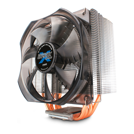
- Page 1 User's Manual CNPS10X Optima (2011) Intel Socket LGA 2011 V3/2011/1366/1156/1155/1151/1150/775 CPUs AMD Socket FM2/FM1/AM3+/AM3/AM2+/AM2 CPU & APUs To ensure safe and easy installation, Please read the following precautions. www.ZALMAN.com Ver. 150806...
-
Page 2: Specifications
Check the components list and condition of the product before installation. If any problem is found, contact the retailer to obtain a replacement. During transportation of the system, the cooler must be removed. Zalman is not responsible for any damages that occur during the transport of a system. -
Page 3: Common Components
English 3. Components 1) Common Components User's Manual Cooler Backplate Fan Fixing Clips Side Caps Bolts Nuts Loaging Block Thermal Grease Double-sided Tape [ZM-STG2M] 2) Intel Components 3) AMD Components Socket FM2/FM1/AM3+/AM3/AM2+/AM2 - Socket LGA 2011 V3/2011/1366/1156 /1155/1151/1150/775 - Stand off Intel Clip Stand-off AMD Clip... -
Page 4: Installation Requirements
English 4. Installation Requirements 1) Space Requirements The cooler’s installation requires an unobstructed space of 85mm(width), 132mm(length), and 152mm(height), with the CPU as a central reference point. Please check if components such as ODDs and PSU protrude into the required space. -
Page 5: Installation
English 5. Installation A. LGA Intel Socket Installation Lastly, fasten the four screws to secure the clips (Please go to Page 8 for further instructions) Intel Socket 2011 V3 / 2011 User ① - ⓐ Partially unscrew the four bolts located on the base of the CPU cooler. Then, insert the Intel Clips between the base and the heatpipe cover, with the clips bent away from the heatsink. - Page 6 English ② Install the Bolts to the Backplate according to the socket type and secure them with Side Caps. ※ Backplate is not needed for LGA 2011 V3 / 2011 sockets. Socket 775 Socket 1156/1155/1151/1150 Socket 1366 Caution Take note of the orientation of the Nuts and the Side Caps. ③...
- Page 7 English ③ - ⓑ Socket 775 Installation Peel off the Loading Block cover and attach it to the Backplate with the sticky side facing the center of the Backplate. Loading Block Peel off one side of the Double-sided Tape and attach it with the sticky side facing the Loading block.
- Page 8 English ④ - ⓐ ④ - ⓑ Socket 1366 / 1156 / 1155 / 1151 / 1150 / 775 Use r Socket 2011 V3 / 2011 Use r Stand-off Attach the Backplate assembly to the back side of the Fasten the four Stand-offs to the motherboard by aligning the Nuts to the motherboard motherboard.
- Page 9 English ⑦ Position the fan as low as possible. Lowering the fan helps to cool the components on the motherboard. ⑧ Connect the cooler’s 4-pin connector to the motherboard’s CPU Fan header. Caution Please make sure that PWM Control Mode is activated in the motherboard’s BIOS settings.
- Page 10 English B . AMD Socket Installation ① Partially unscrew the four bolts located on the base of the CPU cooler. Then, insert the AMD Clips between the base and the heatpipe cover, with the clips bent away from the heatsink. AMD Clip Caution The holes in the Clip (as shown...
- Page 11 English ③ Peel off the Loading Block cover and attach it to the Backplate with the sticky side facing the center of the Backplate. Loading Block Peel off one side of the Double-sided Tape and attach it with the sticky side facing the Loading block.
- Page 12 English ⑤ Attach the Backplate assembly to the back side of the motherboard by aligning the Nuts to the motherboard mounting holes. If you were unsuccessful at first attempt, you may continue with the installation without the Double-sided Tape as it is not a necessary component.
- Page 13 English ⑧ Position the fan as low as possible. Lowering the fan helps to cool the components on the motherboard. ⑨ Connect the cooler’s 4-pin connector to the motherboard’s CPU Fan header. Caution Please make sure that PWM Control Mode is activated in the motherboard’s BIOS settings.
Need help?
Do you have a question about the CNPS10X Optima (2011) and is the answer not in the manual?
Questions and answers