Table of Contents
Advertisement
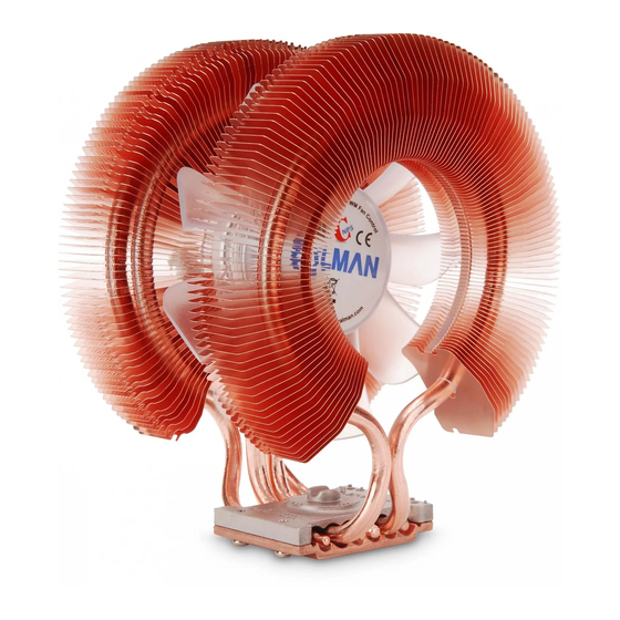
User's Manual
Intel Socket 2011/1366/1156/1155/775 CPU
Core i7 Extreme, Core i7, Core i5, Core i3, Core 2 Extreme, Core
2 Quad, Core 2 Duo, Pentium Dual-Core, Pentium D, Pentium 4,
Celeron D
AMD Socket FM1/AM3+/AM3/AM2+/AM2 CPU
Zambezi, Llano, Phenom II, Phenom, Athlon II, Athlon X2, Athlon
FX, Athlon, Opteron Dual-Core, Opteron, Sempron
Intel Socket 1366/1156/1155/775 CPU
Core i7 Extreme, Core i7, Core i5, Core i3, Core 2 Extreme, Core
2 Quad, Core 2 Duo, Pentium Dual-Core, Pentium D, Pentium 4,
Celeron D
AMD Socket FM1/AM3+/AM3/AM2+/AM2 CPU
Zambezi, Llano, Phenom II, Phenom, Athlon II, Athlon X2, Athlon
FX, Athlon, Opteron Dual-Core, Opteron, Sempron
CNPS9900 Max
CNPS9900A LED / NT
To ensure safe and easy installation, please read
the following precautions
www.ZALMAN.com
Ver. 3.0
Advertisement
Table of Contents

Related Manuals for ZALMAN CNPS9900 Max


Summary of Contents for ZALMAN CNPS9900 Max
- Page 1 User’s Manual CNPS9900 Max Intel Socket 2011/1366/1156/1155/775 CPU Core i7 Extreme, Core i7, Core i5, Core i3, Core 2 Extreme, Core 2 Quad, Core 2 Duo, Pentium Dual-Core, Pentium D, Pentium 4, Celeron D AMD Socket FM1/AM3+/AM3/AM2+/AM2 CPU Zambezi, Llano, Phenom II, Phenom, Athlon II, Athlon X2, Athlon...
- Page 2 Check the components list and condition of the product before installation. If any problem is found, contact the retailer to obtain a replacement. Zalman Tech Co., Ltd. is not responsible for any damages due to overclocking. Before transportation of the system, the cooler must be removed.
- Page 3 Silver Bolts B (3mm) (Socket 1366 ) (Socket 2011, (Socket 1156/1155/775/AMD) CNPS9900MAX Only) Nuts Double-sided Tape Loading Block 2) Intel Components 3) AMD Components CNPS9900 MAX : Socket 2011/1366/1156/1155/775 Socket FM1/AM3+/AM3/AM2+/AM2 CNPS9900A LED/NT : Socket 1366/1156/1155/775 AMD Clip Intel Clip .COM...
- Page 4 1) Space Requirements The cooler’s installation requires unobstructed space with dimensions of 133mm(width), 96mm(length), 154mm(height), and the CPU as a central reference point. Please check if components such as ODDs and PSU protrude into the required space. 2) Air Guide Removal Air guides on enclosures must be removed, before the cooler’s installation, for they protrude into the cooler’s required space.
- Page 5 Base Cover. Align 1) Intel Socket 2011 Installation (CNPS9900 MAX Series Only) - Apply a suitable amount of the included Thermal Grease on the CPU’s surface and then fasten the Bolts to install the cooler. Wrench...
- Page 6 2) Intel Socket 1366/1156/1155/775 Installation Install Bolts to the Backplate according to the Socket Type and secure with Side Caps. Socket 775 Socket 1156/1155 Socket 1366 Caution Take note of the orientation of the Nuts and the Side Caps. Socket 1366/1156/1155 Installation Attach Double-sided Tape to the center of the Backplate and remove the Double-sided Tape’s Cover.
- Page 7 Socket 775 Installation Remove the Sticker Cover from the Lower Tier of the Loading Block and attach to the Backplate. Loading Block Attach Double-sided Tape to the Loading Block and remove the Double-sided Tape Cover. Double-sided Tape Caution Please make note of the orientation of the Loading Block’s Installation. .COM...
- Page 8 Align the Backplate’s Nuts with the motherboard’s Clip Support installation holes and then fasten to the motherboard. Apply a suitable amount of the included Thermal Grease on the CPU’s surface and then fasten the Bolts to install the cooler. Gold Bolt (Socket 1366) Sliver Bolt B (3mm) (Socket 1156/1155/775)
- Page 9 B. AMD Socket Installation 1) AMD Socket FM1/AM3+/AM3/AM2+/AM2 Installation Unfasten the Bolts on the Cooler’s Base one thread, insert the AMD Clip between the Cover and the Base, and then refasten the Bolts. Caution Make sure the AMD Clip’s ingresses the Base Cover.
- Page 10 Remove the Sticker Cover from the Lower Tier of the Loading Block and attach to the Backplate. Loading Block Attach Double-sided Tape to the Loading Block and remove the Double-sided Tape Cover. Double-sided Tape Caution Please make note of the orientation of the Loading Block’s Installation. Disassemble the motherboard’s Clip Support.
- Page 11 Align the Backplate’s Nuts with the motherboard’s Clip Support’s installation holes and fasten to the motherboard. Apply a suitable amount of the included Thermal Grease on the CPU’s surface and then fasten the Silver Bolts to install the cooler. (Please use the designated Bolts in accordance with Socket Types.) Wrench Caution Check the size of the silver-...
Need help?
Do you have a question about the CNPS9900 Max and is the answer not in the manual?
Questions and answers