Table of Contents
Advertisement
Advertisement
Table of Contents
Troubleshooting

Related Manuals for Furuno PG-700


Summary of Contents for Furuno PG-700
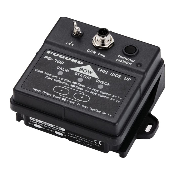
- Page 1 OPERATOR'S MANUAL INTEGRATED HEADING SENSOR PG-700 MODEL www.furuno.co.jp...
- Page 3 How to discard a used battery Some FURUNO products have a battery(ies). To see if your product has a battery(ies), see the chapter on Maintenance. Follow the instructions below if a battery(ies) is used. In the European union The crossed-out trash can symbol indicates that all types of batteries must not be discarded in standard trash, or at a trash site.
-
Page 4: Safety Instructions
SAFETY INSTRUCTIONS Read these safety instructions before you operate the equipment. Indicates a condition that can cause death or serious injury if WARNING not avoided. Indicates a condition that can cause minor or moderate injury if CAUTION not avoided. Warning, Caution Mandatory Action Prohibitive Action Instructions for the installer... -
Page 5: Table Of Contents
1.4 Heading Adjustment ....10 1.5 Input/Output Data List....12 OPERATION ....... 13 2.1 Key and Lamp Explanation..13 2.2 How to Turn on the PG-700 ..14 MAINTENANCE AND TROUBLESHOOTING ....15 3.1 General Maintenance ....15 3.2 Lamp status display ....16 3.3 Troubleshooting ....... -
Page 6: Foreword
FOREWORD Congratulations on your choice of the PG-700 Integrated Heading Sensor. We are confident you will see why the FURUNO name has become synonymous with quality and reliability. For over 60 years FURUNO Electric Company has enjoyed an enviable reputation for innovative and dependable marine electronics equipment. -
Page 7: System Configuration
SYSTEM CONFIGURATION The solid line below shows the basic system configuration. SENSOR PG-700 FURUNO CAN bus Device* JUNCTION BOX FI-5002 12 VDC** *: NavNet 3D, FI series instrument, etc. **: Not necessary if FURUNO CAN bus network supplies power. -
Page 8: Equipment List
EQUIPMENT LIST Standard Equipment Code Name Model Quantity Remark number Sensor PG-700 Installation CP64-02800 1 set • Cable set materials Type: M12-05BM+05BF-060 Code number: 000-167-964-11 Quantity: 1 • Self-tapping screws Type: 4x16 SUS304 Code number: 000-162-605-10 Quantity: 3 Optional Equipment... -
Page 9: How To Install The Equipment
HOW TO INSTALL THE EQUIPMENT Installation Considerations Mount the unit with the lamps and keys face up on a horizontal surface. The unit can be mounted on a desktop or bulkhead. Overhead mounting is not allowed. When selecting a mounting location, observe the following to ensure optimal performance: •... - Page 10 Battery 12 VDC If you connect PG-700 directly to the instrument, or to a network, each device must be tem- porarily connected to each other, and a power supply 12 VDC (see page 6). 2. Place the unit at the intended mounting position and supply power. Verify that the STATUS lamp is not lit red.
- Page 11 1. HOW TO INSTALL THE EQUIPMENT 4. Slowly turn the unit (one turn per minute) at the mounting position (turn one - two times to achieve the results as shown in the left figure below). If successful, the STATUS and CHECK lamps light green. If fails, the STATUS lamp lights red. CALIB STATUS CHECK...
- Page 12 1. HOW TO INSTALL THE EQUIPMENT Bulkhead mounting The unit can be mounted to the bulkhead either parallel or vertical to the bow. 1. Remove two screws at the bottom to detach the mounting base. 2. Remount the base upside down using the two screws which were unscrewed in the above step.
-
Page 13: Wiring
1. HOW TO INSTALL THE EQUIPMENT Wiring Connect a termination resistor at both ends of the backbone of CAN bus devices. PG-700 incor- porates a termination resistor. Turn the switch on/off as applicable. If using the optional Junction Box FI-5002 Connect the unit and the FI-5002 using cable M12-05BM+05BF-060 (supplied as installation ma- terials). - Page 14 1. HOW TO INSTALL THE EQUIPMENT If connecting directly to the instrument When connecting FI-502/FI-504/FI505 instruments, use supplied cable M12-05BM+05BF-060. Do not cut the cable. Turn on the PG-700 termination switch. M12-05BM+05BF-060 (Connector at both ends, 6 m cable) FI-50-DROP...
- Page 15 1. HOW TO INSTALL THE EQUIPMENT • If connecting M12-05BM+05BF-060 cable to a T-type connector as a backbone, as shown be- low, turn the termination switch on. Termination switch ON Lamp ON Ground GO TO LIST POINTS ROUTE wire FI-50 DIGITAL DATA CANCEL...
-
Page 16: Compensation Of Deviation
After finishing the installation completely, do the compensation of deviation in calm sea conditions as follows: 1. Turn the PG-700 on and verify that the STATUS lamp is not lit red. 2. Press and hold the [+] and [-] key together for 3 seconds, and release both keys. - Page 17 1. HOW TO INSTALL THE EQUIPMENT Note: When doing deviation correction, the surrounding environment and ship position will have an effect on the time it takes to succeed in the correction. CALIB STATUS CHECK : ON (green) : OFF After five sec. : Flashing (green) CALIB STATUS...
-
Page 18: Heading Adjustment
1. HOW TO INSTALL THE EQUIPMENT Heading Adjustment The amount of adjustment required for the heading depends on the outcome of the previous sec- tion [1.3 Compensation of Deviation]. Do the following to correct the discrepancy. CAUTION Before doing the heading adjust- ment, turn off the autopilot. - Page 19 1. HOW TO INSTALL THE EQUIPMENT Set interval Lamp Status Short press [+] key +0.1° Each time you press the [+] key, the STATUS lamp within 5 seconds (increases 0.1° will light on and off. with every press) CALIB STATUS CHECK 1st time CALIB...
-
Page 20: Input/Output Data List
GMM Message (PGN: 126720, #4=4)*2 PGN: Parameter Group Number. Equivalent to NMEA0183 sentence. *1: Data can be output at an interval of 25ms and over (5ms steps) according to the request from another device. *2: PGN registered to Furuno Electric Co. Ltd. -
Page 21: Operation
Before operating: • This unit contains magnetic components. Keep away from metals (when the ship inclines, be sure no metal objects roll towards the PG-700). • When navigating in the vicinity of large structures (bridges, etc.), an bearing error may occur. -
Page 22: How To Turn On The Pg-700
The unit has no power switch. Supply the +12 VDC power via the optional junction box FI-5002 or FURUNO CAN bus device. When power is received by the sensor, the unit will automatically check ROM and RAM status. After this, the lamps light as shown below:... -
Page 23: Maintenance And Troubleshooting
MAINTENANCE AND TROUBLE- SHOOTING This chapter discusses maintenance and troubleshooting procedures to ensure optimal perfor- mance of the equipment. NOTICE o not apply paint, anti-corrosive sealant or contact spray to plastic parts or equipment coating. Those items contain products that can damage plastic parts and equipment coating. -
Page 24: Lamp Status Display
3. MAINTENANCE AND TROUBLESHOOTING Lamp status display Lamp Status Unit operating condition Normal state • Deviation correction: success CALIB STATUS CHECK • Angular velocity sensor: initialization complete • Deviation correction: success • Angular velocity sensor: initializing CALIB STATUS CHECK • Deviation correction: not implemented (or failed) CALIB STATUS CHECK... -
Page 25: Troubleshooting
3. MAINTENANCE AND TROUBLESHOOTING Troubleshooting If a problem occurs, first do the following inspections. If the problem persists, contact the dealer or a qualified service technician. Problem Action Lamps do not light. • Check to ensure the connector is tightened. •... -
Page 26: Specifications
FURUNO PG-700 SPECIFICATIONS OF INTEGRATED HEADING SENSOR PG-700 GENERAL 1.1 Heading Accuracy ±1.0° (horizontal) ±10.0° (within 30°), ±20.0° (within 45°) 1.2 Display resolution 0.1° 1.3 Follow-up 100°/s rate-of turn 1.4 Interface CAN bus: 1 channel Output PGN 126720 Input settings Output interval, Bearing offset 1.5 Data Update... - Page 27 4/Sep/09 R.Esumi...
- Page 28 4/Sep/09 R.Esumi...
- Page 32 : +81-(0)798-65-4200 A : SEP 2009 All rights reserved. Printed in Japan A1 : OCT . 30, 2009 Pub. No. OME-72760-A1 *00017182710* *00017182710* (TOMA ) PG-700 *00017182710* *00017182710* * 0 0 0 1 7 1 8 2 7 1 0 *...
Need help?
Do you have a question about the PG-700 and is the answer not in the manual?
Questions and answers