Table of Contents
Advertisement
Quick Links
Download this manual
See also:
Operating Manual
Advertisement
Table of Contents

Related Manuals for Meyra 1.595-603


Summary of Contents for Meyra 1.595-603
- Page 1 Electric wheelchair Model 1.595 – 603 Vertical Junior Model 1.595 – 604 Vertical Senior Operating manual W e m o v e p e o p l e .
-
Page 2: Table Of Contents
Contents Introduction Indications Specifications Acceptance Adjustment Life span Overview Model: 1.595 – 603 / 1.595 – 604 Quick guide Handling the electric wheelchair Securing the electric wheelchair Functional checks Driving Speed limitation Brakes Service brake Braking the wheelchair Parking brake Locking the brakes Releasing the brakes Drive-/push mode... - Page 3 Arm supports Angle of the arm supports Swivelling up the arm supports Swivelling down the arm supports Back support Head support Adjustment of the head support Removing and height adjusting the head support Adjusting the head support during handicapped transport inside a motor vehicle Holder for chin operation Leg support Folding up the leg support...
- Page 4 Shoulder strap Fastening the shoulder strap Adjustment of belt length Emergency switch Raising the seat Lowering the seat Loading and transportation Loading Transport of people inside a motor vehicle Transport security Maintenance Maintenance Maintenance schedule Fuses Replacing the fuses Tyre damage on pneumatic tyres Lighting Adjusting the headlights Fault correction...
-
Page 5: Introduction
Like any other vehicle, an electric wheel- < www.meyra.com >. chair is a technical aid. It is subject to ex- planations, requires regular care and can ☞ Contact your specialist dealer when re- cause danger when used improperly. -
Page 6: Indications
INDICATIONS If the following indications occur we rec- The electric wheelchair, with attached leg ommend the application of this mobility supports and arm supports, serves exclu- product: sively for the conveyance of one sitting per- son. Other pulling or transporting uses do ☞... -
Page 7: Adjustment
ADJUSTMENT LIFE SPAN The specialist workshop will hand out the We expect an average life span of about electric wheelchair to you under considera- 5 years for this product, as far as the product tion of all relevant safety instructions, ready is applied for its designated purpose and all for operation and adjusted to your needs. -
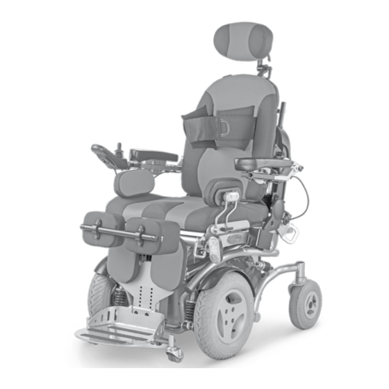
Page 8: Overview
OVERVIEW Model: 1.595 – 603 / 1.595 – 604 The overview shows the most important components and operating equipment. Pos. Description (10) Selection lever drive-/push mode (1) Chest strap (11) Seat unit (2) Back support upholstery (12) Head support (3) Arm support (13) Operating module (4) Side cushion (14) Driving wheel... -
Page 9: Quick Guide
QUICK GUIDE ☞ Note: The following quick guide does not re- place the reading and observing of the documentation belonging to the elec- tric wheelchair. Operation adjustments through the operating module With the mode – key, depending on the equipment, the adjustment menus can be selected. -
Page 10: Handling The Electric Wheelchair
HANDLING THE ELECTRIC Speed limitation WHEELCHAIR The speed limitation to 3 km/h serves the safety and is activated in the following set- tings: Securing the electric wheelchair – Seat height lower than 10 mm The electric wheelchair is to be secured as follows to prevent it from rolling off unin- –... -
Page 11: Locking The Brakes
Locking the brakes To engage the brakes swivel the selection lever drive-/push mode on both sides down as far as possible into drive mode [1]. ☞ Activation of the selection lever is in- tended for an accompanying person. Attention: It should not be possible to push the electric wheelchair forward when the brakes are engaged. -
Page 12: Drive-/Push Mode
Drive-/push mode Attention: Only switch the electric wheelchair to push mode when it is standing still for positioning or in case of emergencies, but not on slopes/hills. ☞ The electric magnetic brakes are switched off in the push mode. – A braking of the electric wheelchair is then only possible by switching to the drive mode. -
Page 13: Selecting The Operation
SELECTING THE OPERATION In order to obtain operational readiness of the electric wheelchair the following direc- tions are to be carried out in the indicated order. ☞ Note: Charge the drive batteries via the oper- ating module before the first journey. Selecting the motor mode Switch the drive motors to the drive mode [1]. - Page 14 Position of the operating module ☞ The operating module should be positioned in such a way that you can comfortably and safely steer the electric wheelchair. ☞ The distance of the operating mod- ule to the padded arm supports can be adjusted after loosening the clamping screw (3).
-
Page 15: Pre-Operation Checks
Pre-operation checks Before starting to drive, the following should be checked: ☞ the battery charging condition, ☞ the setting of the preselected final speed. – For this observe the operating manual < Operating module >. Battery charging procedure ☞ For the battery charging procedure also observe the operating manual of the battery charger. -
Page 16: Positioning The Operating Module
Positioning the operating module Function description You will find a detailed description of the keys and symbols in the operating manual for < Operating module >. The position of the operating module can be adjusted to suit the individual size of the user. -
Page 17: Swivelling The Operating Module
Swivelling the operating module With the swivel away operating module adapter the operating module can be swiv- elled back to the side [1] so that it is located parallel to the arm support. This makes it possible, for example: – to drive closer to a table, –... -
Page 18: Arm Supports
ARM SUPPORTS The arm supports can be adjusted in height by a specialist dealer to suit the needs of the user. Attention: Do not use the arm supports to lift or carry the wheelchair. Angle of the arm supports The angle of the arm supports can be ad- justed to the desires of the user. -
Page 19: Swivelling Up The Arm Supports
Swivelling up the arm supports The arm supports can be swivelled upward when necessary [1]. Pull out the button (2) that locks down the arm support and swivel the arm support up as far as possible. ☞ Note: Support the arm support slightly with one hand. -
Page 20: Back Support
BACK SUPPORT The angle of the back support (1) can be ad- justed through the operating module. ☞ Note: For adjustment view chapter < Mode- menu > in the operating manual < Op- erating module > resp. chapter Quick guide on page 9 within this docu- ment. -
Page 21: Leg Support
LEG SUPPORT The angle of the leg support (1) can be ad- justed through the operating module. ☞ Note: For adjustment view chapter < Mode- menu > in the operating manual < Op- erating module > resp. chapter Quick guide on page 9 within this docu- ment. -
Page 22: Knee Cushions
Knee cushions The knee cushions (1) are removable and can be adjusted in height and depth by your specialist dealer. Removing/attaching the knee cushions In order to remove/attach the knee cush- ions, pull up the locking lever (2) first. Af- terwards remove (3) or attach (4) the knee cushions. -
Page 23: Side Cushions
SIDE CUSHIONS The side cushions (1) are height, seat width and depth adjustable as well as removable. Adjusting the side cushions After loosening the clamping lever (2) the respective side cushion can be adjusted to the desired height and position. Afterwards retighten the clamping lever (2). -
Page 24: Torso Supports
TORSO SUPPORTS The torso supports (1) are continuously height, width and depth adjustable as well as removable by your specialist dealer. SPLAY WEDGE The splay wedge (2) can also be mounted retrospectively in a specialist workshop. Removing/attaching the splay wedge Loosen the clamping screw (4) for removal (3) and attachment (5). -
Page 25: Seat
SEAT ☞ Note: For adjustment view chapter < Mode- menu > in the operating manual < Op- erating module > resp. chapter Quick guide on page 9 within this docu- ment. ☞ Observe chapter Technical data on page 39. Seat inclination (camber) The seat inclination (1) can be adjusted through the operating module. -
Page 26: Seat Height Adjustment
Seat height adjustment The seat height [1] can be adjusted through the operating module. ☞ Note: This continuously increases the seat height by up to 300 mm. ☞ In combination with the additional seat raiser of 150 mm the seat height can now be increased up to 450 mm. -
Page 27: Standing Function
Standing function The standing position [1] can be adjusted through the operating module. ☞ Note: Rising may only be carried out with the chest strap (2) applied and with correct- ly adjusted knee cushions (3). ☞ Therefore observe the chapters Knee cushions on page 22 and Chest strap on page 29. -
Page 28: Lying Function
Lying function The lying position [1] can be adjusted through the operating module. ☞ Note: The lying position [1] may only be set with correctly adjusted knee cushions (2) and the chest strap applied (3). ☞ Therefore observe the chapters Knee cushions on page 22 and Chest strap on page 29. -
Page 29: Adjusting The Seat Depth
Adjusting the seat depth The seat depth can be adjusted by reposi- tioning the back support [1]. Attention: A retrospective repositioning of the back support is only to be carried out in a specialist workshop! CHEST STRAP The chest strap (2) prevents falling forward. Fastening the chest strap Pull both straps forward and place close to the body. -
Page 30: Shoulder Strap
SHOULDER STRAP The shoulder strap (1) serves for additional fixation of a person sitting the wheelchair. – Additional stabilisation of the sitting position. – Prevents falling forward. – Continuous adjustment to suit the us- er’s needs. The shoulder strap is screwed on, from the outer side, at the respective back support holder. -
Page 31: Emergency Switch
EMERGENCY SWITCH In case of an electric failure the seat can be raised through the emergency switch (1)+(2), in order to be able to reach the con- troller and batteries. ☞ The operation is only to be carried out by service personal in case of emergen- cies. -
Page 32: Loading And Transportation
Observe safety and general handling in motor vehicles >! – This document and instructions < Electric vehicles > chapter further information can be accessed on < Ramps and lifting platforms >. our website < www.meyra.com > in the < Download Archive >. -
Page 33: Transport Security
Transport security The electric wheelchair is only to be secured through the securing points (1) and (2). ☞ The procedure for securing the wheel- chair can be read in the document < Safety and general handling instruc- tions electric vehicles > chapter < Trans- port in motor vehicles or with conveyors >. -
Page 34: Maintenance Schedule
Maintenance schedule WHEN WHAT REMARK Before starting out General Carry out test yourself or with a helper. Test for faultless operation. Checking the magnet- Carry out test yourself or with ic brake a helper. Move the selection lever If the electric wheelchair can for the drive/push mode be pushed, have the brakes into the drive mode posi-... - Page 35 WHEN WHAT REMARK Every 2 months Check tyre profile Carry out a visual check your- (depending on dis- self or with a helper. Minimum tread = 1 mm tance covered) If the tyre profile is worn down or if the tyre is dam- aged, consult a specialist workshop for repairs.
-
Page 36: Fuses
Fuses Replacing the fuses Before replacing fuses, park the electric wheelchair on a level surface and move the selection lever to the drive mode position to prevent the wheelchair from moving. Switch off the operating module. Attention: Only replace the safety fuse with a safe- ty fuse of the same type! New fuses are available at gas stations or at specialist dealers. -
Page 37: Lighting
Lighting The optional lighting [1]+(2) is equipped with longlife LED-technology. ☞ Note: Immediately have a defective LED-lamp repaired by a specialist workshop. Adjusting the headlights The headlights should be set in such a way that the light cone is visible on the road. – The lower edge of the light cone should be set at distance of 3 meters to the front of the wheelchair. -
Page 38: Fault Correction
Fault correction Fault Cause Remedy Battery indicator on the Battery fuse is defective or Replace defective fuse or operating module does not correctly inserted. clean contacts and insert not light up after the correctly. switch-on. Plug connection of the Check the plug connec- power supply without... -
Page 39: Technical Data
TECHNICAL DATA – reduced driving speed (especially at walking speed). Kilometric performance In practical use, the kilometric performance under 'normal conditions' is then reduced Kilometric performance depends to a large to approx. 80 % – 40 % of the nominal value. extent on the following factors: All data within the following table relates to –... -
Page 40: Data According To Iso For Model 1.595-603
Data according to ISO for model 1.595–603 Overall length with leg support 1200 mm 1200 mm Overall width 650 mm 650 mm Overall dimensions 185 kg 295 kg User weight (incl. additional load) – kg 100 kg Dimension of the heaviest part (removable) 7 kg –... -
Page 41: Data According To Iso For Model 1.595-604
Data according to ISO for model 1.595–604 Overall length with leg support 1200 mm 1200 mm Overall width 650 mm 650 mm Overall dimensions 185 kg 295 kg User weight (incl. additional load) – kg 100 kg Dimension of the heaviest part (removable) 7 kg –... -
Page 42: Further Technical Data
Further technical data Sound level – dB(A) 70 dB(A) Turning area 1200 mm – mm Additional load – kg 10 kg Drive controller – 24 V / 120 A Engine output (6 / 10 km/h) 300 W 350 W Main fuse –... - Page 43 Steering wheel 230 x 70 mm (230/70 – 12") pneumatic tyres, max. 2.5 bar Driving wheel 365 x 84 mm (3.00 – 8") pneumatic tyres, max. 2.5 bar Drive batteries 2 x 12 V 63 Ah (5 h) / 73 Ah (20 h) sealed Max.
-
Page 44: Meaning Of The Labels On The Electric Wheelchair
Meaning of the labels on the electric wheelchair Attention! Read the operating manuals and other provided documen- tation. Do not lift the electric wheelchair at the arm supports or leg supports. Removable parts are not suitable for carrying. Drive mode Push mode Push only on level surfaces. -
Page 45: Meaning Of The Symbols On The Type Plate
Meaning of the symbols on the type plate Manufacturer Order number Serial number Production date (Year – Calendar week) Permitted user weight max. permissible total weight Permitted axle weights Max. permissible rising gradient Max. permissible falling gradient Permitted maximum speed The product is approved as a seat within a motor vehicle The product is not approved as a seat within a motor vehicle. -
Page 46: Inspection Certificate
INSPECTION CERTIFICATE Recommended safety inspection 1st year (at least every 12 months) Vehicle data: Stamp of specialist dealer: Model: Signature: Delivery note no.: Place, date: Serial-no.(SN): Next safety inspection in 12 months Date: Recommended safety inspection 2nd year Recommended safety inspection 3rd year (at least every 12 months) (at least every 12 months) Stamp of specialist dealer:... -
Page 47: Warranty / Guarantee
WARRANTY / GUARANTEE Attention: Failure to observe the instructions in the operating manual, improperly car- We accept legal liability for this product ried out maintenance work and, espe- within the scope of or general terms and cially, technical changes and additions conditions and warranty and in certain cas- (add-ons) carried out without our prior es other verbal resp. -
Page 48: Notes
NOTES... - Page 49 NOTES...
- Page 50 NOTES...
-
Page 51: Warrantee / Guarantee Section
Warrantee / Guarantee section Please fill out! Copy if necessary and send the copy to the specialist dealer. Warranty / Guarantee Model designation: Delivery note no.: SN (view type plate): Date of delivery: Stamp of the specialist dealer: Inspection certificate for transfer Vehicle data: Serial-no.(SN): Stamp of specialist dealer:... - Page 52 Your specialist dealer MEYRA GmbH Meyra-Ring 2 D-32689 Kalletal-Kalldorf +49 5733 922 - 311 +49 5733 922 - 9311 info@meyra.de www.meyra.de MEYRA 205 319 401 (Status: 2015-01) All technical modifications reserved. Original operating manual.
Need help?
Do you have a question about the 1.595-603 and is the answer not in the manual?
Questions and answers