Table of Contents
Advertisement
Advertisement
Table of Contents

Related Manuals for Airwell DLS 18 DCI


Summary of Contents for Airwell DLS 18 DCI
- Page 1 ECO DESIGN DLS DC Inverter Series Indoor Units Outdoor Units DLS 18 DCI YBDE018-H11 DLS 24 DCI YBDE024-H11 DLS 30 DCI YBDE030-H11 YBD036-H11 DLS 36 DCI YAD036-H13 YBD042-H11 DLS 43 DCI YAD042-H13 REFRIGERANT R410A HEAT PUMP SM DLSDCI 3-A.1 GB...
- Page 2 LIST OF EFFECTIVE PAGES LIST OF EFFECTIVE PAGES Note: Changes in the pages are indicated by a “Revision#” in the footer of each effected page (when none indicates no changes in the relevant page). All pages in the following list represent effected/ non effected pages divided by chapters.
-
Page 3: Table Of Contents
TABLE OF CONTENTS Table of Contents INTRODUCTION ....................1-1 PRODUCT DATA SHEET ..................2-1 RATING CONDITIONS ..................3-1 OUTLINE DIMENSIONS ..................4-1 PERFORMANCE DATA & PRESSURE CURVES ..........5-1 AIRFLOW CURVES ....................6-1 SOUND LEVEL CHARACTERISTICS ..............7-1 ELECTRICAL DATA ....................8-1 WIRING DIAGRAMS .....................9-1 10. REFRIGERATION DIAGRAMS ................10-1 11. -
Page 4: Introduction
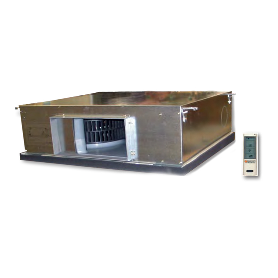
INTRODUCTION INTRODUCTION General The new DLS DC INVERTER split unit range comprises the following RC (heat pump) models: • DLS 18 • DLS 24 • DLS 30 • DLS 36 • DLS 43 Remote control compatibility The units are compatible with remote controls RC3, RC4, RC7, RC8 Inverter description Unlike standard units (fix RPM) that are selected according to their nominal capacity to overcome the maximum required load, DC Inverter units can be selected to a smaller... - Page 5 INTRODUCTION • Monitoring software (PC port for high level service). • Cooling operation at outdoor temperature down to -10°C. • Heating operation at outdoor temperature down to -15°C. • Up to 100Pa External static pressure (most units). Indoor Unit 1.3.1 The DLS DCI indoor unit is a low silhouette ducted unit, and can be easily fitted to many type of residential and commercials applications.
-
Page 6: Tubing Connections
INTRODUCTION • Fan grill air outlet. • Service valves” flare” type connection. • Service ports for high/ low pressure measurement. • Interconnecting wiring terminal blocks. Tubing Connections Flare type-interconnecting tubing to be produced on site. Units can be installed with 70-meter pipe length and 30 meter height difference without oil traps. -
Page 7: Indoor Units
1.11 Matching Table INTRODUCTION 1.11.1 R410A 1.10 Matching Table INDOOR UNITS OUTDOOR UNITS INDOOR UNITS MODEL DLS 18 DCI DLS 21 DCI DLS 24 DCI DLS 30 DCI REFRIGER OUTDOOR MODEL DLS 18 DLS 24 DLS 30 DLS 36 DLS 43 √... -
Page 8: Product Data Sheet
PRODUCT DATA SHEET PRODUCT DATA SHEET DLS 18 DCI Model Indoor Unit DLS 18 DCI R410A AW Model Outdoor Unit AWAU-YBDE018-H11 Installation Method of Pipe Flared Heating Characteristics Units Cooling Average Warmer Capacity 5.0 (2.3÷5.9) 5.6 (1.9÷7.5) Pdesign SEER / SCOP... - Page 9 PRODUCT DATA SHEET DLS 24 DCI Model Indoor Unit DLS 24 DCI R410A AW Model Outdoor Unit AWAU-YBDE024-H11 Installation Method of Pipe Flared Heating Characteristics Units Cooling Average Warmer Capacity 6.8 (1.7÷7.4) 7.6 (1.8÷8.5) Pdesign SEER / SCOP Energy efficiency class Annual energy consumption 1,217 4,433...
- Page 10 PRODUCT DATA SHEET DLS 30 DCI Model Indoor Unit DLS 30 DCI R410A AW Model Outdoor Unit AWAU-YBDE030-H11 Installation Method of Pipe Flared Heating Characteristics Units Cooling Average Warmer Capacity 7.5 (2.8÷8.4) 8.6 (2.8÷9.4) Pdesign SEER / SCOP Energy efficiency class Annual energy consumption 1,450 4,955...
- Page 11 PRODUCT DATA SHEET DLS 36 DCI 1PH Model Indoor Unit DLS 36 DCI R410A AW Model Outdoor Unit AWAU-YBD036-H11 Installation Method of Pipe Flared Heating Characteristics Units Cooling Average Warmer Pdesign 10.2 10.2 SEER / SCOP Energy efficiency class Annual energy consumption 1,658 6,014 2,985...
- Page 12 PRODUCT DATA SHEET DLS 36 DCI 3PH Model Indoor Unit DLS 36 DCI R410A AW Model Outdoor Unit AWAU-YAD036-H13 Installation Method of Pipe Flared Heating Characteristics Units Cooling Average Warmer Pdesign 10.0 11.2 11.2 SEER / SCOP Energy efficiency class Annual energy consumption 2,125 6,527...
- Page 13 PRODUCT DATA SHEET DLS 43 DCI 3PH Model Indoor Unit DLS 43 DCI R410A AW Model Outdoor Unit AWAU-YAD042-H13 Installation Method of Pipe Flared Characteristics Units Cooling Heating Btu/hr 42,650(16,000~49,500) 45,000(16,000~54,600) Capacity - Nominal (Minimum~ Maximum) 12.5 (4.5~14.0) 14.0 (4.5~16.0) Power Input –...
- Page 14 PRODUCT DATA SHEET DLS 43 DCI 1 PH DLS 43 DCI Model Indoor Unit YBD 042 H11 Model Outdoor Unit DUCTED Installation Method Characteristics Units Cooling Heating Btu/hr 42,650 (15,350-49,470) 47,770 (15,350-54,590) Capacity - Nominal (Minimum ~ Maximum) 12.5 (4.5-14.5) 14.0 (4.5-16.0) Power Input - Nominal (Minimum ~ Maximum) 3,730 (1,400-4,850)
-
Page 15: Rating Conditions
RATING CONDITIONS RATING CONDITIONS Standard conditions in accordance with ISO 5151 and ISO 13253 (for ducted units) and EN 14511. Cooling: Indoor: C DB 19 C WB Outdoor: 35 C DB Heating: Indoor: C DB Outdoor: 7 C DB 6 C WB Operating Limits Indoor... -
Page 16: Outline Dimensions
OUTLINE DIMENSIONS OUTLINE DIMENSIONS Indoor Unit: DLS 18 / 24 / 30 / 36 / 43 DCI Model DLS 18, 24, 30 790 653 749 162 242 101 DLS 36, 43 854 715 815 282 131 SM DLSDCI 3-A.1 GB... - Page 17 OUTLINE DIMENSIONS Outdoor Unit: YBDE018 / 024 Outdoor Unit: YBDE030 תאור השינוי תאריך הודעת שינוי הוצאה שרטט בקר תיאור החלק באם לא צויין אחרת, כל המידות במ"מ MATERIAL & FINISH חומר וגמר לפני הצביעה Draw By Check By Description Date E.C.O.
- Page 18 OUTLINE DIMENSIONS Outdoor Unit: YBDE036-H11 Outdoor Unit: YAD036/042-H13 , YBD042-H11 תאור השינוי תאריך הודעת שינוי הוצאה שרטט בקר באם לא צויין אחרת, כל המידות במ"מ תיאור החלק MATERIAL & FINISH חומר וגמר לפני הצביעה Draw By Check By Description Date E.C.O.
-
Page 19: Performance Data & Pressure Curves
PERFORMANCE DATA & PRESSURE CURVES PERFORMANCE DATA & PRESSURE CURVES DLS 18 DCI - H11 5.1.1 Cooling Capacity (kW) ID COIL ENTERING AIR DB/WB TEMPERATURE [ OD COIL ENTERING AIR DB DATA 22/15 24/17 27/19 29/21 32/23 TEMPERATURE [ 80 - 110 % of nominal... - Page 20 PERFORMANCE DATA & PRESSURE CURVES 5.1.2 Heating Capacity ID COIL ENTERING AIR DB TEMPERATURE [°C] OD COIL ENTERING AIR DB/WB DATA TEMPERATURE [°C] 3.56 3.32 3.07 -15/-16 0.88 0.97 1.05 3.97 3.72 3.47 -10/-12 1.06 1.15 1.23 4.27 4.02 3.77 -7/-8 1.19 1.28...
- Page 21 PERFORMANCE DATA & PRESSURE CURVES 5.1.3 Pressure Curves Cooling – Technician Mode) 5.1.3.1 Cooling DNG 50 DCI - Cooling Test Mode Curves Suction Pressure VS.Outdoor Temp'. 1400 Indoor DB/WB 1300 Temp. 1200 1100 22/15 1000 24/17 27/19 29/21 32/23 Outdoor DB Temperature[ºC] Discharge Pressure VS.
- Page 22 PERFORMANCE DATA & PRESSURE CURVES 5.1.3.2 Heating Suction Pressure VS.Outdoor Temp'. 1100 Indoor DB 1000 Temp'. Outdoor WB Temperature[ºC] Discharge Pressure VS. Outdoor Temp'. 3900 Indoor DB 3650 Temp'. 3400 3150 2900 2650 2400 2150 1900 1650 1400 Outdoor WB Temperature[ºC] 10.00 9.50 9.00...
- Page 23 PERFORMANCE DATA & PRESSURE CURVES DLS 24 DCI - H11 5.2.1 Cooling Capacity (kW) ID COIL ENTERING AIR DB/WB TEMPERATURE [C0] OD COIL ENTERING AIR DB TEMPERATURE [C0] DATA 22/15 24/17 27/19 29/21 32/23 80 - 110 % of nominal -10 - 20 80 - 105 % of nominal (protection range)
- Page 24 PERFORMANCE DATA & PRESSURE CURVES 5.2.2 Heating Capacity ID COIL ENTERING AIR DB TEMPERATURE [°C] OD COIL ENTERING AIR DB/WB TEMPERATURE [°C] DATA 4.84 4.50 4.16 -15/-16 1.25 1.38 1.50 5.38 5.05 4.71 -10/-12 1.50 1.63 1.76 5.80 5.46 5.12 -7/-8 1.70 1.82...
- Page 25 PERFORMANCE DATA & PRESSURE CURVES 5.2.3 Pressure Curves Cooling – Technician Mode) 5.2.3.1 Cooling DNG 72 DCI - Cooling Test Mode Curves Suction Pressure VS.Outdoor Temp'. 1400 1300 Indoor DB/WB 1200 Temp. 1100 22/15 1000 24/17 27/19 29/21 32/23 Outdoor DB Temperature [ºC] Discharge Pressure VS.
- Page 26 PERFORMANCE DATA & PRESSURE CURVES 5.2.3.2 Heating Suction Pressure VS.Outdoor Temp'. 1300 Indoor DB 1200 1100 Temp'. 1000 Outdoor WB Temperature[ºC] Discharge Pressure VS. Outdoor Temp'. 3950 3700 Indoor DB 3450 Temp'. 3200 2950 2700 2450 2200 1950 1700 1450 1200 Outdoor WB Temperature[ºC] 12.00...
- Page 27 PERFORMANCE DATA & PRESSURE CURVES DLS 30 DCI - H11 5.3.1 Cooling Capacity (kW) ID COIL ENTERING AIR DB/WB TEMPERATURE [ OD COIL ENTERING AIR DB DATA 22/15 24/17 27/19 29/21 32/23 TEMPERATURE [ 80 - 110 % of nominal -10 - 20 80 - 105 % of nominal (protection range)
- Page 28 PERFORMANCE DATA & PRESSURE CURVES 5.3.2 Heating Capacity ID COIL ENTERING AIR DB TEMPERATURE [°C] OD COIL ENTERING AIR DB/WB DATA TEMPERATURE [°C] 5.47 5.09 4.71 -15/-16 1.44 1.59 1.73 6.09 5.71 5.33 -10/-12 1.74 1.88 2.03 6.56 6.17 5.79 -7/-8 1.96 2.10...
- Page 29 PERFORMANCE DATA & PRESSURE CURVES 5.3.3 Pressure Curves Cooling – Technician Mode) 5.3.3.1 Cooling DNG 80DCI - Cooling Test Mode Curves Suction Pressure VS.Outdoor Temp'. 1400 Indoor DB/WB 1300 Temp. 1200 22/15 1100 24/17 1000 27/19 29/21 32/23 Outdoor DB Temperature [ºC] Discharge Pressure VS.
- Page 30 PERFORMANCE DATA & PRESSURE CURVES 5.3.3.2 Heating Suction Pressure VS.Outdoor Temp'. 1300 1200 Indoor DB 1100 Temp'. 1000 Outdoor WB Temperature[ºC] Discharge Pressure VS. Outdoor Temp'. 3950 3700 Indoor DB 3450 Temp'. 3200 2950 2700 2450 2200 1950 1700 1450 1200 Outdoor WB Temperature[ºC] 15.00...
- Page 31 PERFORMANCE DATA & PRESSURE CURVES DLS 36 DCI - H11 5.4.1 Cooling Capacity (kW) ID COIL ENTERING AIR DB/WB TEMPERATURE [C0] OD COIL ENTERING AIR DB TEMPERATURE [C0] DATA 22/15 24/17 27/19 29/21 32/23 80 - 110 % of nominal -10 - 20 80 - 105 % of nominal (protection range)
- Page 32 PERFORMANCE DATA & PRESSURE CURVES 5.4.2 Heating Capacity ID COIL ENTERING AIR DB TEMPERATURE [°C] OD COIL ENTERING AIR DB/WB TEMPERATURE [°C] DATA 6.49 6.04 5.58 -15/-16 1.62 1.79 1.95 7.23 6.77 6.32 -10/-12 1.95 2.12 2.28 7.78 7.32 6.87 -7/-8 2.20 2.37...
- Page 33 PERFORMANCE DATA & PRESSURE CURVES 5.4.3 Pressure Curves Cooling – Technician Mode) PERFORMANCE DATA & PRESSURE CURVES 5.4.3.1 Cooling 5.5.5 Pressure Curves Cooling – Technician Mode) Suction Pressure - Cooling (Technician Mode) Suction Pressure - Cooling (Technician Mode) 1400 1400 1300 1300 1200...
- Page 34 PERFORMANCE DATA & PRESSURE CURVES PERFORMANCE DATA & PRESSURE CURVES 5.4.3.2 Heating 5.5.6 Pressure Curves Heating – Technician Mode) Suction Pressure - Heating (Technician Mode) 1300 1200 1100 1000 Outdoor WB Temperature [°C] Discharge Pressure - Heating (Technician Mode) 4000 3750 3500 3250...
- Page 35 PERFORMANCE DATA & PRESSURE CURVES DLS 36 DCI - H13 5.5.1 Cooling Capacity (kW) ID COIL ENTERING AIR DB/WB TEMPERATURE [C0] OD COIL ENTERING AIR DB TEMPERATURE [C0] DATA 22/15 24/17 27/19 29/21 32/23 80 - 110 % of nominal -10 - 20 80 - 105 % of nominal (protection range)
- Page 36 PERFORMANCE DATA & PRESSURE CURVES 5.5.2 Heating Capacity ID COIL ENTERING AIR DB TEMPERATURE [°C] OD COIL ENTERING AIR DB/WB TEMPERATURE [°C] DATA 7.13 6.63 6.13 -15/-16 1.95 2.15 2.35 7.94 7.44 6.94 -10/-12 2.35 2.55 2.75 8.54 8.04 7.54 -7/-8 2.65 2.85...
- Page 37 PERFORMANCE DATA & PRESSURE CURVES 5.5.3 Pressure Curves Cooling – Technician Mode) 5.5.3.1 Cooling Suction Pressure - Cooling (Technician Mode) 1400 1300 1200 32/23 1100 29/21 1000 27/19 24/17 22/15 Outdoor DB Temperature [°C] Discharge Pressure - Cooling (Technician Mode) 4000 3750 3500...
- Page 38 PERFORMANCE DATA & PRESSURE CURVES 5.5.3.2 Heating Suction Pressure - Heating (Technician Mode) 1300 1200 1100 1000 Outdoor WB Temperature [°C] Discharge Pressure - Heating (Technician Mode) 4000 3750 3500 3250 3000 2750 2500 2250 2000 1750 1500 1250 1000 Outdoor WB Temperature [°C] 5-20 SM DLSDCI 3-A.1 GB...
- Page 39 PERFORMANCE DATA & PRESSURE CURVES DLS 43 DCI - H11 5.6.1 Cooling Capacity (kW) ID COIL ENTERING AIR DB/WB TEMPERATURE [C0] OD COIL ENTERING AIR DB TEMPERATURE [C0] DATA 22/15 24/17 27/19 29/21 32/23 80 - 110 % of nominal -10 - 20 80 - 105 % of nominal (protection range)
- Page 40 PERFORMANCE DATA & PRESSURE CURVES 5.6.2 Heating Capacity ID COIL ENTERING AIR DB TEMPERATURE [°C] OD COIL ENTERING AIR DB/WB TEMPERATURE [°C] DATA 8.91 8.29 7.67 -15/-16 2.58 2.84 3.11 9.92 9.30 8.67 -10/-12 3.11 3.37 3.64 10.68 10.05 9.43 -7/-8 3.51 3.77...
- Page 41 OD COIL ENTERING AIR DB TEMPERATURE [C0] Suction Pressure PERFORMANCE DATA & PRESSURE CURVES 22/15 620.3 752.0 781.3 807.02 830.0 854.7 382.5 ID COIL ENTERING AIR 24/17 658.3 798.0 829.1 856.39 880.7 907.0 405.9 DB/WB TEMPERATURE 27/19 715.22 867.0 900.8 930.45 956.91 985.4...
- Page 42 OD COIL ENTERING AIR WB TEMPERATURE [C0] Suction Pressure PERFORMANCE DATA & PRESSURE CURVES ID COIL ENTERING AIR 703.00 302.37 352.50 410.94 517.26 580.33 788.71 884.88 DB/WB TEMPERATURE 306.43 416.46 712.44 357.24 524.21 588.13 799.31 896.77 5.6.3.2 Heating 714.33 307.24 358.18 417.57 525.60...
- Page 43 PERFORMANCE DATA & PRESSURE CURVES DLS 43 DCI - H13 5.7.1 Cooling Capacity (kW) ID COIL ENTERING AIR DB/WB TEMPERATURE [C0] OD COIL ENTERING AIR DB TEMPERATURE [C0] DATA 22/15 24/17 27/19 29/21 32/23 80 - 110 % of nominal -10 - 20 80 - 105 % of nominal (protection range)
- Page 44 PERFORMANCE DATA & PRESSURE CURVES 5.7.2 Heating Capacity ID COIL ENTERING AIR DB TEMPERATURE [°C] OD COIL ENTERING AIR DB/WB TEMPERATURE [°C] DATA 8.91 8.29 7.67 -15/-16 2.58 2.84 3.11 9.92 9.30 8.67 -10/-12 3.11 3.37 3.64 10.68 10.05 9.43 -7/-8 3.51 3.77...
- Page 45 PERFORMANCE DATA & PRESSURE CURVES PERFORMANCE DATA & PRESSURE CURVES 5.7.3 Pressure Curves Cooling – Technician Mode) 5.6.5 Pressure Curves Cooling – Technician Mode) 5.7.3.1 Cooling Suction Pressure - Cooling (Technician Mode) 1400 1300 1200 32/23 1100 29/21 1000 27/19 24/17 22/15 Outdoor DB Temperature [°C]...
- Page 46 PERFORMANCE DATA & PRESSURE CURVES PERFORMANCE DATA & PRESSURE CURVES 5.7.3.2 Heating 5.6.6 Pressure Curves Heating – Technician Mode) Suction Pressure - Heating (Technician Mode) 1200 1100 1000 Outdoor WB Temperature [°C] Discharge Pressure - Heating (Technician Mode) 3950 3700 3450 3200 2950...
- Page 47 PERFORMANCE DATA & PRESSURE CURVES PERFORMANCE DATA & PRESSURE CURVES PERFORMANCE DATA & PRESSURE CURVES Capacity Correction Factor for Tubing Length Capacity Correction Factor for Tubing Length Capacity Correction Factor for Tubing Length 5.7.1 Cooling 5.8.1 Cooling 5.7.1 Cooling 1.05 1.05 1.00 1.00...
- Page 48 PERFORMANCE DATA & PRESSURE CURVES PERFORMANCE DATA & PRESSURE CURVES Pressure Correction Factor for Tubing Length Pressure Correction Factor for Tubing Length 5.9.1 Cooling PERFORMANCE DATA & PRESSURE CURVES 5.8.1 Cooling Pressure Correction Factor for Tubing Length Pressure vs Tubing Lenght (COOLING) 5.8.1 Cooling 1.02...
- Page 49 3.85 – Wet Bulb Temp., ( C) – Dry Bulb Temp., ( 15.43 14.8 10/9 – Indoor PERFORMANCE DATA & PRESSURE CURVES 4.08 – Outdoor 16.24 15.6 5.10 Capacity Correction Factors (Cooling) 15/12 4.31 5.6.2 Capacity Correction Factors (Cooling) 15-24 85 - 105 % o 80 - 120 % o (Protection Range)
- Page 50 PERFORMANCE DATA & PRESSURE CURVES 5.12 Calculation Example Outdoor unit YBD042-H11 Indoor unit DLS 43 DCI Operation Mode Cooling Mode Conditions Indoor 22°CDB/15°WB Conditions Oudoor 30°CDB Tubing length Cooling Capacity calculation: Total Cooling Capacity (TC) [KW] = Capacity in conditions table x F Cooling Capacity in table [KW] Tubing Length Factor (F Corrected Capacity [KW]...
-
Page 51: Airflow Curves
1013 AIRFLOW CURVES 1.98235E-05 47.4 1107 1123 19.82351 1000 37.4 1085 12.68704 28.7 Model: DLS 18 DCI 1045 8.375432 22.5 1013 Airflow Vs. External Static Pressure Turbo Speed High Speed Medium Speed Low Speed Nominal System Resistance Max System Curve Operating range... - Page 52 28.17719 1550 98.0 1400 1418 1185 1509 26.38863 1500 4.9993E-05 1460 1372 1146 80.0 1265 1356 1130 1.17283E-05 72.0 1200 1443 1460 AIRFLOW CURVES 22.98743 1400 60.5 1100 1334 1116 1420 1292 1082 16.88872 1200 50.0 1000 1375 1259 1057 11.72828 1000 36.1...
- Page 53 1936 41.48097 1800 91.6 1600 1453 1800 1264 1876 39.20848 1750 3.57797E-05 1745 1429 1243 90.0 1586 1828 1411 1.28028E-05 70.1 1400 1700 1700 1227 1762 1388 32.77509 1600 60.5 1300 AIRFLOW CURVES 1639 1207 1720 25.09343 1400 51.5 1200 1368 AIRFLOW CURVES 1600...
-
Page 54: Rating Conditions
AIRFLOW CURVES DLS UNITS RANGE AIR FLOW CORRECTION FACTORS (at nominal rating conditions — Test mode). Air Flow Rate [% of nominal] 100% 0.88 0.91 0.94 0.97 Cooling 0.78 0.84 0.89 0.95 0.95 0.97 0.98 0.99 1.07 1.05 1.03 1.02 Heating 0.90 0.92... -
Page 55: Sound Level Characteristics
SOUND LEVEL CHARACTERISTICS OPERATING CURVES SOUND LEVEL CHARACTERISTICS SOUND LEVEL CHARACTERISTICS Indoor Units Test Scheme Indoor Units SOUND LEVEL CHARACTERISTICS SOUND LEVEL CHARACTERISTICS Sound Pressure Level 2m duct in 2m duct in supply air area return air area static pressure Unit test point 1.4m... - Page 56 SOUND LEVEL CHARACTERISTICS SOUND LEVEL CHARACTERISTICS SOUND LEVEL CHARACTERISTICS DLS 24 DLS 30 DLS 24 DLS 24 DLS 30 DLS 30 DLS 36 DLS 43 DNG 37 DNG 37 NC-70 NC-70 NC-60 NC-60 NC-50 NC-50 NC-40 NC-40 NC-30 NC-30 APPROXIMATE APPROXIMATE THRESHOLD OF THRESHOLD OF...
- Page 57 P.N. R410 Type: DNG INV 40 Background Noise,dB(A): 369.3/36.7 Test Mode SOUND LEVEL CHARACTERISTICS utdoor Octave Band Sound Pressure Level, dB mpr. Speed : Cool - 78 Hz ; EEV179; CTT 75 Heat -76 Hz; EEV334; CTT59 utdooor Fan Outdoor Units Drawing of microphone position Outdoor 1100/1100 1100/1100 Octave...
- Page 58 Center for Unit SOUND LEVEL CHARACTERISTICS Figure 2 Sound Pressure Level Spectrum ( Measured as Figure 2) YBD036 - H11 Cooling YBD 036 - H11 Heating GCD 036 DCR Cooling GCD 036 DCR Heating SOUND LEVEL CHARACTERISTICS SOUND LEVEL CHARACTERISTICS GC 36 DCI Cooling GC 36 DCI Heating YBD 042 - H11 Cooling...
- Page 59 SOUND LEVEL CHARACTERISTICS YAD 036/042 - H13Cooling YAD 036/042 - H13 Heating Noise spectrum & NC Curves Noise spectrum & NC Curves NC65 NC65 NC60 NC60 NC55 NC55 NC50 NC50 NC45 NC45 NC40 NC40 NC35 NC30 NC35 NC30 NC25 NC20 NC25 NC15 NC20...
-
Page 60: Electrical Data
ELECTRICAL DATA ELECTRICAL DATA Single Phase Units (DLS 18-30) MODEL DLS 18 DLS 24 DLS 30 Power Supply 1 PH ,220-240VAC ,50HZ Connected to Indoor or Outdoor Outdoor Maximum Current 45 A Inrush Current 15 A Starting Current Circuit Breaker 20 A Power Supply Wiring No х... -
Page 61: Wiring Diagrams
WIRING DIAGRAMS WIRING DIAGRAMS Indoor Unit: DLS 18 DCI Indoor Units: DLS 24/30 DCI SM DLSDCI 3-A.1 GB... - Page 62 WIRING DIAGRAMS Indoor Unit: DLS 36 DCI Indoor Unit: DLS 43 DCI LEGEND PUMP DIP SWITCH -BLACK -BROWN COMM1 RS485 -BLUE TO OUTDOOR -YELLOW/GREEN AC LOUVER COMM2 UNIT -GREY -VIOLET -WHITE -ORANGE -RED -CAPACITOR HIGH -FAN MOTOR S/HI -AMBIENT SENSOR (ROOM) IFAN -DEFROSTING SENSOR (IN) -WATER PUMP...
- Page 63 WIRING DIAGRAMS Outdoor Units: YBDE 018/024 - H11 YEL/GRN CHOCK OFAN COMP REVERSE COIL VALVE Optional P104 P106 P503 P501 P201 P202 P109 P105 P604 P804 P803 P801 P802 P108 P502 Outdoor Unit Controller CN802 FUSE CN801 FLASH P805 P601 MODEL P102 P602...
- Page 64 WIRING DIAGRAMS Outdoor Unit: YBD036 - H11 DANGER!! ATTENTION: HIGH DC VOLTAGE!! FOR INDOOR UNIT ELECTRICAL WIRING REFER TO INDOOR UNIT DIAGRAM DO NOT TOUCH WHILE LED'S ARE ON AND 3 MINUTE AFTER POWER OFF LINE FILTER POWER SUPPLY(BY INSTALLER): Chock 1PH/230VAC / 50Hz Coils...
- Page 65 WIRING DIAGRAMS Outdoor Unit: YBD042 - H11 ATTENTION: POWER SUPPLY(BY INSTALLER): DANGER!! HIGH DC VOLTAGE!! FOR INDOOR UNIT 1PH 230VAC / 50Hz 4HP - 3x 4mm² DO NOT TOUCH WHILE LED'S ELECTRICAL WIRING REFER 5HP - 3x 6mm² ARE ON AND 1 MINUTE AFTER 6HP - 3x 6mm²...
- Page 66 WIRING DIAGRAMS Outdoor Unit: YAD036/042 - H13 ATTENTION: POWER SUPPLY(BY INSTALLER): DANGER!! HIGH DC VOLTAGE!! FOR INDOOR UNIT 3PH/400VAC / 50Hz 5x 2.5mm² DO NOT TOUCH WHILE LED'S ELECTRICAL WIRING REFER ARE ON AND 1 MINUTE AFTER CABLE BETWEEN INDOOR AND POWER OFF TO INDOOR UNIT DIAGRAM OUTDOOR UNITS:...
- Page 67 WIRING DIAGRAMS 9.10 1PH UNITS POWER SUPPLY TO INDOOR (DLS 18) (5.0 kW )יחידת C N L Indoor Unit Power Supply Cable Outdoor Unit Interconnecting Cable (4x2.5mm Wireless Remote Control Display Unit Display Connector Power Breaker (*by installer) * The power breaker must be of type that disconnects all poles with 3 mm contact opening. ** Use shielded cable and connect the shield to earth point SM DLSDCI 3-A.1 GB...
- Page 68 WIRING DIAGRAMS 9.11 1PH UNITS POWER SUPPLY TO OUTDOOR (DLS 18,24) C N L Indoor Unit Power Supply Cable Main Power Breaker Outdoor Unit Interconnecting Cable (4x2.5mm Wireless Remote Control Display Unit Display Connector Power Breaker (*by installer) * The power breaker must be of type that disconnects all poles with 3 mm contact opening. ** Use shielded cable and connect the shield to earth point SM DLSDCI 3-A.1 GB...
- Page 69 WIRING DIAGRAMS 9.12 1PH UNITS POWER SUPPLY TO OUTDOOR (DLS 30) (8.0 kW )יחידת 4 x 2.5 " Indoor Unit Power Supply Cable Main Power Breaker Outdoor Unit Interconnecting Cable (4x2.5mm Wireless Remote Control Display Unit Display Connector Power Breaker (*by installer) * The power breaker must be of type that disconnects all poles with 3 mm contact opening.
- Page 70 WIRING DIAGRAMS 9.13 1PH UNITS POWER SUPPLY TO OUTDOOR (10.0, 12.5, 14.0 kW units) Indoor Unit Power Supply Cable Main Power Breaker Outdoor Unit Interconnecting cable (2x0.75mm Power Interconnecting Cable (3x1.5mm Wireless remote Control Display Unit Display Connector Power Breaker (*by installer) Control Cable** Sensor Wire with connector Room Temperature Sensor...
- Page 71 WIRING DIAGRAMS 9.14 1PH UNITS POWER SUPPLY TO OUTDOOR and INDOOR UNIT SEPARATELY (10.0, 12.5, 14.0 kW units) 1. Indoor Unit 2. Power Supply Cable 3. Main Power Breaker 4. Outdoor Unit 5. Interconnecting cable (2x0.75mm 6. Wireless remote Control 7.
- Page 72 WIRING DIAGRAMS 9.15 3PH UNITS POWER SUPPLY TO OUTDOOR UNIT L3 L2 Indoor Unit Power Supply Cable Main Power Breaker Outdoor Unit Interconnecting cable (2x0.75mm Power Interconnecting Cable (3x1.5mm Wireless remote Control Display Unit Display Connector Power Breaker (*by installer) Control Cable** Sensor Wire with connector Room Temperature Sensor...
- Page 73 WIRING DIAGRAMS 9.16 3PH UNITS POWER SUPPLY TO OUTDOOR and INDOOR UNIT SEPARATELY L3 L2 1. Indoor Unit 2. Power Supply Cable 3. Main Power Breaker 4. Outdoor Unit 5. Interconnecting cable (2x0.75mm 6. Wireless remote Control 7. Display Unit 8.
-
Page 74: Refrigeration Diagrams
REFRIGERATION DIAGRAMS REFRIGERATION DIAGRAMS REFRIGERATION DIAGRAMS REFRIGERATION DIAGRAMS 10.1 Heat Pump Models 10.1 Heat Pump Models 10.1.1 DLS 36 / DLS 43 (Optional) (Optional) Oil cappilary tube 2.5mmx0.6mmx1000mm Line accumulator Compressor separator (Optional) (Optional) Gas valve 4 Way valve Flared Connection Filter Liquid... -
Page 75: Tubing Connections
TUBING CONNECTIONS TUBING CONNECTIONS TUBE (Inch) ¼” ⅜” ½” ⅝” ¾” TORQUE (Nm) Flare Nuts 15-18 40-45 60-65 70-75 80-85 Valve Cap 13-20 13-20 18-25 18-25 40-50 Service Port Cap 11-13 11-13 11-13 11-13 11-13 Valve Protection Cap-end Refrigerant Valve Port (use Allen wrench to open/close) Valve Protection Cap Refrigerant Valve Service Port Cap... -
Page 76: Control System
CONTROL SYSTEM CONTROL SYSTEM 12.1 Abbreviations Abbreviation Definition Air Conditioner Building Management System Compressor Current Crankcase Heater COMP Compressor Compressor Top Temperature sensor DC Inverter DMSMP Dummy Multi Split multi Pipe – Control board E²PROM, EEP Erase Enable Programmable Read Only Memory Electronic Expansion Valve Heating Element Human Machine Interface... -
Page 77: Product Overview
CONTROL SYSTEM 12.2 Product Overview 12.2.1 Block Diagram Line Filter Compressor 230VAC Driver Inrush Control 400VAC (4-5HP Only) Speed AC Current DC Current Fault codes Inrush Driver Control Control ODU Controller OFAN Control Display OFAN IDU Controller Control Communication IFAN Temp. - Page 78 CONTROL SYSTEM 12.2.2 Controller overview 12.2.2.1 Main Controller Indoor Unit (DLS 36/43) Fuse 3.15A Indoor Fan Horizontal Louvers Pump Comm. To ODU Power Supply RCW Connection Display PCB Clock Swing Motor Room Sensor (RAT) DIP-SWITCHES Indoor Coil Sensor (ICT) M2L (PC Tool) Level IR Jumper Connection to Display Cable...
- Page 79 CONTROL SYSTEM 12.2.2.3 Display Board Display Display Board PCB Legend Name Plate Cooling LED Heating LED Push Button (Mode) Timer LED STBY LED Operation LED IR Receiver Buzzer TROUBLES 10. Display Port Connection 12.2.2.4 New Display Board CONTROL SYSTEM Legend 1.
- Page 80 CONTROL SYSTEM 12.2.3 Control Features 12.2.3.1 Compressor DC brush less and sensor less motor inverter driven compressor. 12.2.3.2 Compressor Drive DC inverter module to drive compressor. 12.2.3.3 Outdoor Fan DC brush less motor(s) drive the outdoor unit fan(s). 12.2.3.4 Reverse Valve set the direction of refrigerant flow in the system, thus setting the operation mode for cooling or heating.
- Page 81 Heating Element (Indoor) P – Sensor is acting only for protection. + - Sensor is active part of the control. CONTROL SYSTEM 12.2.3.9 Base Heater Heating element designed to melt any ice that is accumulated on the outdoor unit base 12.2.3.9 Base Heater during low heating operation.
- Page 82 CONTROL SYSTEM 12.3 General Operating Rules 12.3.1 Power up Sequence After Power up A/C must perform some initialization procedures. • Thermistors short/disconnect. • Compressor Driver communication connected and error codes if any. • Fans connected – check feedback. • EEPROM power up parameters uploads. •...
- Page 83 CONTROL SYSTEM 12.3.2 Communication with Indoor Unit 12.3.2.1 Communication Failures Definition 12.3.2.1.1 ‘Bad Communication’ fault The system keeps a balance of a good/bad communication packet ratio. When the ratio becomes high the system enters ‘Bad Communication’ fault. The system recovers from that fault when the ratio becomes small again. When in ‘Bad Communication’...
- Page 84 CONTROL SYSTEM The following combinations show the allowed and not allowed capacity group: Is it allowed capacity group? ODU Model Communication channel Indoor Capacity AB (GCD36 DCI) Single AE (4HP DCI 3-Phase) Single AF (5HP DCI 3-Phase) Single AG (6HP DCI 3-Phase Single AO (YBD042/5HP DCI) Single...
- Page 85 CONTROL SYSTEM 12.3.4.3 System operation whenever a thermistor fault occurs ODU Mode H/NH √ √ √ √ √ √ Normal H/NH √ Stop Comp H/NH √ √ √ √ √ √ Normal H/NH √ Stop Comp H/NH √ √ √ √...
- Page 86 CONTROL SYSTEM NLOAD limits as a function of power shedding: Mode Power Shedding OFF Power Shedding ON Cooling No limit Nominal Cooling Heating No limit Nominal heating 12.4.2 Indoor Fan Control 12.4.2.1 Indoor fan control - FAN Mode • When T/H/M/L speed is set by user, IFAN will work in constant requested speed. •...
- Page 87 CONTROL SYSTEM 12.4.2.2 Indoor fan control - Cool Mode • When T/H/M/L speed is set by user, IFAN will work in constant requested speed. • When Auto-Fan speed is set by user, IFAN speed will be set according to LOAD(n) as in the following graph: IFAN Speed IFTURBO...
-
Page 88: Control Functions
CONTROL SYSTEM 12.4.3 Cooling Mode 12.4.3.1 Cooling Mode – General Mode Definition Mode: COOL, AUTO (at Cooling) Temp: Selected desired temperature. Fan: LOW, MED, HIGH, TURBO, AUTO. Timer: I-FEEL: ON or OFF Room Temperature, RT, is detected by: RAT in normal operation, or RCT (R/C sensor) in I-FEEL mode. - Page 89 CONTROL SYSTEM 12.4.4 Heating Mode 12.4.4.1 Heating - General Mode Definition Mode: HEAT, AUTO (at heating) Temp: Selected desired temperature Fan: LOW, MED, HIGH, TURBO, AUTO. Timer: Any I-FEEL: ON or OFF Room Temperature, RT, is detected by: RAT in normal operation, or RCT (R/C sensor) in I-FEEL mode.
- Page 90 CONTROL SYSTEM 12.4.4.4 Temperature Compensation A compensation value of 2-4 degrees is reduced from room temperature reading (except when in I-Feel mode), to compensate for temperature difference between high and low areas in the heated room, and for coil heat radiation on room thermistor.
-
Page 91: Control Function
CONTROL SYSTEM 12.4.6 Dry Mode 12.4.6.1 DRY - General Mode Definition Mode: Temp: Selected desired temperature Fan: LOW (automatically selected by software) Timer: I-FEEL: ON or OFF 12.4.6.2 Control function COMP Operation In general – the operation is set by the NLOAD calculation in indoor unit side. Other rules are according to section 12.5.1. -
Page 92: Sleep Mode
CONTROL SYSTEM 12.4.7 Sleep Mode 12.4.7.1 Sleep Mode - General Mode Definition Mode: Temp: Selected desired temperature IFan: Timer: See below I-FEEL: ON or OFF 12.4.7.2 Control function o The Sleep mode is activated by using the SLEEP button on the R/C. In Sleep Mode, the unit will automatically adjust the SPT to turn up/down the room temperature (RT) gradually to provide maximum comfort for the sleeping user. - Page 93 CONTROL SYSTEM 12.4.9 Indoor Units Operation when Indoor Unit Mode is Different than Outdoor Unit Mode • Open louvers according to user selection. • Indoor fan is forced to OFF. 12.4.10 Indoor Unit Dry Contact 12.4.10.1 System with SW up to 2013: Indoor unit Dry contact has two alternative functions that are selected by J9 (Dip-Switch).
-
Page 94: Run Mode
CONTROL SYSTEM 12.5 Run Mode Run mode is the default operation mode of the system. This is the standard operation mode that is active in field application (at customer site). System can go from run mode to other operation modes through keyboard or serial ports. 12.5.1 Mode Setting Thermal mode defines the ODU operation mode. - Page 95 CONTROL SYSTEM 12.5.2.1 Compressor Min On/Off time Compressor minimum ON and OFF time is 3 minutes except during protections. 12.5.2.2 Compressor Startup When started, compressor speed reaches certain level (usually 30÷40 RPS) and will not go below that during the first 5 minutes except when compressor is forced OFF.
- Page 96 CONTROL SYSTEM 12.5.2.9 Compressor taget frequency During normal operation (excluding protections) the compressor target frequency is set according to the ODU NLOAD number received from the indoor unit. ODU NLOAD Target Frequency [Hz] 0 < ODU NLOAD ≤ MinFreq MinFreq >MinFreq Linear relation between Min and Max freq. 12.5.3 EEV Control 12.5.3.1 EEV General Rules...
- Page 97 CONTROL SYSTEM 12.5.3.6 EEV correction definition(EEVCV The EEV correction value is determined according to the operation mode, the actual compressor speed and indoor/outdoor conditions. The correction value is targeting towrds optimal behavior of the system. The following table describes the closed loop control type (EEV correction): Main EEV Mode Target CTT...
- Page 98 CONTROL SYSTEM 12.6 Thermodynamic Protections TROUBLESHOOTING 12.6.1 IDU Protections 12.6.5 Condensate Water over Flow Protection 12.6.1.1 Condensate Water over Flow Protection Each of the pins P1, P2, P3 can have two options: Each of the pins P1, P2, P3 can have two options: 1 –...
- Page 99 CONTROL SYSTEM Protection Status General Description Normal No protection Hz Up Compressor frequency is allowed to increase slowly Stop Rise Compressor frequency is not allowed to rise Hz Down 1 Compressor frequency is reduce Hz Down 2 Compressor frequency is reduce Stop Compressor Compressor is stopped Each protection has protection status.
- Page 100 CONTROL SYSTEM 12.6.2.3 Total Protection Level Definition The total protection level is defined by the higher level of protection received. 12.6.3 Deicing 12.6.3.1 Deicing Starting Conditions 12.6.4.1 Deicing Starting Conditions Deicing operation will start when either one of the following conditions exist: Case 1: OCT is 8 degree lower then the ambiant temp and the minimum time from the last deicer is passed. Case 2: OCT is 12 degree lower then the ambiant temp and 30 minutes from the last deicer wa passed.
- Page 101 CONTROL SYSTEM 12.6.4 High/Low Pressure Protection Whenever high or low pressure accures in the system which extend beind the system pre-defined limits, the high and low pressure switchs turns on (short) and stops the compressor until these limits are redrawn. Fault code error 8 (HPS) or 9 (LPS) will be shown until compressor will resume operation.
- Page 102 CONTROL SYSTEM 12.8.3 Menus 12.8.3.1 Main Menu Mode (Cl/Ht/Sb) Technician Test (tt) Technician Test Cool (PtC) Technician Test Heat (PtH) Charge Test Cool (CtC) Charge Test Heat (CtH) Installation Test (it) (Multi Only) Number of IDU`s Begin test Test Result Matrix Table Test Result Problem Correction Diagnostics (dia)
- Page 103 CONTROL SYSTEM Notes The default presentation will be the mode of the unit (Cl/Ht/Sb). In diagnostics menu, xx means failure code. Only the last active (operative) failure code will be shown, if there is no active failure a “-“sign will be shown (the faults Numbers are the one shown in the single split table).
- Page 104 Pressing select and escape buttons together when in RST for more than 5 seconds will restore only the parameters of the factory settings. Acknowledge for restored parameters CONTROL SYSTEM will be indicated by blinking RST for 3 seconds. 12.8.3.2 Status (Sub Menu) 12.8.3.2 Status (Sub Menu) 12.8.3.2 Status (Sub Menu)
- Page 105 (Multi Only) Model -B (Multi Only) Model -C CONTROL SYSTEM (Multi Only) Model -D (Multi Only) Model -E Operation Mode OFAN Up OFAN Down Speed RGT-A (Multi Only) RGT-B (Multi Only) RGT-C (Multi Only) RGT-D (Multi Only) RGT-E (Multi Only) RLT-A (Multi Only) RLT-B...
- Page 106 CONTROL SYSTEM 12.8.4 Technician Perpherial Test (TPT) Technician Peripheral test mode designed especially for Technician personal to provide ability to test peripherals such as OFAN, EEV, RV, COMP, etc. Each item is operated directly so no software logic can deny the operation. 12.8.4.1 General Rules Entering TPT –...
- Page 107 CONTROL SYSTEM 12.8.4.3 Pump Down Test procedure Pump Down is used to evacuate the refrigerant back to the ODU in case of need to dis-connect the indoor unit or the inter-connecting piping for repair. Start the operation by navigating the HMI. A/C will start operate.
- Page 108 CONTROL SYSTEM 12.8.4.9 Gas Block Test procedure This test is used for technician to check the blockage within the system. The test is operates in heat mode and the technician should close the liquid valve manually. Start the operation by navigating the HMI. Note - The test is not operable when OAT<5°C.
- Page 109 CONTROL SYSTEM 12.9.2.2 Compensation Jumper/DIP – J2 Position Status Description Open (Disconnected) Compensation deactivated Close (Shorted) Compensation activated (Default) Used for height compenstation in heat mode 12.9.2.3 Family selection Jumper/DIP – J3, J4, J5, J11 Family Name DLS 4-5 HP EMD 4-5 HP 12.9.2.4 Model selection Jumper/DIP –...
- Page 110 CONTROL SYSTEM 12.9.3.2 ODU Model Selection Jumper/DIP – J2, J3, J4, J5, J6, J7 ODU Model M (DCI 100 / INV40) N (DCI 125 / INV50) AB (DCI 100 C.R / INV38) AE (DCI100 3PH / INV40T) AF (DCI125 3PH / INV50T) AG (DCI140 3PH / INV60T) AO (DCI 125 1-Phase Driver) AP (DCI 140 1-Phase Driver)
- Page 111 CONTROL SYSTEM YBDE 018-H11 (OU7-22 DCI) AS ON YBDE 024-H11 (OU7-30 DCI) YBDE 030-H11 (OU8-35 DCI) AU ON YBD036-H11 (4HP DCR) AB ON YAD036-H13 (4HP 3PH) AE ON YAD042-H13 (5HP 3PH) AF ON YAD060-H13 (6HP 3PH) AG ON YAD042-H11 (5HP 1-Phase) AO ON YBD060-H11 (6HP 1-Phase) AP ON...
- Page 112 CONTROL SYSTEM 12.9.5 Remote Control DIP Switch Settings SETTING SWITCH STATUS DEFINITION RC4 / RC4i / RC7 NO. 1 NO. 2 NO. 3 NO. 4 RC - all modes of operation ST - COOL, FAN, DRY modes active HEAT COOL, FAN, DRY modes active Auto Mode, FAN modes active Temp.
-
Page 113: System Parameters
CONTROL SYSTEM 12.10 System Parameters 12.10.1 General Parameters for All Models Name Default Value Units MinOFFTime minute MinONTime minute DImin minute DImax minute TimeD minute DTmin minute minute CTMRUP minute minute second DEICT1 second DEICT2 second DEICT3 second °C DSTF OMTOH0 °C OMTOH1... - Page 114 CONTROL SYSTEM 12.10.2 ODU Model Dependent Parameters Parameter Name Range MinFreqC 0-127 MaxFreqC 0-127 MinFreqH 0-127 MaxFreqH 0-127 DeicerFreq 0-127 Step1Freq 0-127 Step2Freq 0-127 Step3Freq 0-127 Step4Freq 0-127 Step1Time Step2Time Step3Time Step4Time NightRPS 0-110 OFMinRPMC 0-130 *10RPM OFMinRPMH 0-130 *10RPM OFMaxRPMC 0-130 *10RPM...
- Page 115 CONTROL SYSTEM Parameter Name Range HSTOH0 0 –110 °C HSTOH1 0 –110 °C HSTOH2 0 –110 °C HSTOH3 0 –110 °C HSTOH4 0 –110 °C HSTOH5 0 –110 °C ICTDef0 -23 – 8 °C ICTDef1 -23 – 8 °C ICTDef2 -23 –...
- Page 116 CONTROL SYSTEM 12.11 7-Segment Legend 7 7 -segments lege e nd SM DLSDCI 3-A.1 GB 12-41...
-
Page 117: Troubleshooting
TROUBLESHOOTING TROUBLESHOOTING 13.1 Precaution, Advise and Notice Items 13.1.1 High voltage in Indoor and Outdoor unit electrical assembly § Open the Outdoor unit controller assembly only after one minute from power off. § Whole controller assembly, including the wires, connected to the Outdoor unit may have the potential hazard voltage when power is on. - Page 118 TROUBLESHOOTING 13.2 General System Failures and Corrective Actions SYMPTOM / PROBABLE CORRECTIVE ACTION PROBLEM CAUSE Indoor unit Check supply voltage to main terminals L and N No Power supply with volt meter. Check all supply wiring to controller and terminals Miss-wiring according to wiring diagram Indoor unit power supply...
- Page 119 TROUBLESHOOTING SYMPTOM / PROBABLE CORRECTIVE ACTION PROBLEM CAUSE One indoor unit or more are operating in cool mode with no capacity, and the other units have water leaks/freezing communication Check and correct the communication wires problems wires of the connection indoor units are One indoor or more are switched...
- Page 120 TROUBLESHOOTING SYMPTOM / PROBABLE CORRECTIVE ACTION PROBLEM CAUSE Unit size not Check if the size chosen for the complete room(s) match the load load is enough or need bigger units Check if piping is installed correctly and proper Piping size not diameter size and total length is according to unit matching system specifications...
- Page 121 TROUBLESHOOTING SYMPTOM / PROBABLE CORRECTIVE ACTION PROBLEM CAUSE Check all according to above problem Check if HPS fault code (#8) is accruing Compressor stops many HP Switch frequently. If so, check the switch operation times during operation ( 13.5.14) Check if LPS fault code (#9) is accruing LP Switch frequently.
- Page 122 TROUBLESHOOTING 13.3 Checking the refrigeration system Checking system pressures and other thermodynamic measures should be done when system is in technician Mode where the system operates as in fixed settings. The performance curves given in this manual are given for unit performance in Technician mode when high indoor fan speed is selected.
- Page 123 TROUBLESHOOTING Problem OCT is shorted/disconnected CTT is shorted/disconnected HST is shorted/disconnected OAT is shorted/disconnected OMT is shorted/disconnected RGT is shorted/disconnected RLT is shorted/disconnected High pressure protection Low pressure protection No communication to Driver • Compressor IPM Fault • IPM Driver Pin •...
- Page 124 TROUBLESHOOTING 13.4.2 Outdoor unit diagnostics and corrective actions Fault Name Fault Description Corrective Action OCT short/disconnect CTT short/disconnect Thermistor not connected or HST short/disconnect damaged Check Thermistor (13.5.13) OAT short/disconnect OMT short/disconnect RGT short/disconnect RLT short/disconnect Normally no action is required Compressor stopped due to If the problem persists for more than twice High pressure protection...
- Page 125 TROUBLESHOOTING Fault Name Fault Description Corrective Action PFC Current sensor Driver fault Replace Compressor Driver Missing phase Check power supply lines Installation incorrect Phase order mismatch Switch between 2 supply lines Can occur during high current conditions. If problem persists, Check power supply to driver.
- Page 126 TROUBLESHOOTING Fault Name Fault Description Corrective Action System is performing out of its outdoor condition Check if indeed the conditions are Operation conditions are limitations: exceeded. If not, check OAT thermistor, if exceeded Cooling: >46°C , <-11°C. OK, check no obstructions to outdoor air Heating: >30°C , <-18°C.
- Page 127 TROUBLESHOOTING 13.4.4 Indoor unit diagnostics and corrective actions Fault Probable Cause Corrective Action Sensors not 1-4, Sensor failures Check Thermistor (13.5.13) connected or damaged Undefined IDU IDU is not a valid IDU jumper configuration is not correct Family/Model model or family IDU-ODU Check communication between indoor No Communication...
- Page 128 TROUBLESHOOTING Fault Probable Cause Corrective Action System is using EEPROM Not ROM parameters No action, unless special parameters are Updated and not EEPROM required for unit operation. parameters No action, unless special parameters are Bad EEPROM required for unit operation. IDU-ODU Check communication between indoor Bad Communication...
- Page 129 TROUBLESHOOTING TROUBLESHOOTING 13.5 Procedures for checking Main Parts 13.5 Procedures for checking Main Parts 13.5.1 Discharge DC Voltage 13.5.1 Discharge DC Voltage High voltage!!! Wait for DC voltage to be discharged before re touching any part of the driver to avoid electric shock.
- Page 130 TROUBLESHOOTING 13.5.4.3. YBD036-H11 In normal operation the red led in ON continuously and green led is blinking slow (1 time/sec). Even is that case, there can still be a Hardware problem that prevents the system to perform well or at all. If no other problem is found, replace the driver. 1) In case green and/or red leds are OFF (one or both): • Check power supply to driver connected well and no burn marks on wiring.
- Page 131 TROUBLESHOOTING 13.5.5 Checking PFC Chock coil 1) Check PFC chock connections – repair if needed. 2) Visually check to see any burn marks on the wires – replace the chock(s) if needed. 3) Disconnect the chock from the driver and check if the 2 ending wires of each chock are shorted (continuity check) –...
- Page 132 TROUBLESHOOTING 13.5.8.3 YBD 36/43 H11/H13 An Outdoor fan motor fault message may occur during very high winds outdoors that may stop the fan rotation for short periods. If so, need to relocate the outdoor unit to a more protected place from winds or install measure of air deflection in front of the fan outlets.
- Page 133 TROUBLESHOOTING 12.5.9 (3c) Feedbeck Voltage check 12.5.9 (3a) High Voltage check 13.5.9 Checking Compressor 1) Check Compressor connections - Repair if needed. 2) Check the resistance between the three phases – all three coil resistances should be the same: UNIT RESISTANCE YBD036 - H11 / INV38 0.788 Ω...
- Page 134 TROUBLESHOOTING 13.5.10 Checking Reverse Valve (RV) The RV has two parts, Solenoid and valve. 1) Disconnect the RV connector from the main board and operate the unit in heating mode, check the voltage between two pins of reverse valve connector on the controller, normal voltage is 230VAC - if no power supply to RV, replace outdoor main board.
- Page 135 TROUBLESHOOTING TROUBLESHOOTING TROUBLESHOOTING CTT (YBDE018-024-030), OAT, OCT, OMT, ICT, RAT, HST Chart R-T Table =10kΩ 25°C R-T Table β =10kΩ =3950K 25/85°C 25°C β 1000.0 =3977K 25/85°C 1000.0 100.0 100.0 10.0 10.0 Temperature [C] Temperature [C] CTT Chart (YAD/YBD 036-043) R-T Table =50kΩ...
- Page 136 TROUBLESHOOTING 13.5.13 Checking High Pressure Switch (HPS) 1) Disconnect HPS connector from the main board and check resistance between the 2 pins of the HPS connector – if shorted the HPS is OK, otherwise replace HPS. Replacing HPS - (14.1.10) 13.5.14 Checking Low Pressure Switch (LPS) 1) Disconnect LPS connector from the main board and check resistance between the 2 pins of the...
- Page 137 TROUBLESHOOTING Replacing Indoor Unit main board - (14.2.2) 13.5.16.2 YBD 018-030 1) Check voltage on the interconnection wiring – should be 22VDC±1VDC. If not: 2) Disconnect the wire cable from the connector on the IDU main board side and Check voltage on the IDU terminals “N”...
- Page 138 TROUBLESHOOTING 13.5.17 Checking Indoor Unit Fuse on Controller If the 3.15A fuse on the main Board is burnt check the fan or any other peripheral that can cause a short: 1) In case of a problematic peripheral - replace it. 2) In case no problematic peripheral replace the burnt fuse.
-
Page 139: Servicing
SERVICING TROUBLESHOOTING SERVICING 13.5 Procedures for checking Main Parts 14.1 Outdoor Unit DLS 36/43 13.5.1 Discharge DC Voltage High voltage!!! TURN OFF ALL POWER SOURCE BEFORE HANDLING THE UNIT Wait for DC voltage to be discharged before touching any part of the driver to Note: To reassemble perform the procedures in reverse. - Page 140 SERVICING 14.1.3 Removing side panel Remove the top cover as in above 14.1.2. Remove the 2 screws holding the electrical plastic cover and disconnect the power supply cords. Removing Side Panel Remove the 9 fixing screws and take out the side panel. Removing Electrical Cover Removing Electrical Cover Removing side panel...
- Page 141 SERVICING 14.1.6 Removing Outdoor Fan Motor 14.1.5. Remove the outdoor fan according to Disconnect the motor connector from the main board. Cut the nylon ties holding the motor cable. Remove the four (4) fixing screws for the motor. NOTES for re-assemble the motor: When mounting the motor, ensure the cables point downwards.
- Page 142 SERVICING 14.1.9 Removing Refrigeration parts Refrigeration parts: Expansion valve, Reversing valve, high pressure switch, etc. Remove the refrigerant from the unit by a pumping machine via the 2 valves. Note: open the valves gradually and leave them only partially open for as long as the refrigerant exerts from the unit.
- Page 143 SERVICING Disconnect Removing Compressor Insulation Removing Compressor 14.1.11 Removing Tubing Thermistors Remove the service front panel according to 14.1.1. Remove the side and top panels according to 14.1.2, 14.1.3 Check to ensure that LEDs and display board are OFF. Disconnect the thermistor connector from the main board.
- Page 144 SERVICING 14.1.13 Removing main board 14.1.13.1 YBD036 H11 / YAD036 H13 / YAD042 H13/YBD042 H11/YBD 060 H11 Remove the service front panel according to 14.1.1 Remove the controller cover by taking out the screw and lift upwards. Check to ensure that LEDs and display board are OFF.
- Page 145 SERVICING 14.1.14 Removing Electrical Assembly 14.1.14.1 YBD036 H11 1. Remove the service front panel according to 14.1.1. 1. Remove the service front panel according to 2. Remove the side and top panels according to 14.1.2. 14.1.1. 3. Check to ensure that LEDs and display board are 2.
- Page 146 SERVICING 14.1.15 Removing Driver Module 14.1.15.1 YBD036 H11 1. Remove the electrical assembly according to 14.1.14.2. 2. Remove the three (3) screws fixing the main board panel to the assembly and take the panel out. 3. Remove the two (2) screws fixing the terminal panel to the assembly and take the panel out.
- Page 147 SERVICING 14.1.16 Removing Chocks Coils 14.1.16.1 YBD036 H11 /YAD036 H13 /YAD042 H13 /YBD042 H11 /YBD 060 H11 1. Remove the chock coil wires from the chock terminal block. 2. Remove the 2 screws to release the chock coil from the partition. Removing Capacitor Board Removing Chocks Coils 14.1.17...
- Page 148 SERVICING 14.1.18.2 YBD042 H11 / YBD060 H11/YAD036-042 H13 1. Perform the driver module removal procedure in 14.1.15.3. 2. Open driver assembly cover. 3. Release all wires from the filter board. 4. Remove the screws fixing the filter panel to the driver assembly.
- Page 149 Removing Service Panel SERVICING 14.2.4 Removing Service Panel Remove the 2 fixing screws from the filter side, push the service panel back and remove it. Removing Fan Assembly 14.2.5 Removing Fan Assembly Remove the Service Panel according to 14.2.4. Disconnect the motor connector inside the unit and cut off the nylon ties holding the motor cable.
-
Page 150: Removing Fan
Removing Fan SERVICING 14.2.7 Removing Fan Removing Fan Motor Remove the Fan Assembly according to 14.2.6. Remove the 4 fixing screws and separate the fan house. Remove the hex nut and the spring washer from the motor shaft and take out the fan. Removing Capacitor 14.2.6 Removing Fan Motor 14.2.7 Removing Fan... - Page 151 SERVICING 14.2.9 Removing Thermistors Removing Coil Thermistor Disconnect the thermistor connector from the main board. Cut the nylon ties holding the wires to the pipes or chassis. ICT thermistor only - Pull up the spring from the housing while pulling out the thermistor. Notes for re-assemble the ICT thermistor: Make sure the spring is inserted first and is facing the tube to be attached to.
-
Page 152: Exploded Views And Spare Parts Lists
EXPLODED VIEWS AND SPARE PARTS LISTS 15. EXPLODED VIEWS AND SPARE PARTS LIST 15.1 Indoor Units: DLS 18/24/30/30/43 DCI - Exploded View 15.1.1 Outdoor Unit General Assembly DNG 45/DCI 125 Only SM DLSDCI 3-A.1 GB 15-1... - Page 153 EXPLODED VIEWS AND SPARE PARTS LISTS 15-2 SM DLSDCI 3-A.1 GB...
- Page 154 EXPLODED VIEWS AND SPARE PARTS LISTS 15.1.2 Indoor Unit: DLS 18 DCI - Spare Part List Description 253054 Supply Cord Clamp 418302 Water Pump LSN 430535 Terminal Block RW-52 P6/90 433316 Hanging Bracket 438799 DCI STORM IDU CTRL ASSY 441152...
- Page 155 IU COIL DNG DCI 72 7mm 441916 EPS Drain Pool Assy DNG 18-30 442019 Capacitor 8mF 450V P2 467200035R Remote Control RC7-LB White 467300314R Ducted Display - Airwell 473007 Motor DNG 30/7/8DCI 473212 Water Pump Support DNG 37-45 473215 Float Support New DNG (Erlang) 473248...
- Page 156 IU COIL DNG DCI 80 441916 EPS Drain Pool Assy DNG 18-30 442019 Capacitor 8mF 450V P2 467200035R Remote Control RC7-LB White 467300314R Ducted Display - Airwell 473007 Motor DNG 30/7/8DCI 473212 Water Pump Support DNG 37-45 473215 Float Support New DNG (Erlang) 473248...
- Page 157 IU COIL DNG DCI 100 DCI 441917 EPS Drain Pool Assy DNG 37-44 442019 Capacitor 8mF 450V P2 467200035R Remote Control RC7-LB White 467300314R Ducted Display - Airwell 473006 Motor DNG 137/44DCI 473212 Water Pump Support DNG 37-45 473215 Float Support New DNG (Erlang) 473245...
- Page 158 IU COIL DNG DCI 125 7mm 441917 EPS Drain Pool Assy DNG 37-44 442019 Capacitor 8mF 450V P2 467200035R Remote Control RC7-LB White 467300314R Ducted Display - Airwell 473006 Motor DNG 37/44DCI 473212 Water Pump Support DNG 37-45 473215 Float Support New DNG (Erlang) 473249...
- Page 159 EXPLODED VIEWS AND SPARE PARTS LISTS 15.2 Outdoor Units: YBDE 018-H11 - Exploded View 15.2.1 Outdoor Unit General Assembly 893437 - OU7 DCI 22 15-8 SM DLSDCI 3-A.1 GB...
- Page 160 EXPLODED VIEWS AND SPARE PARTS LISTS 15.2.2 Outdoor Unit Parts Assembly SM DLSDCI 3-A.1 GB 15-9...
- Page 161 EXPLODED VIEWS AND SPARE PARTS LISTS 15.2.3 Outdoor Unit: YBDE 018-H11 Spare Part List Description 253054 Supply Cord Clamp 416320 Motor 70W,2S,OU7 DCI 416910 Cable Holder 416910 Cable Holder 417000 OU Square Fan Guard 425713 EEV Coil (C) QA (Q) 12-YLT-07-RK 426630 Compressor Internal Insulation 426631...
- Page 162 EXPLODED VIEWS AND SPARE PARTS LISTS 15.3 Outdoor Unit: YBDE 024-H11 - Exploded View 15.3.1 Outdoor Unit General Assembly 893438 - OU7 DCI 30 SM DLSDCI 3-A.1 GB 15-11...
- Page 163 EXPLODED VIEWS AND SPARE PARTS LISTS 15.3.2 Outdoor Unit Parts Assembly 15-12 SM DLSDCI 3-A.1 GB...
- Page 164 EXPLODED VIEWS AND SPARE PARTS LISTS 15.3.3 Outdoor Unit: YBDE 024-H11 - Spare Part List Description 253054 Supply Cord Clamp 402283 Suction Accumulator 3"x5/8" 416320 Motor 70W,2S,OU7 DCI 416910 Cable Holder 416910 Cable Holder 417000 OU Square Fan Guard 425713 EEV Coil (C) QA (Q) 12-YLT-07-RK 426630 Compressor Internal Insulation...
- Page 165 EXPLODED VIEWS AND SPARE PARTS LISTS 15.4 Outdoor Unit: YBDE 030-H11 - Exploded View 15.4.1 Outdoor Unit General Assembly 15-14 SM DLSDCI 3-A.1 GB...
- Page 166 EXPLODED VIEWS AND SPARE PARTS LISTS 15.4.2 Outdoor Unit Parts Assembly SM DLSDCI 3-A.1 GB 15-15...
- Page 167 EXPLODED VIEWS AND SPARE PARTS LISTS 15.4.3 Outdoor Unit: YBDE 030-H11 - Spare Part List Description 253054 Supply Cord Clamp 402930 Side Panel OU8-33 DCI 403996 Side Guard OU8-33Z 414600 Compressor Insulation 4HP DCI 414601 Compressor 2nd Insulation DCR 414602 Compressor Cover Insulation 414760 Compressor Wiring L800mm...
- Page 168 EXPLODED VIEWS AND SPARE PARTS LISTS 15.5 Outdoor Unit: YBD 036-H11 - Exploded View 15.5.1 Outdoor Unit General Assembly SM DLSDCI 3-A.1 GB 15-17...
- Page 169 EXPLODED VIEWS AND SPARE PARTS LISTS 15.5.2 Outdoor Unit Parts Assembly 15-18 SM DLSDCI 3-A.1 GB...
- Page 170 EXPLODED VIEWS AND SPARE PARTS LISTS 15.5.3 Outdoor Unit Electronics Assembly SM DLSDCI 3-A.1 GB 15-19...
- Page 171 EXPLODED VIEWS AND SPARE PARTS LISTS 15.5.4 Outdoor Unit: YBD036 H11 Spare Part List Item Description Quantity 253054 Supply Cord Clamp 414225 Motor Support Adaptor OU10 4HP 414226 Motor Support Flange OU10 414229 Motor Support Clamp Bracket OU 414310 DC Motor 50W OU10 DCI 4HP 414401 Coil OU10 4HP 2r GR HDR 414600...
- Page 172 EXPLODED VIEWS AND SPARE PARTS LISTS 15.6 Outdoor Unit: YBD042/YBD060-H11 - Exploded View 15.6.1 Outdoor Unit General Assembly EXPLODED VIEWS AND SPARE PARTS LISTS 15.12 OUTDOOR UNIT: YBD042 /YBD060 H11 - EXPLODED VIEW SM DLSDCI 3-A.1 GB 15-21...
- Page 173 EXPLODED VIEWS AND SPARE PARTS LISTS EXPLODED VIEWS AND SPARE PARTS LISTS 15.6.2 Outdoor Unit Parts Assembly 15.12.1 Outdoor Unit Tubing Assembly 15-18 SM DLSDCI 2-A.4 GB 15-22 SM DLSDCI 3-A.1 GB...
- Page 174 EXPLODED VIEWS AND SPARE PARTS LISTS 15.6.3 Outdoor Unit Electronics Assembly EXPLODED VIEWS AND SPARE PARTS LISTS 15.12.2 Outdoor Unit Electronics Assembly 19a 19b SM DLSDCI 2-A.4 GB 15-19 SM DLSDCI 3-A.1 GB 15-23...
- Page 175 EXPLODED VIEWS AND SPARE PARTS LISTS 15.6.4 Outdoor Unit: YBD042 / YBD060 H11 Spare Part List Item Description Quantity 416246 UPPER COVER ASSY OU12 DCI 426273 SIDE PANEL ASSY OU12 6HP DCI AW 436356 LARGE ELECTRICAL COVER OU/WMQ 416215 Fans Panel OU12 DCI 4-5HP 426274 FRONT PANEL ASSY OU12 DCI AW 465100017...
- Page 176 EXPLODED VIEWS AND SPARE PARTS LISTS 15.7 Outdoor Unit: YAD 036/042-H13 - Exploded View 15.7.1 Outdoor Unit General Assembly SM DLSDCI 3-A.1 GB 15-25...
- Page 177 EXPLODED VIEWS AND SPARE PARTS LISTS 15.7.2 Outdoor Unit Parts Assembly 15-26 SM DLSDCI 3-A.1 GB...
- Page 178 EXPLODED VIEWS AND SPARE PARTS LISTS 15.7.3 Outdoor Unit Electronics Assembly 51 19a 19b 52 SM DLSDCI 3-A.1 GB 15-27...
- Page 179 EXPLODED VIEWS AND SPARE PARTS LISTS 15.7.4 Outdoor Unit: YAD 036-H13 Spare Part List Item Description Quantity 416246 UPPER COVER ASSY OU12 DCI 4‐5HP 426273 SIDE PANEL ASSY OU12 6HP DCI A 436356 LARGE ELECTRICAL COVER OU/WMQ 416215 Fans Panel OU12 DCI 4‐5HP 426274 FRONT PANEL ASSY OU12 DCI AW 465100017 GRILLE SQUARE OU12 DCI 417200 NEW BASE ASSY OU10,12 4,6HP DC 426403 UPPER COIL OU12 3PH DCR 426402 LOWER COIL OU12 3PH DCR 4529604 AXIAL FAN D493*143 416310 DC MOTOR 70W OU12 DCI 4‐5HP 416218 SIDE GUARD OU12 DCI 4‐5HP 436358 OU LEADING HANDLE...
- Page 180 EXPLODED VIEWS AND SPARE PARTS LISTS 15.7.5 Outdoor Unit: YAD 042-H13 Spare Part List Item Description Quantity 416246 UPPER COVER ASSY OU12 DCI 4‐5H 426273 SIDE PANEL ASSY OU12 6HP DCI A 436356 LARGE ELECTRICAL COVER OU/WMQ 416215 Fans Panel OU12 DCI 4‐5HP 426274 FRONT PANEL ASSY OU12 DCI AW 465100017 GRILLE SQUARE OU12 DCI 417200 NEW BASE ASSY OU10,12 4,6HP DC 426403 UPPER COIL OU12 3PH DCR 426402 LOWER COIL OU12 3PH DCR 4529604 AXIAL FAN D493*143 416310 DC MOTOR 70W OU12 DCI 4‐5HP 416218 SIDE GUARD OU12 DCI 4‐5HP 436358 OU LEADING HANDLE...
-
Page 181: Optional Accessories
OPTIONAL ACCESSORIES SPARE PART LIST OPTIONAL ACCESSORIES 16.3 Base Heater PN: 439878 16.1 Base Heater CRANK CASE HEATERS INSTALLATION INSTRUCTIONS Before starting the heaters connection verify that the unit is Before starting the heaters connection verify that the unit is disconnected from main power supply!! disconnected from main power supply!! Check the installation manual for further information... - Page 182 SPARE PART LIST OPTIONAL ACCESSORIES SPARE PART LIST 16.4 Cranck Case Heater 16.2 Crank Case Heater PN: 190443 16.4 Cranck Case Heater SPARE PART LIST CRANK CASE HEATERS INSTALLATION INSTRUCTIONS Before starting the heaters connection verify that the unit is PN: 190443 Before starting the heaters connection verify that the unit is 16.4...
-
Page 183: Appendix A
APPENDIX A APPENDIX A INSTALLATION AND OPERATION MANUALS ► INFRARED REMOTE CONTROL RECEIVER ► OPERATION MANUAL RC-3 ► OPERATION MANUAL RC-4 ► OPERATION MANUAL RC-7 17-1 SM DLSDCI 3-A.1 GB...
Need help?
Do you have a question about the DLS 18 DCI and is the answer not in the manual?
Questions and answers