
Related Manuals for Airwell KXL DCI Series


Summary of Contents for Airwell KXL DCI Series
- Page 1 KXL DCI Series Indoor Units Outdoor Units KXL 24DCI GC 24 DCI KXL 30 DCI GC 30 DCI REFRIGERANT HEATPUMP R410A REV: March 2006...
-
Page 2: Table Of Contents
TABLE OF CONTENTS Table of Contents INTRODUCTION ..........................1 PRODUCT DATA SHEET....................... 1 RATING CONDITIONS ........................OUTLINE DIMENSIONS......................... PERFORMANCE DATA ......................... 5-1 OPERATING CURVES ........................6-1 SOUND LEVEL CHARACTERISTICS ................... 7-1 ELECTRICAL DATA........................8-1 WIRING DIAGRAMS ........................9-1 REFRIGERATION DIAGRAMS ...................... 10-3 TUBING CONNECTIONS ....................... -
Page 3: Introduction
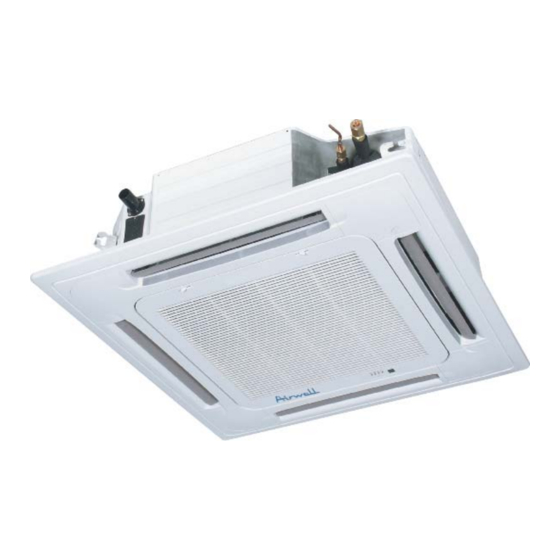
INTRODUCTION INTRODUCTION General The new KXL DCI split cassette range comprise the following RC(heat pump) models: • KXL 24 DCI • KXL 30 DCI The New DCI KN units can be easily fitted to residential and commercial applications featuring esthetic design, compact dimensions, and low noise operation. Main Features The DCI KN series benefits from the most advanced technological innovations, namely:... - Page 4 INTRODUCTION Outdoor Unit DCI outdoor units can be installed as floor or wall mounted units by using a wall supporting bracket. The metal sheets are protected by anti- corrosion paint work allowing long life resistance. All outdoor units are pre-charged. For further information please refer to the Product Data Sheet, Chapter 2.
-
Page 5: Product Data Sheet
RATING CONDITIONS PRODUCT DATA SHEET KXL 24 DCI Model Indoor Unit KXL 24 DCI Model Outdoor Unit GC 24 DCI Installation Method of Pipe Flared Characteristics Units Cooling Heating Btu/hr 24550(5110~27280) 27280(5110~30000) Capacity (4) 7.2(1.5-8.0) 8.0(1.5~8.8) Power input (4) 2.39(0.5-3.2) 2.22(0.5~3.1) EER (Cooling) or COP(Heating) (4) 3.01... - Page 6 RATING CONDITIONS KXL 30 DCI Model Indoor Unit KXL 30 DCI Model Outdoor Unit GC 30 DCI Installation Method of Pipe Flared Characteristics Units Cooling Heating Btu/hr 27280(6800~30000) 30690(5110~34100) Capacity (4) 8.0(2.0-8.8) 9.0(1.5~10.0) Power input (4) 2.65(0.5-3.2) 2.60(0.5~3.1) EER (Cooling) or COP(Heating) (4) 3.01 3.46 Energy efficiency class...
-
Page 7: Rating Conditions
INTRODUCTION RATING CONDITIONS Rating conditions in accordance with ISO 5151 and ISO 13253 (for ducted units). Cooling: Indoor: C DB 19 C WB Outdoor: 35 C DB Heating: Indoor: C DB Outdoor: 7 C DB 6 C WB Operating Limits Indoor Outdoor Upper limit... -
Page 8: Outline Dimensions
OUTLINE DIMENTIONS OUTLINE DIMENSIONS Indoor unit KXL 24 DCI: B=240mm KXL 30 DCI: B=310mm Service Manual –KXL DCI Revision 0... - Page 9 OUTLINE DIMENTIONS Outdoor Unit 4.1.1 GC 24, 30 DCI • Revision 0 Service Manual – KXL DCI...
-
Page 10: Performance Data
PERFORMANCE DATA PERFORMANCE DATA KXL 24 DCI 5.1.1 Cooling Capacity (kW)-Run Mode ID COIL ENTERING AIR DB/WB TEMPERATURE [C OD COIL ENTERING AIR DB TEMPERATURE DATA 22/15 24/17 27/19 29/21 32/23 80 - 110 % of nominal -10 - 20 80 - 105 % of nominal (protection range) 25 - 50 % of nominal... - Page 11 PERFORMANCE DATA Cooling Capacity Ratio Vs. Outdoor Temperature Outdoor Temperature [deg C] Revision 0 Service Manual - KXL DCI...
- Page 12 PRESSURE CURVES 5.1.3 Heating Capacity (kW)-Run Mode ID COIL ENTERING AIR DB TEMPERATURE [C OD COIL ENTERING AIR DB/WB TEMPERATURE DATA 3.64 3.12 2.59 -15/-16 1.55 1.66 1.77 4.81 4.28 3.76 -10/-12 1.75 1.87 1.98 5.68 5.16 4.63 -7/-8 1.91 2.02 2.13 6.12...
- Page 13 PERFORMANCE DATA Heating Capacity Ratio Vs. Outdoor Temperature Outdoor WB Temperature [deg C] 5.1.5 Capacity Correction Factor Due to Tubing Length Cooling mode 1,02 0,98 0,96 0,94 0,92 0,88 0,86 Tubing length(m) Heating mode 1. 02 0. 98 0. 96 0.
- Page 14 PRESSURE CURVES KXL 30 DCI 5.2.1 Cooling Capacity (kW)-Run Mode ID COIL ENTERING AIR DB/WB TEMPERATURE [C OD COIL ENTERING AIR DB TEMPERATURE DATA 22/15 24/17 27/19 29/21 32/23 80 - 110 % of nominal -10 - 20 80 - 105 % of nominal (protection range) 25 - 50 % of nominal 7.88...
- Page 15 PERFORMANCE DATA 5.2.3 Heating Capacity (kW)-Run Mode ID COIL ENTERING AIR DB TEMPERATURE [C OD COIL ENTERING AIR DB/WB TEMPERATURE DATA 4.10 3.51 2.92 -15/-16 1.82 1.95 2.08 5.41 4.82 4.23 -10/-12 2.06 2.19 2.32 6.39 5.80 5.21 -7/-8 2.23 2.36 2.49 6.88...
- Page 16 PRESSURE CURVES 5.2.5 Capacity Correction Factor Due to Tubing Length Cooling mode 1. 02 0. 98 0. 96 0. 94 0. 92 0. 9 0. 88 0. 86 Tubing length(m) Heating mode 1. 02 0. 98 0. 96 0. 94 0.
-
Page 17: Operating Curves
PRESSURE CURVES OPERATING CURVES Model: KXL 24 DCI 6.1.1 Cooling –Test Mode 1200 Indoor DB/WB 1100 22/15 24/17 1000 27/19 29/21 32/23 Outdoor DB Temperature 4000 Indoor 3750 DB/WB 3500 22/15 3250 24/17 3000 2750 27/19 2500 29/21 2250 32/23 2000 1750 1500... - Page 18 PRESSURE CURVES 6.1.2 Heating –Test Mode 1300 1200 1100 1000 Outdoor WB Temperature 3750 3500 Indoor 3250 3000 2750 2500 2250 2000 1750 1500 Outdoor WB Temperature 12.50 Indoor 10.50 8.50 6.50 Outdoor WB Temperature Revision 0 Service Manual - KXL DCI...
- Page 19 PRESSURE CURVES Model: KXL 30 DCI 6.2.1 Cooling –Test Mode 1200 Indoor DB/WB 1100 22/15 24/17 1000 27/19 29/21 32/23 Outdoor DB Temperature 4250 Indoor 4000 DB/WB 3750 3500 22/15 3250 24/17 3000 27/19 2750 29/21 2500 32/23 2250 2000 1750 1500 Outdoor DB Temperature...
- Page 20 PRESSURE CURVES 6.2.2 Heating –Test Mode 1200 1100 1000 Outdoor WB Temperature 4000 3750 Indoor 3500 3250 3000 2750 2500 2250 2000 1750 1500 Outdoor WB Temperature 14.00 Indoor 12.00 10.00 8.00 Outdoor WB Temperature Revision 0 Service Manual - KXL DCI...
-
Page 21: Sound Level Characteristics
SOUND LEVEL CHARACTERISTICS SOUND LEVEL CHARACTERISTICS Indoor Unit Sound Pressure Level Indoor Unit Soud Pressure Level Spectrum (Measured as Figure 4) KXL 24 DCI KXL 30 DCI Noise spectrum & NC Curves Noise spectrum & NC Curves NC65 NC65 NC60 NC60 NC55 NC55... - Page 22 SOUND LEVEL CHARACTERISTICS Outdoor units MODEL SPL dB(A) SPW dB(A) Indoor Outdoor Cooling/Heating Cooling/Heating KXL 24 DCI GC 24 DCI 55/55 65/65 KXL 30 DCI GC 30 DCI Figure 5. Microphone Distance from Unit Outdoor units Sound Pressure Level Spectrum (Measured as Figure 5) 7.4.1 GC 24,30 DCI...
-
Page 23: Electrical Data
ELECTRICAL DATA ELECTRICAL DATA Single Phase Unit Model GC 24 DCI GC 30 DCI Power Supply 1 PH ,220-240VAC ,50HZ Connected to Indoor Circuit breaker rating Starting Current○, 15 A Power Supply Wiring no хcross section 3X 2.5 mm² Interconnecting cable no хcross 4X 2.5 mm²... -
Page 24: Wiring Diagrams
REFRIGERATION DIAGRAMS WIRING DIAGRAMS Indoor Unit Outdoor Unit OUTDOOR UNIT CIRCUIT DIAGRAM OAT OCT OFAN COMP Reverse Choke coil Base valve heater U V W Outdoor unit controller PCB Jumper Flash EARTH N-COM E E V E M I f i l t er P C B EARTH Black EARTH... - Page 25 REFRIGERATION DIAGRAMS 9.2.1 GC 24,30 DCI Revision 0 Service Manual - KXL DCI...
-
Page 26: Refrigeration Diagrams
REFRIGERATION DIAGRAMS 10.1 Cooling mode 10.2 Heating mode Service Manual - KXL DCI 10-3... -
Page 27: Tubing Connections
TUBING CONNECTIONS TUBING CONNECTIONS TUBE (Inch) TORQUE (Nm) ¼” ⅜” ½” ⅝” ¾” Flare Nuts 11-13 40-45 60-65 70-75 80-85 Valve Cap 13-20 13-20 18-25 18-25 40-50 Service Port Cap 11-13 11-13 11-13 11-13 11-13 Valve Protection Cap-end Refrigerant Valve Port (use Allen wrench to open/close) Valve Protection Cap Refrigerant Valve Service Port Cap... -
Page 28: Control System
OPTIONAL ACCESSORIES CONTROL SYSTEM 12.1 General Functions and Operating Rules The DCI software is fully parametric. All the model dependent parameters are shown in Blue color and with Italic style [ parameter The parameters values are given in the last section of this control logic chapter of the service manual. - Page 29 OPTIONAL ACCESSORIES 12.1.3 Target Frequency Setting 12.1.3.1 Target Frequency Setting for DCI 50/60 The compressor target frequency is a function of the NLOAD number sent from the indoor controller and the outdoor air temperature. Basic Target Frequency Setting: NLOAD Target Frequency Maximum Frequency 10<NLOAD<127 Interpolated value between minimum and maximum...
- Page 30 12.1.5 Compressor Starting Control 12.1.5.1 Compressor starting control for DCI50/60 Step3 Step2 Step1 Time Minute Minute Min 10 Minutes 12.1.5.2 Compressor starting control for DCI 24/30 Step 1 Whenever the compressor starts up, after it has been off for more than 45 minutes, the compressor frequency cannot go below for 3 continuous minutes ( this rule comes to Step1RPS...
- Page 31 OPTIONAL ACCESSORIES 12.1.8 Outdoor Fan Control 12.1.8.1 Outdoor Fan Control for DCI72/80 OFAN operates between OFMinRPM OFMaxRPM Min time for speed change of OFAN (60 seconds). OFMinTimeReduce There are 4 defined speeds – High, Med, Low, and Very Low. The actual OFAN speeds in cool mode are defined according to the following table: Outdoor air temperature (OAT) Freq The actual OFAN speeds in heat mode are defined according to the following table...
- Page 32 12.1.9 EEV (Electronic Expansion Vavle) Control 12.1.9.1 EEV Control for DCI 24/30 The target EEV value is the sum of open loop value (OL) and a result of the accumulative correction values (CV). ∑ The EEV intial value(OL) is defined as follow: EEVBaseOpenLoop + EEVOpenLoopCpctyCrct + EEVTubeCompnst EEVBaseOpenLoop EEVOpenLoopCpctyCrct...
- Page 33 OPTIONAL ACCESSORIES When the unit is in Heat mode, the correction is defined as follow: erCTT ≥49 46, 48 43, 45 40, 42 37, 39 34, 36 31, 33 28, 30 25, 27 22, 24 12, 21 CTT- ICT 9, 11 6, 8 3, 5 0, 2...
- Page 34 12.3 Cool Mode NLOAD is calculated according to the difference between actual room temperature and user set point temperature by PI control. In high/ medium/ low indoor fan user setting, unit will operate fan in selected speed. In AutoFan user setting, fan speed will be adjusted automatically according to the calculated NLOAD.
- Page 35 OPTIONAL ACCESSORIES 12.6 Dry Mode As long as room temperature is higher then the set point, indoor fan will work in low speed and compressor will work between 0 and MaxNLOADIF1C When the room temperature is lower than the set point, compressor will be switched OFF and indoor fan will cycle 3 minutes OFF, 1 minute ON.
- Page 36 12.7.3 Compressor Overheating Protection 12.7.3.1 Compressor Overheating Protection for GC 24/30 DCI CTT Trend Fast Decreasing Increasing Fast Decreasing Change Increasing Cool Heat >105 >105 100≤ CTT < 100≤ CTT < <100 <100 98≤CTT 95≤CTT 93≤CTT < 85≤CTT < 90≤CTT ≤ 80≤CTT ≤...
- Page 37 OPTIONAL ACCESSORIES 12.7.6 Outdoor Coil Deicing Protection 12.7.6.1 Outdoor coil Deicing Protection For GC 24/30 DCI Entering Deicing Conditions Deicing operation will start when either one of the following conditions exist: Case 1: OCT < OAT – AND TLD > Case 2: OCT <...
- Page 38 12.7.7 Condensate Water Over Flow Protection Each of the pins P1, P2, P3 can have two options: 1 – When it is shorted with P4 0 – When it is not shorted to P4 Water Level Protection-1 level Level Don’t Don’t Normal care...
- Page 39 OPTIONAL ACCESSORIES 12.9 Operating the Unit from Mode Button Forced operation allows to start, stop and operate in Cooling or Heating, in pre-set temperature according to the following table: Forced operation Mode Pre-set Temperature Cooling 20 °C Heating 28 °C 12.10 On Unit Controls and Indicators 12.10.1...
- Page 40 12.10.2 Outdoor Unit controller Indicatiors Unit has three LED’s. SB LED is ON when power is ON (230 VAC, even when no communication). STATUS LED is ON when COMP is ON, and Blinks according to diagnostics mode definitions when either fault or protection occurs. FAULT LED Blinks according to diagnostics mode definitions when either fault or protection occurs.
- Page 41 OPTIONAL ACCESSORIES DNG series are defined by “family+ model”: Family +model Jumper setting New family Model definition definition J8 J7 J6 J5 J4 J3 KS+A LS+A KS+C KS+D Model selection Jumper – J7, J8 Model J9- Presence Detector/Power Shedding OPERATION Presence Detector Power Shedding Jumper –...
- Page 42 12.11.3.2 Outdoor Unit Controller For GC 24/30 DCI OFAN Jumpers OFAN use parameters Panasonic- EHD80 (ROM) Nideq OFAN (ROM) Shinano (ROM) EEPROM Compressor Jumpers Compressor use parameters TNB220 (ROM) EEPROM 12.12 Test Mode 12.12.1 Entering Test Mode System can enter Test mode in two ways: Automatically when the following conditions exists for 30 minutes continuously: Mode = Cool, Set point = 16, Room temperature = 27 (+1/−2) , Outdoor temperature = 35(+2/-1) Mode = Heat, Set point = 30, Room temperature = 20±1, Outdoor temperature = 7±(+1/-2)
- Page 43 OPTIONAL ACCESSORIES 12.13 SW Parameters 12.13.1 Indoor Units SW Parameters Model dependent parameters (KN-60) (KN-72) (KN-80) Cap .Group NomLoadC NomLoadH MaxNLOADIF1C MaxNLOADIF2C MaxNLOADIF3C MaxNLOADIF4C MaxNLOADIF5C MinRTC MaxNLOADRTC MaxNLOADIF1H MaxNLOADIF2H MaxNLOADIF3H MaxNLOADIF4H MaxNLOADIF5H MaxNLOADRTH MaxRTH MaxNLOADPSC MaxNLOADPSH 12-16 Revision 0 Service Manual - KXL DCI...
- Page 44 12.13.2 Outdoor Units SW Parameters Model dependent parameters for GC 24/30 DCI Compressor Parameters Value MinOFFTime MinOnTime MaxCTT1 MaxCTT2 MinSpeedAsCTT1 MinSpeedAsCTT2 MaxSpeedC MaxSpeedH Step1RPS Step2RPS Step3RPS (sec/RPS) NormAcc (sec/RPS) NormDec Down1(Sec/RPS) (Sec/RPS) Down2 (Sec/RPS) DeiceAcc (Sec/RPS) DeiceDec EEV Parameters Value NormEEVRate EEVCompOFFOpen EEVCompOFFTime...
-
Page 45: Troubleshooting
OPTIONAL ACCESSORIES TROUBLESHOOTING WARNING!!! When Power Up – the whole outdoor unit controller, including the wiring, is under HIGH VOLTAGE!!! Never open the Outdoor unit before turning off the Power!!! When turned off, the system is still charged (400V)!!! It takes about 3 Min. to discharge the system. Touching the controller before discharging may cause an electrical shock!!! For safe handling of the controller please refer to section 13.6 below. - Page 46 SYMPTOM PROBABLE CORRECTIVE ACTION CAUSE Indoor fan works PCB problem Replace controller when unit is OFF, and indoor fan speed is not changed by remote control command. Compressor does not Electronics Perform diagnostics (See 13.3 start control problem below), and follow the actions or protection described.
- Page 47 OPTIONAL ACCESSORIES SYMPTOM PROBABLE CORRECTIVE ACTION CAUSE Unit operates with Wrong jumper Perform diagnostics (See 13.3 wrong fan speeds or settings below), and check if units is wrong frequency operating by EEPROM parameters. 13.2 Checking the refrigeration system Checking system pressures and other thermodynamic measures should be done when system is in Test Mode (in Test mode, system operates in fixed settings).
- Page 48 13.3.1 Indoor Unit Diagnostics Problem RT-1 is disconnected RT-1 is shorted RT-2 is disconnected RT-2 is shorted Reserved Communication mismatch No Communication No Encoder Reserved Outdoor Unit Fault … Reserved Defrost protection Deicing Protection Outdoor Unit Protection Indoor Coil HP Protection Overflow Protection Reserved EEPROM Not Updated...
- Page 49 OPTIONAL ACCESSORIES 13.3.2 Indoor Unit Diagnostics and Corrective Actions Probable Cause Corrective Action Fault Check sensor Sensor failures connections or replace of all types sensor Indoor and Outdoor Replace Indoor controller Communication controllers are with mismatch different versions Communication or Check Indoor to Outdoor grounding wiring is not wiring and grounding...
- Page 50 The indoor fan Check the voltage - If there is voltage replace does not function between indoor fan capacitor or motor. correctly. terminals on the main P.C.B The outdoor fan Check the voltage - If there is no voltage does not function between indoor fan replace main P.C.B correctly.
- Page 51 OPTIONAL ACCESSORIES No cooling or - Overload safety device - Check for proper voltage, heating takes on compressor is cut out switch off power and try place, indoor and (low voltage or high again after one hour. outdoor fans temperature) working.
- Page 52 13.3.3 Outdoor Unit Diagnostics Problem OCT is disconnected OCT is shorted CTT is disconnected CTT is shorted HST is disconnected (when enabled) HST is shorted (when enabled) OAT is disconnected (when enabled) OAT is shorted (when enabled) TSUC is disconnected (when enabled) TSUC is shorted (when enabled) IPM Fault Bad EEPROM...
- Page 53 OPTIONAL ACCESSORIES 13.3.4 Outdoor Unit Diagnostics and Corrective Actions Probable Cause Corrective Action Fault Sensors failures of Check sensors all types connections or replace sensors. IPM Fault Electronics HW Check all wiring and problem jumper settings, if OK, replace electronics. Bad EEPROM No action, unless special parameters...
- Page 54 13.4 Judgment by MegaTool MegaTool is a special tool to monitor the system states. Using MegaTool requires: • A computer with RS232C port. • A connection wire for MegaTool. • A special MegaTool software. Use MegaTool according to following procedure: •...
- Page 55 OPTIONAL ACCESSORIES 13.6 Precaution, Advise and Notice Items 13.6.1 High voltage in Outdoor unit controller. Whole controller, including the wires that are connected to the Outdoor unit controller may have the potential hazard voltage when power is on. Touching the Outdoor unit controller may cause an electrical shock.
Need help?
Do you have a question about the KXL DCI Series and is the answer not in the manual?
Questions and answers