Table of Contents
Advertisement
Advertisement
Table of Contents

Related Manuals for Goodmans GCE2815PLL


Summary of Contents for Goodmans GCE2815PLL
- Page 1 INSTRUCTION MANUAL Model GCE 2815PLL In Car Radio Compact Disc Player...
-
Page 2: Table Of Contents
+12 volt antenna wire of your radio. If you are in any doubt of this connection please contact the vehicle dealer or Goodmans installation helpline. IMPORTANT: Do not forget to remove the transit screws on top of the unit, before removing the fixing cage and installing the unit. -
Page 3: Accessories
ACCESSORIES Please retain the carton and packing materials, as this is the best protection for the unit should it be necessary to return it for servicing. (1) 1 x 0.5 Amp fuse (spare fuse for + 12 volt supply wire of the unit). 1 x 15 Amp fuse (spare for memory). -
Page 4: Introduction
PLEASE READ THIS BEFORE CONNECTING THE PLAYER TO THE VEHICLE IMPORTANT NOTES Prior to final installation carry out a sound check. If high distortion or intermittent sound is experienced it is possible that the wiring to the car’s electric is poor, or that the battery needs recharging. - Page 5 REMOVING AND ATTACHING THE TRIM RING This model can be fitted to DIN E or ISO style dashboard slots. The clip on trim ring is prefitted to the front of the unit for this purpose. • It will be necessary to remove the trim ring: a.
-
Page 6: Detaching And Attaching The Front Panel
DETACHING AND ATTACHING THE FRONT PANEL The front panel of this unit can be detached in order to prevent the unit from being stolen. DETACHING THE FRONT PANEL Press the RELEASE button and detach the Front panel panel by pulling it towards you as illustrated. Warning! The front panel will become hot in use. - Page 7 FRONT PANEL PRECAUTIONS Note that if the front panel fails to lock in position properly, the control buttons may not function and the LCD display may have missing segments. Push the open button and then re-install the front panel again. 1.Do not drop the front panel.
-
Page 8: Installation
INSTALLATION/PRECAUTIONS • Choose the mounting location carefully so that the unit will not interfere with the normal driving functions of the vehicle. • Avoid installing the unit where it would be subject to high temperatures, such as from direct sunlight or hot air from the heater, or where it would be subject to dust, dirt or excessive vibration. - Page 9 WIRING IDENTIFICATION UNIT REAR VIEW OF PLAYER 1) AERIAL INPUT SOCKET FRONT RIGHT POSITIVE: WHITE 2) BATTERY: RED +12 VOLT IGNITION FRONT RIGHT NEGATIVE: WHITE – 4) MEMORY: ORANGE 10) REAR LEFT POSITIVE: BROWN PERMANENT +12 VOLT 11) REAR LEFT NEGATIVE: BROWN 5) AUTO AERIAL: ORANGE/WHITE WITH BLACK STRIPE 6) FRONT LEFT POSITIVE: GREY...
- Page 10 ISO PLUG CONNECTIONS ISO - Plug 0.5A RCA LINEOUT AERIAL SOCKET Block A: This plug is used for power supply connections only. Block B: This plug is used for connecting the loudspeakers. • If your vehicle is not fitted with an ISO type connector, use the supplied ISO plug connectors to adapt your vehicle wiring.
-
Page 11: Location Of Controls And Functions
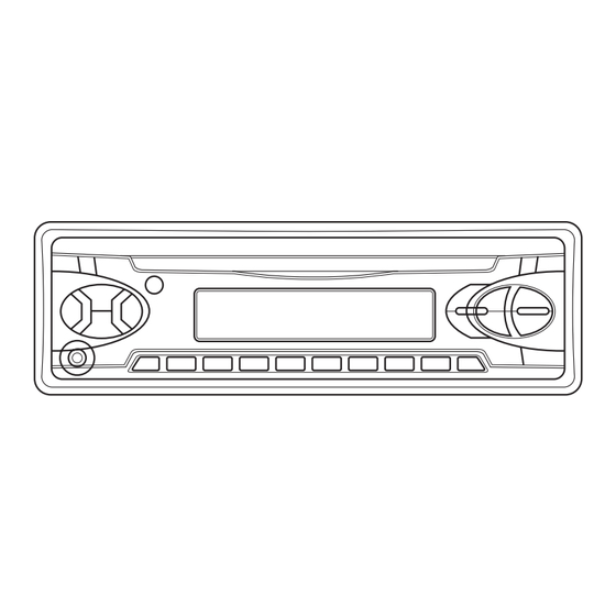
LOCATION OF CONTROLS AND FUNCTIONS 10 11 12 21 22 FUNCTION KEYS EQ Button 13. Band/Loud Button Front Panel Release Button 14. AS/PS Button Volume +/- Buttons 15. Disc Pause Button Select Button 16. Disc Scan Button CD Slot 17. Disc Repeat Button LCD Display 18. -
Page 12: Operation
OPERATION SWITCHING ON/OFF THE UNIT the same time, the tuner may Switch on the unit by pressing any button become unstable. In this (except the release button (2). To turn circumstance, 2 modes can be the unit off, press the power button (21) selected: FRONT PANEL Press the release button (2) to detach... - Page 13 OPERATION DISPLAY This allows fine tuning of the radio Press the DSP button (9) to view Clock, frequency. Briefly press the buttons Programme Type (PTY) and frequency to make small adjustments, or press of the current radio station. and hold to search quickly through the waveband.
- Page 14 OPERATION The PI codes must be identical. will be raised to a preset level. REGON will show in the display for a - TP will show in the display when the few seconds. unit is tuned to a station that is capable - Regional Mode Off: of broadcasting traffic information.
- Page 15 OPERATION - EON (Enhanced Other Networks • PLAYING ALL TRACKS IN A information) RANDOM ORDER It is a supplementary service enabling Press SHF button (19) to play all tracks the radio to obtain information not on the CD in a random order. Press only from the current station but also again to resume normal playback.
-
Page 16: Care And Maintenance
Care and Maintenance Cleaning the unit Reset Wipe with a soft cloth. If the unit is very The only time you should need to press dirty, dampen the cloth with a weak the reset buttons is: solution of neutral detergent and water, •... -
Page 17: Troubleshooting
TROUBLE SHOOTING Before going through the check list, check wiring connection. Should this fail to solve No power. 1. The car ignition is not on 1. Turn on the ignition. 2. The fuse is blown 2. Replace the fuse Disc cannot be 1. -
Page 18: Specifications
SPECIFICATION GENERAL Power Supply Requirements : DC 12 Volts, Negative Earth Chassis Dimensions : 178 (W) x 160 (D) x 50 (H) Tone Controls - Bass (at 100 Hz) : ± 10 dB - Treble (at 10 KHz) : ± 10 dB Maximum Output Power : 4 x 40 Watts CD PLAYER... - Page 19 8800-0C3011-01...
Need help?
Do you have a question about the GCE2815PLL and is the answer not in the manual?
Questions and answers