Table of Contents
Advertisement
Advertisement
Table of Contents

Related Manuals for Goodmans GCE 7103 CD


Summary of Contents for Goodmans GCE 7103 CD
- Page 1 INSTRUCTION MANUAL Model GCE 7103 CD In Car Radio Compact Disc Player 022476...
-
Page 2: Table Of Contents
+12 volt antenna wire of your radio. If you are in any doubt of this connection please the vehicle dealer or Goodmans installation helpline. IMPORTANT: Do not forget to remove the transit screws on top of the unit. -
Page 3: Accessories
ACCESSORIES Please retain the carton and packing materials, as this is the best protection for the unit should it be necessary to return it for servicing. (1) 1 x 15 Amp fuse (spare fuse for + 12 volt supply wire of the unit). 1 x 0.5 Amp fuse (spare for memory). -
Page 4: Important Notes
PLEASE READ THIS BEFORE CONNECTING THE PLAYER TO THE VEHICLE IMPORTANT NOTES Prior to final installation carry out a sound check. If high distortion or intermittent sound is experienced it is possible that the wiring to the car’s electric is poor, or that the battery needs recharging. -
Page 5: Precautions And Maintenance
Caution Vauxhall owners: Vauxhall do not follow normal ISO wiring convention which will cause Goodmans radios’ to lose the radio preset memories each time the ignition switch is turned off. To prevent such occurrences swap over the Red ignition and Orange Memory wires in the bullet connectors attached to the wiring harness of the car radio. -
Page 6: Installation/Precautions
INSTALLATION/PRECAUTIONS • Choose the mounting location carefully so that the unit will not interfere with the normal driving functions of the vehicle. • Avoid installing the unit where it would be subject to high temperatures, such as from direct sunlight or hot air from the heater, or where it would be subject to dust, dirt or excessive vibration. -
Page 7: Removing And Attaching The Trim Ring
REMOVING AND ATTACHING THE TRIM RING This model can be fitted to DIN E or ISO style dashboard slots. The clip on trim ring is prefitted to the front of the unit for this purpose. • It will be necessary to remove the trim ring: a. -
Page 8: Using The Detachable Front Panel
USING THE DETACHABLE FRONT PANEL To Detach the Front Panel 1. Press the open button (OPEN), then the front panel will be folded down. Open 2. Remove the front panel by pulling tis middle-hand outward. Front Panel 3. For safekeeping, store the front panel in the supplied protective case immediately after being removed. - Page 9 To Reinstall the Front Panel 1. Push the front panel into the main body. A ‘click’ sound should be heard. 2. Note that if the front panel fails to lock in position properly, press control button may not function and LCD display may be missing some segments. Pushing the OPEN button and then reinstall the front panel again.
-
Page 10: Wiring Identification
WIRING IDENTIFICATION UNIT REAR VIEW OF PLAYER 1) AERIAL INPUT SOCKET FRONT RIGHT POSITIVE: WHITE 2) BATTERY: RED +12 VOLT IGNITION FRONT RIGHT NEGATIVE: WHITE 3) GROUND: BLACK – WITH BLACK STRIPE 4) MEMORY: ORANGE 10) REAR LEFT POSITIVE: BROWN PERMANENT +12 VOLT 11) REAR LEFT NEGATIVE: BROWN 5) AUTO AERIAL: ORANGE/WHITE... -
Page 11: Iso Plug Connections
ISO PLUG CONNECTIONS ISO - Plug 0.5A AERIAL SOCKET Block A: This plug is used for power supply connections only. Block B: This plug is used for connecting the loudspeakers. • If your vehicle is not fitted with an ISO connector but just bare wire, then simply connect the supplied ISO plug to bare wire connector A and B to the radio’s ISO socket and connect the bare wire ends to the vehicles loudspeakers according to the wiring codes as shown below. - Page 12 Recommended Minimum Loudspeaker Power Ratings Front and Rear Loudspeakers power ratings 4 x 30 Watts RMS. Two Speaker Wiring If you intend to use only two speakers with this radio select either front or rear wiring i accordance with the power handling of the speakers fitted to you vehicle, when installing connect as per the instructions given on page 10 - 11.
-
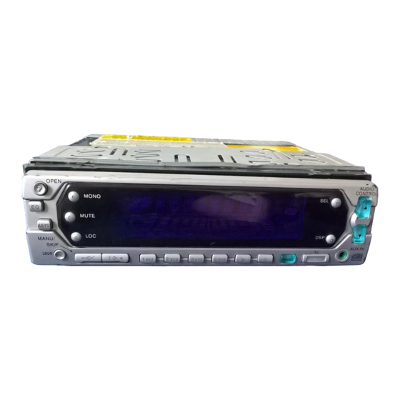
Page 13: Identification Of Controls And Functions
IDENTIFICATION OF CONTROLS AND FUNCTIONS 15 10 25 26 FUNCTION KEYS 1. Mono Button 14. Preset Buttons 2. Local Button 15. Display Button 3. Mute Button 16. Manual/Skip Up Button 4. Eject Button 17. Manual/Skip Down Button 5. Disc Slot 18. - Page 14 GENERAL OPERATION • ON/OFF/ILLUMINATE Switch on the unit by pressing any button [except OPEN button (7) and EJECT button (4)]. When system is on, press PWR/ILL button (9) shortly to control the brightness of VFD. Press it for several seconds to turn off the unit.
- Page 15 • AUXILIARY INPUT The unit can be connected to a portable audio player through the AUX IN jack (24). • FLASHING LED If the front panel is removed from the main unit, the LED (25) will be flashing. • RESET RESET button (26) is placed on the front panel and must be activated with either a ball point pen or thin metal object.
- Page 16 • AUTOMATIC MEMORY STORING & PROGRAM SCANNING - Automatic Memory Storing Press AS/PS button (18) for several seconds, the radio searches from the current frequency and checks the signal strength until one complete band search is finished. And then the 6 strongest stations are stored into the corresponding preset number button in order of reception.
- Page 17 NOTE ON CD-R/CD-RW DISCS • On this unit, in addition to an audio CD, you can play your original CD-R or CD-RW. • However, depending on the conditions of the recording equipment or the CD-R/CD-RW disc itself, some CD-Rs or CD-RWs cannot be played on this unit.
- Page 18 AERIALS AND AERIAL FITTING The normal standard telescopic aerial is designed to be used fully extended. If any segments are damaged or missing this will result in a deterioration of the radio reception. If is important to keep the aerial clean which will prevent corrosion and subsequent high resistance occurring within the segments which will lead to noisy or poor reception.
- Page 19 RADIO INTERFERENCE In the event that your player suffers from interference from your vehicles ignition or charging system, please read carefully the guidance given below. It should be noted that in the majority of cases, interference is mostly caused by a missing or defective device or the ignition HT leads are worn or are of poor quality.
- Page 20 TROUBLE SHOOTING The following indicator appears. E1, E2, E3 Press the RESET button. If this indicator still appears after pressing the RESET button, consult your nearest service dealer. BEFORE SET REMOVAL Take out the disc. If a disc remains in the CD player, the disc or set may be seriously damaged in transportation.
- Page 21 Symptom Cause Solution No sound. Adjust the volume control. Adjust the sound to the level you want. Unit is not connected properly. Double check the connections. The connection cords are not Check the speaker cords and the connected properly. other connection cords. The built-in microcomputer is Remove the compact disc, then operation...
-
Page 22: Specifications
SPECIFICATIONS GENERAL Power Supply Requirements : DC 12 Volts, Negative Ground Chassis Dimensions : 178 (W) x 165 (D) x 50 (H) Tone Controls : ± 10 dB - Bass (at 100 Hz) : ± 10 dB - Treble (at 10 KHz) Maximum Output Power : 4 x 20 Watts RMS (4 x 40 Watts Music) Current Drain...
Need help?
Do you have a question about the GCE 7103 CD and is the answer not in the manual?
Questions and answers
How to release a CD from cd player