Table of Contents
Advertisement
Quick Links
Instruction Manual
OCM Pro CF
NIVUS GmbH
Im Taele 2
75031 Eppingen, Germany
Phone +49 (0) 72 62 / 91 91 - 0
Fax +49 (0) 72 62 / 91 91 - 999
E-mail: info@nivus.de
Internet: www.nivus.com
OCM Pro CF - Rev. 07 as of 04.12.2012
Instruction Manual for
OCM Pro CF Measurement Device
(Original Instruction Manual – German)
valid as of Software Revision No. 5.08
®
Page 1
Advertisement
Table of Contents

Related Manuals for Nivus OCM PRO CF


Summary of Contents for Nivus OCM PRO CF
- Page 1 Im Taele 2 75031 Eppingen, Germany Phone +49 (0) 72 62 / 91 91 - 0 Fax +49 (0) 72 62 / 91 91 - 999 E-mail: info@nivus.de Internet: www.nivus.com OCM Pro CF - Rev. 07 as of 04.12.2012 Page 1...
- Page 2 Phone: +44 (0)1642 659294 Internet: www.nivus.de E-mail: info@nivus.com Internet: www.nivus.com NIVUS Austria Mühlbergstraße 33B NIVUS Middle East (FZE) A-3382 Loosdorf Building Q 1-1 ap. 055 Phone: +43 (2754) 567 63 21 P.O. Box: 9217 Fax: +43 (2754) 567 63 20 Sharjah Airport International E-mail: austria@nivus.com...
- Page 3 They are often protected registered trademarks even if not marked as such. OCM Pro CF - Rev. 07 as of 04.12.2012 Page 3...
-
Page 4: Table Of Contents
OCM Pro Power Supply Wall and Panel Mount Enclosure ..44 Regulator Mode ................45 6.5.1 General ..................45 6.5.2 Construction of Measurement Section ........46 6.5.3 Regulator Mode Wiring Diagram ..........47 6.5.4 Control Algorithm ................. 47 Page 4 OCM Pro CF - Rev. 07 as of 04.12.2012... - Page 5 Verification of Combi Sensor with Pressure Measurement Cell157 11.3 Verification of external Level Measurement ......158 11.4 Verification and Simulation of Input and Output Signals ... 159 11.5 Verification of Flow Velocity Measurement ....... 159 OCM Pro CF - Rev. 07 as of 04.12.2012 Page 5...
- Page 6 Sensors ..................160 Table "Manning - Strickler Coefficients" ....... 161 Emergency ............... 162 Dismantling/Disposal ............162 Table of Pictures .............. 162 Index ................. 166 EC Declaration of Conformity (Appendix) ..... 168 Page 6 OCM Pro CF - Rev. 07 as of 04.12.2012...
-
Page 7: Ex-Approval Of Transmitter
OCM Pro CF Ex-Approval of Transmitter The approval is only valid in connection with the respective indication on the transmitter nameplate. The complete Ex approval (4. Supplement) is available on http://www.nivus.com. OCM Pro CF - Rev. 07 as of 04.12.2012 Page 7... -
Page 8: Overview And Use In Accordance With The Requirements
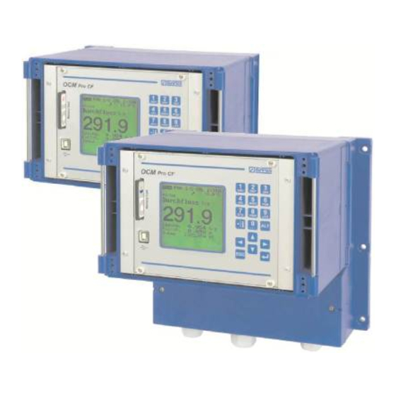
2 USB interface (for service purposes only) 3 Keypad 4 Graphic display 5 Cable glands (only wall mount enclosure) 6 Terminal clamp housing with cover (only wall mount enclosure) Fig. 2-1 Overview enclosure Page 8 OCM Pro CF - Rev. 07 as of 04.12.2012... - Page 9 6 Flow velocity wedge sensor, type CSM 7 Air-ultrasonic level sensor, type DSM 8 Electronic Box for connection of sensors types CSM and DSM Fig. 2-2 Overview sensors and electronic box OCM Pro CF - Rev. 07 as of 04.12.2012 Page 9...
-
Page 10: Use In Accordance With The Requirements
In case of using sensors from third party manufacturers the operator must carry out a system review according to EN 60079-25! The required specifications of the OCM Pro CF Ex version can be taken from the EC-type examination certificate TÜV 00 ATEX 1572. -
Page 11: Specifications
Evaluation software Type: NivuSoft for Windows XP, Windows Vista or Windows 7 for readout and evaluation of data, creation of hydrographs, average values, hour / day and month totals etc. OCM Pro CF - Rev. 07 as of 04.12.2012 Page 11... -
Page 12: General Notes On Safety And Danger
All operations, which go beyond steps to install, to connect or to program the device, must be carried out by NIVUS staff only due to reasons of safety and guarantee. 3.1.2 Special Danger Notes Please note that due to the operation in the waste water field, transmitter, sensors and cables may be loaded with dangerous disease germs. -
Page 13: Device Identification
This ensures correct and quick processing. OCM Pro CF in panel mount enclosure with S4/M4 backplane: OCM Pro CF in wall mount enclosure with S3/M3 backplane: OCM Pro CF in wall mount enclosure with S4/M4 backplane: Ex type plate: Fig. -
Page 14: Installation Of Spare Parts And Parts Subject To Wear And Tear
In Germany the Industrial Safety Ordinance must be observed. Page 14 OCM Pro CF - Rev. 07 as of 04.12.2012... -
Page 15: Functional Principle
(dirt particles, gas bubbles or similar). The OCM Pro CF type S4 either uses a POA or a CS2 sensor which simultane- ously determine flow velocity and flow level. Alternatively, a CSM sensor in con- junction with the electronic box EBM may be connected, which however merely is a flow velocity sensor. - Page 16 ® Instruction Manual OCM Pro CF Fig. 4-1 Possible combinations OCP type S4 Fig. 4-2 Possible combinations OCP type M4 Page 16 OCM Pro CF - Rev. 07 as of 04.12.2012...
- Page 17 9 Duct for pressure measurement (optional) 10 Protective cover for sensor cable and protective hose fastening 11 Sensor cable 12 Protective hose (optional) Fig. 4-4 Combi sensor type CS2 with pressure measurement cell OCM Pro CF - Rev. 07 as of 04.12.2012 Page 17...
-
Page 18: Level Measurement Using Water Ultrasound
The fixed level, which is determined by the sensor crystal position, is added to the determined value h . This results in the total level h. Page 18 OCM Pro CF - Rev. 07 as of 04.12.2012... -
Page 19: Level Measurement Using Pressure
OCM Pro CF - Rev. 07 as of 04.12.2012 Page 19... - Page 20 OCM Pro display and can be read there for inspection and control purposes. Fig. 4-9 Investigated flow profile Page 20 OCM Pro CF - Rev. 07 as of 04.12.2012...
- Page 21 This vol- ume can either be a free programmable analog signal or an impulse signal as well. OCM Pro CF - Rev. 07 as of 04.12.2012 Page 21...
-
Page 22: Device Versions
OCM Pro CF Device Versions The OCM Pro CF measurement transmitter is available in different versions. The type key below gives a brief overview on the various possibilities. The transmitters vary in terms of the number of inputs and outputs, enclosure construction, data transmission options, power supply and Ex protection. -
Page 23: Storing, Delivery And Transport
Please check your delivery according to the delivery note for completeness and intactness immediately after receipt. Any damage in transit must be instantly re- ported to the carrier. An immediate, written report must be sent to NIVUS GmbH Eppingen as well. -
Page 24: Installation
For electric installation the local regulations in the respective countries (e.g. VDE 0100 in Germany) must be referred to. The OCM Pro CF power supply must be separately protected by a 6 A slow- blow fuse and has to be isolated from other facility parts (separate turn-off, e.g. -
Page 25: Wall Mount Enclosure Installation And Connection
This problem may be solved by using methylated spirit or car polish if required to clean the clear view door or the display. If these measures should not be suc- cessful, clear view door as well as display can be replaced by NIVUS (subject to costs). -
Page 26: Wall Mount Enclosure Dimensions
Transmitter type S4: 2 glands M20 x 1.5 1 gland M16 x 1.5 2 dummy plugs M20 x 1.5 2 dummy plugs M16 x 1.5 Page 26 OCM Pro CF - Rev. 07 as of 04.12.2012... - Page 27 The sensors (flow velocity, combi, air-ultrasonic or 2-wire level sensors) are equipped with connection plugs due to better handling of the wall mount enclo- sure. The pre-configured cable tips of the NIVUS sensors or single and multi- wired cables with cross-sectional areas of 0.18-2.5 mm² (0.007-0.098 in) can be connected to these plugs.
- Page 28 DI1, DI2, DC-, AI1, AI2, AI3, AI4, AO1, AO2, AO3, AO4 Internal wiring: b2 + b15; b3 + a14 Fig. 6-2 Wiring diagram OCM Pro CF wall mount enclosure Page 28 OCM Pro CF - Rev. 07 as of 04.12.2012...
-
Page 29: Wall Mount Enclosure Sensor Connection
OCM Pro type S4W0 / M4W0 Fig. 6-4 Connecting a second velocity sensor to the OCM Pro type M4W0 Fig. 6-5 Connecting a third velocity sensor to the OCM Pro type M4W0 OCM Pro CF - Rev. 07 as of 04.12.2012 Page 29... - Page 30 Connection 2. electronic box Type EBM with water-ultrasonic sensor Type CSM to Type M4W0 Fig. 6-8 Connection 3. electronic box Type EBM with water-ultrasonic sensor Type CSM to Type M4W0 Page 30 OCM Pro CF - Rev. 07 as of 04.12.2012...
- Page 31 If the level measurement is carried out by a 2-wire probe (NivuBar, NivuCompact 2-wire echo sounder or similar) which is supplied by the OCM Pro, please follow the wiring diagram below: Fig. 6-11 Connecting a 2-wire sensor (EX for level measurement OCM Pro CF - Rev. 07 as of 04.12.2012 Page 31...
- Page 32 If the mA signal for level measurement is provided from an external transmitter (such as NivuMaster) connect to clamps as follows: Fig. 6-13 Connecting external level measurement from NivuMaster to type W0 Page 32 OCM Pro CF - Rev. 07 as of 04.12.2012...
-
Page 33: Wall Mount Enclosure Overvoltage Protection
SonicPro 3x1 24 V/24 V. If using the sensors in Ex areas consider the connected loads of the overvolt- age protection devices as well as capacity and inductance of the NIVUS sen- sor cables (POA, CS2, OCL, EBM) additionally! The maximum permissible NIVUS cable lengths in Ex areas are: - single-side overvoltage protection: 135 m (443 ft.) - Page 34 ® Instruction Manual OCM Pro CF Fig. 6-14 Wall mount enclosure - connecting the overvoltage protection for power supply and analog inputs and outputs Page 34 OCM Pro CF - Rev. 07 as of 04.12.2012...
- Page 35 ® Instruction Manual OCM Pro CF Fig. 6-15 Overvoltage protection water-ultrasonic sensor or electronic box, wall mount enclosure Fig. 6-16 Overvoltage protection air-ultrasonic sensor, type OCL, wall mount enclosure OCM Pro CF - Rev. 07 as of 04.12.2012 Page 35...
-
Page 36: Mounting And Connection Of The Panel Mount Enclosure
3.0 mm or 3.5 mm blade. Before the first connection use a screw driver to exert slight pressure on the screw of the clamping connection to ensure proper opening and a correct connection. Page 36 OCM Pro CF - Rev. 07 as of 04.12.2012... - Page 37 Ex-area input external level measurement connection v-sensor 3 connection ultrasonic level connection v-sensor 2 v-sensor 1 sensor (air us) Fig. 6-18 Wiring diagram OCM Pro CF panel mount enclosure OCM Pro CF - Rev. 07 as of 04.12.2012 Page 37...
-
Page 38: Panel Mount Enclosure Sensor Connection
OCM Pro CF, type S4F0 / M4F0 Fig. 6-20 Connecting a second flow velocity sensor to type M4F0 Fig. 6-21 Connecting a third flow velocity sensor to type M4F0 Page 38 OCM Pro CF - Rev. 07 as of 04.12.2012... - Page 39 Connection 2. electronic box Type EBM with water-ultrasonic sensor Type CSM to Type M4F0 Fig. 6-24 Connection 3. electronic box Type EBM with water-ultrasonic sensor Type CSM to Typ M4F0 OCM Pro CF - Rev. 07 as of 04.12.2012 Page 39...
- Page 40 Connecting a 2-wire sensor EX for level measurement to type If using the sensors in Ex-areas, the sensor cables must not be directed past the mechanical shield between the termination blocks. Page 40 OCM Pro CF - Rev. 07 as of 04.12.2012...
- Page 41 If the mA signal for level measurement is provided from an external transmitter (such as NivuMaster), connect to clamps as follows: Fig. 6-29 Connecting external level measurement from NivuMaster to type F0 OCM Pro CF - Rev. 07 as of 04.12.2012 Page 41...
-
Page 42: Panel Mount Enclosure Overvoltage Protection
OCM Pro CF 6.3.6 Panel Mount Enclosure Overvoltage Protection Fig. 6-30 Panel mount enclosure - connecting the overvoltage protec- tion for power supply and analog inputs and outputs (panel mount enclosure) Page 42 OCM Pro CF - Rev. 07 as of 04.12.2012... - Page 43 ® Instruction Manual OCM Pro CF Fig. 6-31 Overvoltage protection water-ultrasonic sensor or electronic box, panel mount enclosure Fig. 6-32 Overvoltage protection air-ultrasonic sensor type OCL, panel mount enclosure OCM Pro CF - Rev. 07 as of 04.12.2012 Page 43...
-
Page 44: Ocm Pro Power Supply Wall And Panel Mount Enclosure
Please note, when using this supply voltage (e.g. for digital inputs with control signals), it must not be shielded through the complete switchgear in order to maintain disturbing interferences on a low level. Fig. 6-34 AC model power supply Page 44 OCM Pro CF - Rev. 07 as of 04.12.2012... -
Page 45: Regulator Mode
If you operate an OCM Pro CF, type S4 for flow rate control please use a sufficient external controller and program it according to manufacturer specifications. -
Page 46: Construction Of Measurement Section
Chap.6.5.3) The assignment of the digital outputs to the regulator cannot be modified. The input current on the digital inputs of the OCM Pro CF is 10 mA. Please ensure contact reliability by selecting sufficient contact materials on the end switch of the control slide valve. -
Page 47: Regulator Mode Wiring Diagram
The input current per digital input is 10 mA. In case of driving the slide valves via the digital inputs always use all the 3 messages. Activating one message only may result in disturbed regulator operation. OCM Pro CF - Rev. 07 as of 04.12.2012 Page 47... -
Page 48: Communication
Do not confuse OCM Pro CF remote access and process conducting systems. The OCM Pro CF requires direct dialog with the user via PC. There is no real- time access. It is not possible to carry out automatic data transmission Page 48 OCM Pro CF - Rev. - Page 49 NIVUS. The system administrator is responsible for the amount of future communica- tion expenses arising. OCM Pro CF - Rev. 07 as of 04.12.2012 Page 49...
-
Page 50: Communication Options
This setup is depicted in Fig. 6-39. Internet connection via access portal (see Fig. 6-40) It is required to use an OCM Pro CF equipped with according hardware such as analog modem, ISDN modem or GPRS to set up such a connection. -
Page 51: Communication Setup Via Access Portal
1. Select your unit on >www.nivus.com< using the access portal. 2. The portal will “wake up” the unit sending a direct call. 3. The OCM Pro CF is setting up Internet access logging in to the portal subsequently. 4. The portal is going to establish a connection between unit and user using the internal OCM Pro CF web server. - Page 52 Measurement place selection After selecting the desired measurement place and clicking the "Connect" button communication with the selected OCM Pro CF will be established. User name and password are going to be verified again and the homepage contained in the OCM Pro CF will be transmitted.
-
Page 53: Data Transmission
PC! © The Java Applet is a third party software and NIVUS therefore cannot accept any liability of the use of it. Download and installation of programs or software may damage your comput- er and is therefore completely left at user’s risk! OCM Pro CF - Rev. - Page 54 Java -Applet starting After starting Java successfully, the OCM Pro CF display now is indicated in the same manner as if being on-site. The OCM Pro can now be operated by using the PC keyboard (arrow keys >left<, >right<, >up<, >down< and >Enter<, >ESC< and >ALT<) exactly the same way as if using the keys on the unit front board.
- Page 55 2 ZIP-file area 3 Delete area (to be moved into backup folder) Fig. 6-47 Selecting the file to transmit or to delete Fig. 6-48 Saving transmitted files on PC OCM Pro CF - Rev. 07 as of 04.12.2012 Page 55...
- Page 56 Fig. 6-49 Created backup folder Files which have been moved into the backup folder will be deleted irrevocably from the OCM Pro CF memory card if clicked again for deleting. Fig. 6-50 Contents of created backup folder Fig. 6-51...
- Page 57 A click on the >Trend< button on the left-hand side enables to indicate a trend graph parallel to the trend screen indicated on the OCM Pro CF to visualise data stored in the internal unit memory. The range of data to be indicated covers a maximum of 90 days.
- Page 58 This will take you back to the NIVUS homepage. If no data transmission has been executed for 5 minutes, the OCM Pro CF will automatically interrupt the connection in order to avoid unnecessary expens- Page 58 OCM Pro CF - Rev.
-
Page 59: Initial Start-Up
To ensure a correct function of the OCM Pro CF this instruction manual must be read thoroughly! The OCM Pro CF must be wired in accordance with the wiring diagram, see chapter 6.2.4... -
Page 60: Operator Panel
1 Decimal place / Info key 2 Numeric and alphabetic keys 3 Shift key 4 0 / - navigation key 5 Control key 6 Confirmation key (ENTER) 7 Escape key Fig. 7-1 Operator panel Page 60 OCM Pro CF - Rev. 07 as of 04.12.2012... -
Page 61: Display
Instruction Manual OCM Pro CF Display OCM Pro CF has a large back-lit graphic display with a resolution of 128 x 128 pixel. This ensures to comfortably read current values. 1 Indicates activated data storage 2 Indicates activated service mode... - Page 62 This menu is the most extensive of the OCM Pro CF. It is for the complete parameter setting of dimensions of the measurement place, sensor selection, analog and digital inputs and outputs, stor- age, data transmission and regulator function.
-
Page 63: Operation Basics
The key “dot/i“ serves for entering digits. In RUN-Mode it also re- calls internal information on device, software version, MAC ad- dress, serial no. of transmitter and connected NIVUS sensors. Fur- thermore it restarts communication between transmitter, flow veloc- ity sensor and air-ultrasonic sensor. -
Page 64: Parameter Setting
Modifications concerning language, units, contrast and display brightness do not require the PIN code as these settings influence just the way of representation and not measurement or the output of measurement values. Page 64 OCM Pro CF - Rev. 07 as of 04.12.2012... - Page 65 OCM Pro CF This instruction manual describes all programming options of the OCM Pro CF. Depending on the device type various inputs and outputs as well as communication and data transmission features may not be available. They may be programmable, but may not be available to be used as outputs or to be connected (see also Chapter 2.3).
- Page 66 Fig. 8-4 Additional sensor information If older sensors are in use it may not possible to indicate the sensor information completely. This procedure is required after each sensor change. Page 66 OCM Pro CF - Rev. 07 as of 04.12.2012...
-
Page 67: Operation Mode (Run)
Instruction Manual OCM Pro CF During the final inspection a system reset is performed and the OCM Pro CF is shipped subsequently. The unit hence is reset to factory defaults. Inde- pendent from this, we recommend to execute one more system reset (PAR/Settings/System reset) prior to programming parameters in order to ensure a defined basic state. - Page 68 (comparable with rout mileage counters in cars). This value can be reset to >0< at any time by pressing the >ALT<-key. This reset does not influence the total- izer. Page 68 OCM Pro CF - Rev. 07 as of 04.12.2012...
- Page 69 (level) will be recorded for the past days. Values can be indi- vidually selected and viewed in a submenu. Fig. 8-11 Trend value selection (varying screens) OCM Pro CF - Rev. 07 as of 04.12.2012 Page 69...
-
Page 70: Display Menu (Extra)
Display Menu (EXTRA) This menu allows to modify settings such as basic screen, units, language as well as the display itself. The following submenus are available: Fig. 8-13 Extra submenus Page 70 OCM Pro CF - Rev. 07 as of 04.12.2012... - Page 71 The clock settings can be modified if required (different time zones, summer time / winter time etc.). First select the menu point >Info<: Fig. 8-16 System time submenu OCM Pro CF - Rev. 07 as of 04.12.2012 Page 71...
- Page 72 After the new value has been set confirm twice using the "Enter“ key and type in the PIN “2718“ (up to 2 faulty entries possible). Otherwise the new value will not be accepted. Fig. 8-18 Totalizer modification Fig. 8-19 PIN request Page 72 OCM Pro CF - Rev. 07 as of 04.12.2012...
-
Page 73: Parameter Menu (Par)
Instruction Manual OCM Pro CF Parameter Menu (PAR) This menu is the most extensive and most important regarding the OCM Pro CF settings. It nevertheless is sufficient in most cases to set only some essential pa- rameters, which usually are:... - Page 74 This is a special parameter which enables to easily set parameters for large special profiles with convex tops. This parameter will not be required for the very most applications! Mainly, authorised NIVUS personnel is going to use this function; which nevertheless will be described here briefly.
- Page 75 Q= f(h) Fig.8-23 Channel shape selection Select channel shape with "Up“ and "Down“ keys. Confirm selection with “Enter“. The selected profile will be indicated in the programming mode screen. OCM Pro CF - Rev. 07 as of 04.12.2012 Page 75...
- Page 76 Confirm with “Enter“. A request will come up subsequently asking for known relations. Fig.8-25 Custom shape menu Channel Dimensions Type in the respective channel dimensions depending on the profile chosen before. Page 76 OCM Pro CF - Rev. 07 as of 04.12.2012...
- Page 77 In order to define the zero point of the channel start by entering 0 – 0 in break- point 1. All further breakpoints can be set freely regarding height as well as width/area. OCM Pro CF - Rev. 07 as of 04.12.2012 Page 77...
- Page 78 Pipe Programming subdivided profiles requires comprehensive knowledge and experience in operating the OCM Pro. To avoid faulty programming or if in doubt this procedure should be performed by NIVUS service personnel or expert companies authorised by NIVUS. Page 78 OCM Pro CF - Rev. 07 as of 04.12.2012...
-
Page 79: Parameter Menu "Level
Fig. 8-29 Selection low-flow volumes The suppression of low-flow volumes is no offset but a limit value! 8.4.2 Parameter Menu “Level “ Fig. 8-30 Menu level measurement OCM Pro CF - Rev. 07 as of 04.12.2012 Page 79... - Page 80 4 Fixed value for permanently full filled applications or for testing purposes 5 Pressure measurement cell integrated into flow velocity sensor, types: POA-V1D0 or CS2-V2D0 6 2-wire probe, e.g. types NM5-3101 or HSB0HG Fig. 8-32 Determination of sensor type Page 80 OCM Pro CF - Rev. 07 as of 04.12.2012...
- Page 81 (e.g. sedimentation or risk of soiling)! This may result in echo loss and meas- urement failure. In this case use a different level sensor (ultrasound from top down or pressure measurement cell). OCM Pro CF - Rev. 07 as of 04.12.2012 Page 81...
- Page 82 This selection is for level measurement by using external 2-wire Ex probes sup- plied by OCM Pro CF such as a pressure probe type NivuBar Plus or a type NivuCompact echo sounder. Can be combined with the flow velocity sensor.
- Page 83 Here the level is measured by using an external 2-wire such as the type NivuMaster echo sounder or a pressure probe type HydroBar. Both can be com- bined with the flow velocity sensor. OCM Pro CF - Rev. 07 as of 04.12.2012 Page 83...
- Page 84 The pressure sensor may be installed out of the centre if the risk of sedimentation or soiling should occur (Fig. 8-39). 1 Sedimentation, soiling Fig. 8-39 Combination: Air-ultrasound and internal pressure Page 84 OCM Pro CF - Rev. 07 as of 04.12.2012...
- Page 85 To be used in applications as described in water-US int. + air-US. An external 2-wire sensor instead of an air-ultrasonic sensor is going to be used to detect low flow levels (expediently an echo sounder). OCM Pro CF - Rev. 07 as of 04.12.2012 Page 85...
- Page 86 When selecting the water-ultrasonic sensor (h), this value is set to 10 mm by default. The value is equal to the surface above the channel bottom of the integrated level sensor of type POA. Page 86 OCM Pro CF - Rev. 07 as of 04.12.2012...
- Page 87 NIVUS, pressure and water-US 1 height h: mounting height sensor type pressure internal Fig. 8-45 Mounting height of level sensors in case of selection pressure internal or water-US internal OCM Pro CF - Rev. 07 as of 04.12.2012 Page 87...
- Page 88 Select layers This parameter will be indicated only if a sensor combination has been selected. The OCM Pro CF automatically aligns the sensors to partial layers. Layer borders however may be defined freely as well. Use the >ALT<-key to do this.
- Page 89 2-wire probe. Span: the measurement span (equal to 20 mA from the OCM Pro CF analog input) shall be adjusted to the span of the analog output of the 2-wire probe used.
- Page 90 It is possible to select the universal sensor within the program structure, but a certain measurement may not be possible however if an insufficient sensor has been chosen. Page 90 OCM Pro CF - Rev. 07 as of 04.12.2012...
-
Page 91: Parameter Menu „Velocity
Flow velocity measurement using a sensor fastened on a float. In this case the measurment is executed from the top down. V_sensor Pos-alpha: Flow velocity measurement using a wedge or pipe / tube sensor installed in an angle varying from the perpendicular. OCM Pro CF - Rev. 07 as of 04.12.2012 Page 91... - Page 92 "Float" has been selected. If sensor type "float" has been selected, enter the distance from the water sur- face to horizontal area at the tip of the pipe sensor here. Page 92 OCM Pro CF - Rev. 07 as of 04.12.2012...
- Page 93 The path length (w) will be determined automatically as soon as the distance to the water surface is shorter due to the filling level. Fig. 8-56 Mounting place at „Pos-alpha“ OCM Pro CF - Rev. 07 as of 04.12.2012 Page 93...
- Page 94 Connecting 2 or 3 flow velocity sensors: Programming additional sensors requires extensive hydraulic knowledge and has to be carried out exclusively by NIVUS staff or an expert company author- ised by NIVUS in order to avoid faulty programming! This is why profile parameter setting with several sensors is not mentioned comprehensively.
- Page 95 1 within the sequence and hence has to be installed on the lowest point of the application. Fig. 8-61 Sensor Assignment if using multiple v-sensors OCM Pro CF - Rev. 07 as of 04.12.2012 Page 95...
-
Page 96: Parameter Menu "Analog Inputs
Various numbers of analog inputs are available depending on the type of trans- mitter, such as in case of transmitter type >S4<: 1 analog input (galvanically isolated) for 2-wire sensors 1 additional analog input for external level sensor connection Page 96 OCM Pro CF - Rev. 07 as of 04.12.2012... - Page 97 Select between measurement spans of 0-20 mA and 4-20 mA here. Optional use of 0-5 V or 0-10 V voltage inputs requires the unit hardware to be modified respectively which can be carried out by NIVUS service personnel only. Units This Parameter is going to be assigned to the breakpoint table below using the saved name.
- Page 98 4 mA and 20 mA. Offset In addition to the input current, a fixed positive or negative offset using the unit chosen before can be added to the analog value. Page 98 OCM Pro CF - Rev. 07 as of 04.12.2012...
-
Page 99: Parameter Menu „Digital Inputs
Digital inputs – submenu This section enables to set and to assign the digital input signals „Control OPEN“, „Control CLOSED“ and „Torque CLOSED“. The OCM Pro CF, type >M4< requires these inputs for regulator operation. The function >Lock v-measurement< is exclusively available for digital input 1 Fig. -
Page 100: Parameter Menu "Analog Outputs
Basically 4 analog outputs can be chosen and set although transmitters type "S4" are equipped with 2 analog outputs only. Channel number Select from analog outputs 1–4 which one is to be set by using the following parameters. Page 100 OCM Pro CF - Rev. 07 as of 04.12.2012... - Page 101 Due to its hardware configuration only type >M4< allows to route the analog input to the analog output! Type >S4< can be programmed accordingly but wiring however cannot be implemented! OCM Pro CF - Rev. 07 as of 04.12.2012 Page 101...
- Page 102 Pressing this key will select between the following functions: 0 mA hold (will hold the latest valid signal value until the error has been removed or the error is no longer existent) 4 mA or 20,5 mA Page 102 OCM Pro CF - Rev. 07 as of 04.12.2012...
-
Page 103: Parameter Menu "Digital Outputs
(relay will energise if a velocity limit value [to be set] has been exceeded and will de-energise if velocity falls below a second limit val- ue [to be set].) OCM Pro CF - Rev. 07 as of 04.12.2012 Page 103... - Page 104 (ON>OFF) or as in-bounds alarm (ON<OFF). Pulse parameter This menu will be indicated only if the function >Impulses< has been chosen. Page 104 OCM Pro CF - Rev. 07 as of 04.12.2012...
-
Page 105: Parameter Menu „Control Unit
The additional submenus are not indicated before the function has been ena- bled by pressing the >ALT< key. No regulator setting options will be shown if the regulator has not been enabled. Fig. 8-76 Enabling the control unit OCM Pro CF - Rev. 07 as of 04.12.2012 Page 105... - Page 106 ® Instruction Manual OCM Pro CF Set point Type: choose between internal (setpoint defined in OCM Pro CF) and external setpoint (setpoint externally preset via dedicated analog input 4. Fig. 8-77 Setting the set point type Analog input 4 is the dedicated hardware input for analog setpoint signals.
- Page 107 0/4-20 mA. 0-5/10 V can be set by NIVUS service personnel only. set point input linearisation (normally >2< is going to be entered as number of breakpoints. Set the setpoint start (=0) to 0/4-20 mA and the setpoint stop to 20 mA subsequently.
- Page 108 D w from setpoint w. The higher the propor- tionality factor, the longer the regulating time of the slide valve at the same con- trol deviation. Fig. 8-81 Assignment of P-Factor Page 108 OCM Pro CF - Rev. 07 as of 04.12.2012...
- Page 109 Hence the minimum control impulse duration should be speci- fied longer than motor start-up time + gear clearance + slide valve clearance. OCM Pro CF - Rev. 07 as of 04.12.2012 Page 109...
- Page 110 During permanent op- eration this is going to be executed without any run time interruption. Fig. 8-86 Enabling quick close function Page 110 OCM Pro CF - Rev. 07 as of 04.12.2012...
- Page 111 The number of flush events can be set from 1 to 9. Fig. 8-88 Enabling the flush function The flush function is not available during active control operation. Fig. 8-89 Flush function parameters OCM Pro CF - Rev. 07 as of 04.12.2012 Page 111...
- Page 112 = defines how many times the flush event is to be executed. A complete flush event consists of impounding duration + duration of flush. Fig. 8-92 Setting the number of cycles (flush events) Page 112 OCM Pro CF - Rev. 07 as of 04.12.2012...
- Page 113 Setting water level duration 1 Backwater 2 Impounding duration 3 Number of flush events 4 Start day, start time 5 Duration of flush Fig. 8-95 Graphic representation of the flush function OCM Pro CF - Rev. 07 as of 04.12.2012 Page 113...
-
Page 114: Parameter Menu "Settings
Selecting “YES“ is going to reset the system to the basic parameter settings. The default settings will be restored and all customer modifications will be set to default condition (system general reset)) Page 114 OCM Pro CF - Rev. 07 as of 04.12.2012... -
Page 115: Parameter Menu "Storage Mode
Compact Flash Card. It is possible to use NIVUS Compact Flash cards with capacities from 8 to 128 MB. These cards can be purchased from your local NIVUS representative. - Page 116 PC and therefore does not accept the cards formatted on PC. Data will be saved as mean values averaged over the memory interval set, not as current values at the moment of saving. Page 116 OCM Pro CF - Rev. 07 as of 04.12.2012...
- Page 117 This parameter point is to define which data sets are to be stored in addition to the automatic storage of filling level, average flow velocity, volume and medium temperature. Choose from analog input 1-4 and system condition here. Fig. 8-104 Selectable data OCM Pro CF - Rev. 07 as of 04.12.2012 Page 117...
- Page 118 There are various units available depending on the selection made previously. (see chap. 8.3). Fig. 8-105 Selecting the unit system in storage mode Fig. 8-106 Selecting the measurement value in storage mode Page 118 OCM Pro CF - Rev. 07 as of 04.12.2012...
-
Page 119: Data Structure On Memory Card
Data structure on memory card DATA Day totals are saved in the data file >TOTAL.TXT< in this folder. Save by using the menu points >I/O/Memory card/Day values< (see chapter 8.5.8) OCM Pro CF - Rev. 07 as of 04.12.2012 Page 119... - Page 120 If the name of the measurement place saved on card does not comply with the name of the measurement place saved in the OCM Pro CF, the unit will prompt to format the card. The OCM Pro CF will not save any data as long as the card has not been formatted.
-
Page 121: Parameter Menu "Communication
Intranet, analog modem, ISDN modem or GPRS modem is available. Direct data exchange via Ethernet / Modbus TCP is possible as well. If no other NIVUS device has been connected to Internet at the moment of initial start-up, it is indispensable to have the portal initialised by the NIVUS service. - Page 122 The default setting (255.255.000.000) is normally suitable for most connections. Fig. 8-113 Setting the IP address manually If in doubt please consult your responsible system administrator or use the NIVUS initial start-up service. Page 122 OCM Pro CF - Rev. 07 as of 04.12.2012...
- Page 123 The provider will refuse service in case of faulty entry. Password: to be assigned by the user and hence depends on user name. The provider will refuse service in case of faulty entry. OCM Pro CF - Rev. 07 as of 04.12.2012 Page 123...
- Page 124 The connection will be interrupted briefly every night at 02:00 AM. The modem then is reconnecting automatically with the pro- vider and is provided with a new IP address. Page 124 OCM Pro CF - Rev. 07 as of 04.12.2012...
- Page 125 Data format: Select between text file and binary file. Binary files are for inte- gration of the unit into the "NICOS" process conducting system by NIVUS. Cycle: This defines the cycle to send the data mails (e.g. every 24 hours) Delay: The delay entered here refers to the transmission cycle set.
- Page 126 OCM Pro CF Direct access Required only if a direct 1:1 connection to the OCM Pro CF is desired to be set up via Laptop/PC, network cable and the internal RJ45 interface. In this case determine both; password as well as user name for this internal connection on PC/Laptop.
-
Page 127: Signal Input/Output Menu (I/O)
The function is mostly being used to control current signals from external level / height measurement units during initial start-up. Normally >Values in [mA/V]< will be set. A screen similar to the one below will come up: Fig. 8-124 Analog value indication OCM Pro CF - Rev. 07 as of 04.12.2012 Page 127... -
Page 128: I/O Menu "Digital Inputs
The actual current on the output clamps will not be displayed. The only signal visible is the one the analog output converter is receiving for output purposes. External faulty wiring neither can be detected nor indicated in this menu. Page 128 OCM Pro CF - Rev. 07 as of 04.12.2012... -
Page 129: I/O Menu „Digital Outputs
Fig. 8-129 Basic selection menu V-sensor Choosing this point is going to bring up a 2-page table including all individual velocities measured and the heights of the respective measurement windows. OCM Pro CF - Rev. 07 as of 04.12.2012 Page 129... - Page 130 8.4.2) different menus are displayed: Example 1: 1 Level 2 Level water-ultrasound 3 Level pressure internal 4 Level air-ultrasound NIVUS Fig. 8-131 Menu selection with water-ultrasonic, pressure and air-ultrasonic Page 130 OCM Pro CF - Rev. 07 as of 04.12.2012...
- Page 131 (double and multiple reflections caused by the echo signal moving back and forth between the interfaces water/air and water/ground) are lower and wider. OCM Pro CF - Rev. 07 as of 04.12.2012 Page 131...
-
Page 132: I/O Menu "Interfaces
This menu is visible only if the controller has been enabled in the PAR menu. Having the controller enabled will bring up the screen below: Fig. 8-137 Select controller information Page 132 OCM Pro CF - Rev. 07 as of 04.12.2012... -
Page 133: I/O-Menu "Memory Card
This menu enables to view various information regarding the memory card. Ad- ditionally it is possible to save data as well as to read out and to load the param- eters set. Fig. 8-140 Memory card menu OCM Pro CF - Rev. 07 as of 04.12.2012 Page 133... - Page 134 Card formatting request All data saved on the card will get irreversibly lost during the formatting process. Use memory cards purchased from NIVUS only. Other manufacturer’s cards- may lead to loss of data or measurement failure (permanent transmitter reset). Never format memory cards on PC. The transmitter is not capable of using for- mats created by PC and therefore does not accept the cards formatted on PC.
- Page 135 OCM Pro CF Store parameter The OCM Pro CF parameter settings can be read in or read out in order to trans- fer the settings to similar measurement places or for data backup. This menu point is used to save all parameters on the memory card. This proce- dure takes approx.
-
Page 136: I/O-Menu Communication
The correct filling level has to be investigated as accurate as possible before ad- justing by using another suitable measurement method (value = 0 if the sensor has been removed from the medium). Enter the investigated value as reference. Page 136 OCM Pro CF - Rev. 07 as of 04.12.2012... -
Page 137: Cal-Menu "Flow Velocity
Fig. 8-150 Flow velocity indication min. + max. Value Defines the flow velocity range the OCM Pro CF shall yet be able to measure and to process. The basic setting of this parameter should not be modified. Otherwise there will be the risk of measurement interruptions or errors. - Page 138 In this case leave the entry >0< under v_crit unmodified. Page 138 OCM Pro CF - Rev. 07 as of 04.12.2012...
- Page 139 If due to the constantly decreasing level (which hence at some point will be too low) it is no longer possible to detect a flow velocity, the OCM Pro CF creates an internal table of Q/h values by using the flow velocity value prevailing at the minimum flow level h_crit (flow level which is barely sufficient to reliably detect flow velocities) previously set.
-
Page 140: Cal-Menu "Analog Outputs
Simulations are allowed to be executed exclusively by NIVUS expert personnel or by expert companies trained by NIVUS in cooperation with experienced us- ers. NIVUS herewith in advance refuse responsibility for any possible damage to... -
Page 141: Cal-Menu "Relay Outputs
After selecting >Relay Outputs< the PIN must be entered once again. This en- sures to keep unauthorised persons away from executing simulations during operation. Fig. 8-157 Relay simulation OCM Pro CF - Rev. 07 as of 04.12.2012 Page 141... -
Page 142: Cal-Menu "Simulation
The OCM Pro CF is going to calculate the current flow value by using the simulated values based on the channel dimensions set. The results are going to be sent to the respective outputs (analog + digital). -
Page 143: Parameter Tree
OCM Pro CF - Rev. 07 as of 04.12.2012 Page 143... - Page 144 (not indicated if 'constant level' or ext. sensor selected) height h height H height L scale (only at ext.sensors as well as combinations) offset span delay height (only at 'constant level') select layers Page 144 OCM Pro CF - Rev. 07 as of 04.12.2012...
- Page 145 4.0: 0.0 20.0: 1.0 Offset digital inputs channel number name Din_1 function inactive end switch CLOSED end switch OPEN torque lock v-measurement running time logic OCM Pro CF - Rev. 07 as of 04.12.2012 Page 145...
- Page 146 'active' logic norm. open trigger levels ON: 0.0 OFF: 0.0 pulse parameter duration: 0.5 amount: 0.1 Page 146 OCM Pro CF - Rev. 07 as of 04.12.2012...
- Page 147 P-factor cycle time max. variation percent 10.0 absolute min. pulse time shifter time quick close function function inactive parameter Qmax l/s 4000.0 Hmax m Tmax s 1800 OCM Pro CF - Rev. 07 as of 04.12.2012 Page 147...
- Page 148 (ft³/s, cfs) l/s (gal/s, mgd) m³/h (ft³/h, gpm) m³/d (ft³/d, cfh) m³/min (ft³/min, cf/min) level m (ft) cm (in) mm (in/10) velocity m/s (ft/s, fps) cm/s (in/s) format of numbers Page 148 OCM Pro CF - Rev. 07 as of 04.12.2012...
- Page 149 0 0 0 0 internet.t-d1.de DNS-Server (only if remote control 'active') DNS Adresse prim 145.253.002.011 DNS Adresse sec 193.254.160.001 direct access user admin password nivus OCM Pro CF - Rev. 07 as of 04.12.2012 Page 149...
- Page 150 Manning-Strickler kST 80, 0,15 % analog outputs channel simulation digital outputs simulation Operation Mode (RUN) standard graphic day values info interval memory erase? errors trend flow rate velocity level Page 150 OCM Pro CF - Rev. 07 as of 04.12.2012...
- Page 151 Read Input Reg. Read Holding Reg. OCM Pro CF - Rev. 07 as of 04.12.2012 Page 151...
- Page 152 UK-english US-english flow rate velocity level total m³ language Deutsch English Français Czech Italiano Español Polski Dansk Svenska display contrast backlight set time info date time set total-counter Page 152 OCM Pro CF - Rev. 07 as of 04.12.2012...
-
Page 153: Troubleshooting
If the flow direction is reversed only occasionally and the measurement fails subsequently à set min. val- ue to –1.0m/s in menu CAL-Flow vel. – min. + max. value. Programming Completely check the transmitter parameter set- tings. OCM Pro CF - Rev. 07 as of 04.12.2012 Page 153... - Page 154 Increase damping. Sensor Check sensor installation (towards flow direction, horizontal installation). Check sensor for sedimentation or obstructions. Page 154 OCM Pro CF - Rev. 07 as of 04.12.2012...
- Page 155 Check transmitter type. Only type M4 is suitable for controller operation. Programming Check settings. Controller enabled? Controller pa- rameters set? Analog input set and enabled as set- point? Relay outputs enabled? OCM Pro CF - Rev. 07 as of 04.12.2012 Page 155...
- Page 156 Memory card not plugged for a sufficient period of time (min. required: 60 minutes! Data will be saved every full hour). Programming Storage in Memory Mode – Operation Mode – Mode not enabled. Page 156 OCM Pro CF - Rev. 07 as of 04.12.2012...
-
Page 157: Verification Of The Measurement System
In case of an initial general verification carried out by hydraulically and technical- ly well-versed personnel, proceed according to the guidelines described below: Check the power supply on the OCM Pro CF. The according slide switch on the board must be engaged (see Fig. 6-33). The main screen must be visible... -
Page 158: Verification Of External Level Measurement
Then compare output signal as well as measurement span of the external measurement with the analog input signal and the measurement span of the OCM Pro CF in PAR menu as well as in I/O menu and adjust accordingly if re- quired. -
Page 159: Verification And Simulation Of Input And Output Signals
This value must be higher than the value entered in parameter h_crit. The OCM Pro CF now operates using the fixed value as soon as the program- ming has been confirmed. This makes sure that the flow velocity sensor is capa- ble of positioning its measurement windows in different levels in order to carry out measurement. -
Page 160: Maintenance And Cleaning
NIVUS. 12.1 Transmitter The device type OCM Pro CF is designed to be virtually maintenance-free, free of material wear and does not need to be calibrated. If required clean the trans- mitter enclosure if with a dry, lint-free cloth. For heavy pollution NIVUS recom- mends the use of commercial detergents or surface-active agents. -
Page 161: Table "Manning - Strickler Coefficients
(fine-grained) Rougher surfaces are difficult to measure under hydraulic aspects and hence are not described here OCM Pro CF - Rev. 07 as of 04.12.2012 Page 161... -
Page 162: Emergency
Fig. 6-18 Wiring diagram OCM Pro CF panel mount enclosure ............... 37 Fig. 6-19 Connecting a flow velocity or water-ultrasonic combi sensor to the OCM Pro CF, type S4F0 / M4F0 ..........................38 Fig. 6-20 Connecting a second flow velocity sensor to type M4F0 ..............38 Fig. - Page 163 Screens showing various channel dimensions ................. 77 Fig.8-27 List of custom shape breakpoints ...................... 77 Fig.8-28 Custom profile breakpoints ....................... 78 Fig. 8-29 Selection low-flow volumes ....................... 79 Fig. 8-30 Menu level measurement ........................79 OCM Pro CF - Rev. 07 as of 04.12.2012 Page 163...
- Page 164 Sensor type Air-US NIVUS, Internal Water-US and Pressure ............86 Fig. 8-44 Mounting height of level sensors in case of selection air-US NIVUS, pressure and water-US ..87 Fig. 8-45 Mounting height of level sensors in case of selection pressure internal or water-US internal..87 Fig.
- Page 165 Flow velocity measurement range ....................138 Fig. 8-152 Table of values for automatic Q/h relation ..................138 Fig. 8-153 Auto calculation ..........................139 Fig. 8-154 Manning Strickler v-crit determination ..................... 140 OCM Pro CF - Rev. 07 as of 04.12.2012 Page 165...
-
Page 166: Index
Keys Delivery Device Identification Device Versions Language selection Digital inputs Level Measurement Digital outputs Linearisation DIN 19559 Low-flow Volume Displa menu Display DNS-Server Maintenance Documentation Manning-Strickler Coefficients Manuel operation Page 166 OCM Pro CF - Rev. 07 as of 04.12.2012... - Page 167 Units Qmin Use in accordance with the requirements Quick close function Receipt Verification of the Measurement System Remote Access Remote control Return Wall Mount Enclosure Dimensions Warnings Select layers OCM Pro CF - Rev. 07 as of 04.12.2012 Page 167...
Need help?
Do you have a question about the OCM PRO CF and is the answer not in the manual?
Questions and answers