Table of Contents
Advertisement
Colour Television
Contents
SSB: Tuner + VIF
©
Copyright 2006 Philips Consumer Electronics B.V. Eindhoven, The Netherlands.
All rights reserved. No part of this publication may be reproduced, stored in a
retrieval system or transmitted, in any form or by any means, electronic,
mechanical, photocopying, or otherwise without the prior permission of Philips.
Published by WS 0668 TV Service
Page
Contents
2
5
7
8
17
18
19
20
21
22
23
24
Drawing PWB
(B1) 25
35-36
(B2) 26
35-36
(B3) 27
35-36
(B4) 28
35-36
(B5) 29
35-36
(B6) 30
35-36
(B7) 31
35-36
(B8) 32
35-36
(B9) 33
35-36
(B10) 34
35-36
38
(E) 39
39
(E) 40
40
(I) 41
42
(J) 43
43
44
45
Printed in the Netherlands
Subject to modification
Chassis
LC4.1E
AB
E_14520_000.eps
170904
Page
52
56
58
61
64
EN 3122 785 15311
Advertisement
Table of Contents

Subscribe to Our Youtube Channel
Related Manuals for Philips LC4.1E


Summary of Contents for Philips LC4.1E
-
Page 1: Table Of Contents
All rights reserved. No part of this publication may be reproduced, stored in a retrieval system or transmitted, in any form or by any means, electronic, mechanical, photocopying, or otherwise without the prior permission of Philips. Published by WS 0668 TV Service... -
Page 2: Technical Specifications, Connections, And Chassis Overview
EN 2 LC4.1E AB Technical Specifications, Connections, and Chassis Overview 1. Technical Specifications, Connections, and Chassis Overview Index of this chapter: 1.1.3 Miscellaneous 1.1 Technical Specifications 1.2 Connection Overview Power supply: 1.3 Chassis Overview - Mains voltage (V : 110 - 240... - Page 3 Technical Specifications, Connections, and Chassis Overview LC4.1E AB EN 3 S-Video (Hosiden): Video Y/C - In DVI-I: Digital/Analogue Video - In - Ground Y C1 C2 - Ground C - Video Y / 75 ohm C3 C4 - Video C 0.3 V...
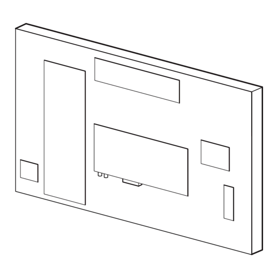
- Page 4 EN 4 LC4.1E AB Technical Specifications, Connections, and Chassis Overview Chassis Overview TOP CONTROL PANEL LCD PANEL TV & SCALER BOARD AMPLIFIER PANEL FRONT IR / LED PANEL SIDE IO PANEL POWER SUPPLY UNIT F_15310_033.eps 270605 Figure 1-5 PWB locations (depending on model)
-
Page 5: Safety Instructions, Warnings, And Notes
Safety Instructions, Warnings, and Notes LC4.1E AB EN 5 2. Safety Instructions, Warnings, and Notes Index of this chapter: Service Default Mode (see chapter 5) with a colour bar 2.1 Safety Instructions signal and stereo sound (L: 3 kHz, R: 1 kHz unless stated 2.2 Warnings... - Page 6 • For sets produced before 1.1.2005, containing leaded soldering tin and components, all needed spare parts will Philips CE is producing lead-free sets (PBF) from 1.1.2005 be available till the end of the service period. For the repair onwards. of such sets nothing changes.
-
Page 7: Directions For Use
Directions for Use LC4.1E AB EN 7 3. Directions for Use You can download this information from the following websites: http://www.philips.com/support http://www.p4c.philips.com... -
Page 8: Mechanical Instructions
EN 8 LC4.1E AB Mechanical Instructions 4. Mechanical Instructions Rear Cover Removal Index of this chapter: 4.1 Service Position 4.2 Rear Cover Removal 4.3 Power Supply Unit Removal 4.4 Small Signal Board Removal 4.5 Side I/O Panel Removal 4.7 LED/IR Panel Removal 4.8 Audio Amplifier Panel Removal... - Page 9 Mechanical Instructions LC4.1E AB EN 9 Small Signal Board Removal Audio Amplifier Panel Removal E_14520_037.eps 160904 E_14520_039.eps 160904 Figure 4-5 Small signal board removal Figure 4-7 Audio amplifier panel removal (depending on model) 1. Disconnect all cables from the Small signal board.
-
Page 10: Service Modes, Error Codes, And Fault Finding
EN 10 LC4.1E AB Service Modes, Error Codes, and Fault Finding 5. Service Modes, Error Codes, and Fault Finding Index of this chapter: For Hotel TV’s, after repair, place the TV set into Hotel (iTV) 5.1 Test Points mode again. Enter the same code on the remote control as 5.2 Service Modes... - Page 11 Service Modes, Error Codes, and Fault Finding LC4.1E AB EN 11 After entering SAM, the following screen is visible, with SAM in After entering SDM, the following screen is visible, with SDM in the upper right corner of the screen to indicate that the the upper right corner of the screen to indicate that the television is in Service Alignment Mode.
- Page 12 EN 12 LC4.1E AB Service Modes, Error Codes, and Fault Finding 12. SC NVM Editor. Can be used to edit Scaler NVM. Upon entering the Customer Service Mode, the following 13. ComPaIr. Can be used to switch on the television to In...
- Page 13 4. Press the MENU LEFT/RIGHT keys to enter the PICTURE Introduction sub menu. ComPair (Computer Aided Repair) is a service tool for Philips 5. Use the MENU UP/DOWN keys to select SHARPNESS. Consumer Electronics products. ComPair is a further 6. Press the MENU LEFT key to decrease the SHARPNESS development on the European DST (service remote control), value.
-
Page 14: Error Codes
EN 14 LC4.1E AB Service Modes, Error Codes, and Fault Finding Specifications Note: If you encounter any problems, contact your local ComPair consists of a Windows based fault finding program support desk. and an interface box between PC and the (defective) product. - Page 15 Service Modes, Error Codes, and Fault Finding LC4.1E AB EN 15 5.5.2 How to Clear the Error Buffer • 9 short blinks followed by a pause of 1.5 seconds, • 6 short blinks followed by a pause of 1.5 seconds, •...
- Page 16 EN 16 LC4.1E AB Service Modes, Error Codes, and Fault Finding 2. If they are present, check RGB output. 3. If there is no RGB output, the IC TDA120xx can be failed. Comb Filter not Working 1. Check the option bit 5 in SAM.
-
Page 17: Block Diagrams, Test Point Overviews, And Waveforms
Block Diagrams, Test Point Overviews, and Waveforms LC4.1E AB 6. Block Diagrams, Test Point Overviews, and Waveforms Wiring Diagram TOP CONTROL 1308 LCD SCREEN (LVDS) CONNECTION Rigth Left Speaker Speaker INVERTER 1706 AUDIO AMPLIFIER BACK (5W) LIGHT CONNECTION LCD SCREEN... -
Page 18: Block Diagram Audio & Video
Block Diagrams, Test Point Overviews, and Waveforms LC4.1E AB Block Diagram Audio & Video HERCULES (IF+VIDEO) TUNER + IF 7011 +5VSW +VTUN TDA120001H1 F312 7014 I044 1328 VIF2 2321 4327 F306 1302 Input R_SDTV Sound CVBS1 7013 VIF1 Tr aps... -
Page 19: Block Diagram Scaler & Supply
Block Diagrams, Test Point Overviews, and Waveforms LC4.1E AB Block Diagram Scaler & Supply SCALER-IO SCALER (ANA IN) SCALER (LVDS, TTL OUT) 1404 1485 F534 HS_PC 7401 PAN_VCC GM5221 B_Pb_PC 7461 G_Y_PC FROM R_SDTV LV_E0_TX0- LV_E0_TX0- R_Pr_OC G_SDTV LV_E1_TX0+ LV_E1_TX0+... -
Page 20: Test Point Overview Ssb (Top Side)
Block Diagrams, Test Point Overviews, and Waveforms LC4.1E AB Test Point Overview SSB (Top Side) F528 B6 SERVICE TESTPOINT F529 B6 F530 B5 F531 B5 F532 B5 F535 B6 F536 B5 F537 B6 F538 B6 F539 B6 I414 B5 I416 B5... -
Page 21: Testpoint Overview Ssb (Bottom Side)
Block Diagrams, Test Point Overviews, and Waveforms LC4.1E AB Testpoint Overview SSB (Bottom Side) F002 C4 F478 E1 I094 B4 I909 A6 F003 B2 F479 E1 I096 B4 I910 B6 F004 A3 F480 E1 I098 A3 I911 B6 F005 D4... -
Page 22: Testpoint Overview Front Ir / Led Panel
Block Diagrams, Test Point Overviews, and Waveforms LC4.1E AB Testpoint Overview Front IR / LED Panel F801 A1 F802 A1 F803 A1 F804 A1 Personal Notes: E_14520_024.eps 3139 123 5836.1 150904 E_06532_012.eps 131004... -
Page 23: I2C Overview
Block Diagrams, Test Point Overviews, and Waveforms LC4.1E AB I2C Overview I2C BUS INTERCONNECTION DIAGRAM HERCULES TUNER IF SCALER (LVDS) +3V3STBY +3V3STBY 3096 3088 F303 +3V3STBY +3V3STBY 7011 3083 PROCESSOR 3084 PART OF VIDEO- F302 PROCESSER 3303 3302 3430 3431... -
Page 24: Supply Voltage Overview
Block Diagrams, Test Point Overviews, and Waveforms LC4.1E AB Supply Voltage Overview TV SUPPLY TUNER + IF SUPPLY SCALER IO PANEL +3V3STBY 1910 (INVERTER) F903 +3V3STBY +5VSW 5520 +5VSW AUD_SUP AUD_SUP 1200 +VTUN +5VSW +VTUN +5VSW F905 +3V3STBY +3V3STBY +3V3STBY... -
Page 25: Circuit Diagrams And Pwb Layouts
Circuit Diagrams and PWB Layouts LC4.1E AB 7. Circuit Diagrams and PWB Layouts SSB: Tuner + VIF 1302 A2 1328 C8 TUNER + IF 1330 D8 1331 C1 1332 B1 2302 D2 1302 2303 D2 With FM UR1316 2307 D3... -
Page 26: Ssb: Hercules (B3)
Circuit Diagrams and PWB Layouts LC4.1E AB SSB: Hercules 1001 G2 3077 D10 I046 H6 1010 A2 3078 F6 I047 G6 HERCULES 2004 B5 3079 F7 I048 H6 2006 G2 3080 G7 I049 G4 2007 G2 3081 G7 I051 G4... -
Page 27: Ssb: Hercules (B2)
Circuit Diagrams and PWB Layouts LC4.1E AB SSB: Hercules Personal Notes: 1006 B1 HERCULES 1007 B1 1008 A1 1684 A1 2001 D3 2012 D1 2024 D1 TO 1308 OF TOP CNTL BD 2067 A2 2082 D3 +3V3STBY +5VSW *EMC 2083 D3... -
Page 28: Ssb: Audio Amplifier + Processing (B4)
Circuit Diagrams and PWB Layouts LC4.1E AB SSB: Audio Amplifier + Processing 1701 A8 1751 D5 2703 C4 AUDIO AMPLIFIER + PROCESSING 2712 B3 2714 A6 2718 B3 2719 A5 AUD_SUP 2724 B5 2736 A7 11V1 2737 B7 2719 2714... -
Page 29: Ssb: Tv Supply (B5)
Circuit Diagrams and PWB Layouts LC4.1E AB SSB: TV Supply 1910 A1 2910 E8 TV-SUPPLY 2911 D9 2920 E3 2921 E4 2930 C3 2931 C6 F903 2933 D7 AUD_SUP *EMC 2934 D4 2936 2936 A2 1910 F904 2937 B2 P_GND... - Page 30 Circuit Diagrams and PWB Layouts LC4.1E AB SSB: Scaler 1403 F4 7401-5 E3 1407 C1 7401-6 A11 SCALER 2401 C8 7401-7 A3 2402 D10 7401-9 E6 2403 D11 7403 C3 +1V8_DVDD +3V3_AVDD 2404 D10 F401 G3 2405 D10 F402 D8...
- Page 31 Circuit Diagrams and PWB Layouts LC4.1E AB SSB: Scaler 1401 A1 I410 C3 1402 C6 I411 B3 SCALER 1404 D8 I412 B3 +3V3_AVDD +3V3_DVDD +3V3_DVDD 1409 A2 I413 C5 2446 C5 I414 C5 7401-8 2448 A8 I416 C5 SC_RESET GM5221...
- Page 32 Circuit Diagrams and PWB Layouts LC4.1E AB SSB: Scaler I/O 1462 A10 F478 A2 1463 A4 F479 A2 SCALER I/O 1485-1 E1 F480 B2 PROVISION FOR DVI-COMB1 1485-2 D1 F481 B2 1463 1485-3 C1 F484 F1 F474 1485-4 B1 F485 E1...
- Page 33 Circuit Diagrams and PWB Layouts LC4.1E AB SSB: Supply 1951 A4 2961 B2 2994 D1 2997 D3 3958 C2 5957 B3 5960 B1 7953 A3 F951 A4 I951 A3 I954 B2 I957 A4 Personal Notes: 2959 A3 2962 A4 2995 D1...
-
Page 34: Ssb: Rear I/O Scart
Circuit Diagrams and PWB Layouts LC4.1E AB SSB: Rear I/O Scart 1101 A1 S104 B1 1102 C5 S105 C1 REAR I/O SCART 2101 A4 S106 C2 2102 A4 S107 C2 2103 B3 S108 D2 2104 B4 S109 D2 2105 B4... -
Page 35: Ssb: Scaler (B6)
Circuit Diagrams and PWB Layouts LC4.1E AB Layout SSB (Top Side) 1001 C3 1302 E2 1407 C6 1751 A3 2012 B2 2030 D4 2050 D4 2060 C3 2307 D3 2372 B3 2380 C4 2387 C4 2394 C4 2421 C5 2450 C6... - Page 36 Circuit Diagrams and PWB Layouts LC4.1E AB Layout SSB (Bottom Side) 1328 C5 2036 D4 2074 B3 2103 E4 2111 E4 2317 D5 2403 C2 2411 C2 2418 D1 2429 C2 2436 D1 2452 C1 2487 E1 2517 C1 2742 B4...
- Page 37 Circuit Diagrams and PWB Layouts LC4.1E AB Side I/O Panel 1101 A1 F112 D8 1102-1 D1 F113 D8 SIDE I/O 1102-2 E1 I101 A7 1102-3 E1 I102 A7 1104 A5 I103 C1 1108 1105 C9 I104 B2 AV3_CVBS_Y_IN I112 1106 B9...
-
Page 38: Side I/O Panel
Circuit Diagrams and PWB Layouts LC4.1E AB Layout Side I/O Panel (Top Side) 1101 A2 1104 A1 1106 A4 1108 A2 1111 A1 2111 A4 1102 A3 1105 A3 1107 A3 1110 A3 1112 A1 2112 A4 F_15310_018.eps 3139 123 5831.2... -
Page 39: Keyboard Control Panel (E)
Circuit Diagrams and PWB Layouts LC4.1E AB Keyboard Control Panel Layout Keyboard Control Panel (Top Side) 1309 A1 1310 A3 1008 D1 1311 A5 KEYBOARD CONTROL 1309 D2 1312 A7 1310 D2 1313 A8 1314 A4 1311 D3 1684 A1... -
Page 40: Top Control Panel (E)
Circuit Diagrams and PWB Layouts LC4.1E AB Top Control Panel Layout Top Control Panel (Top Side) 1308 A1 1309 A6 1310 A5 1311 A3 1312 A2 1313 A4 1684 A1 1308 B1 TOP CONTROL 1309 C2 1310 C2 1311 C3... -
Page 41: Audio Amplifier (I)
Circuit Diagrams and PWB Layouts LC4.1E AB Audio Amplifier 1703 A1 1704 C8 AUDIO AMPLIFIER 1706 C1 1710 E1 2703 D5 2712 B4 2713 B6 2714 B7 2715 B8 2718 B4 2719 B7 2741 B5 2742 C5 AUD_SUP FROM PSU... - Page 42 Circuit Diagrams and PWB Layouts LC4.1E AB Layout Audio Amplifier (Top Side) 1703 A3 2712 A3 2718 A3 2746 A3 3702 A3 3726 A3 3747 A3 3751 A3 4718 A3 7703 A3 Personal Notes: 1704 B2 2713 A1 2719 A1...
-
Page 43: Front Ir / Led Panel (Me5Fl) (J)
Circuit Diagrams and PWB Layouts LC4.1E AB Front IR / LED Panel (ME5FL) Layout Front IR / LED Panel (ME5FL) (Top Side) 1870 B2 6801 A2 7802 A2 7805 A1 7806 A1 1870 B1 3801 B2 3805 D4 6801-1 B4... -
Page 44: Front Ir / Led Panel (26" & 32") (Me5P
Circuit Diagrams and PWB Layouts LC4.1E AB Front IR / LED Panel (26” & 32”) (ME5P) Layout Front IR / LED Panel (26” & 32”) (ME5P) (Top Side) 1870 A1 6801 A3 6805 A3 7802 A2 1870 B1 3802 A4... -
Page 45: Alignments
Press the "MENU" Key on the Wireless Smart-Loader. The Philips Wireless Smart-Loader is an installation tool 2. Wired method (for CRT TVs only): especially designed for easy and fast installation of Philips – Turn on the TV set, connect the Wireless Smart- Institutional TV's. - Page 46 EN 46 LC4.1E AB Alignments 8.4.4 Installing a TV with the Wireless Smart-Loader 8.4.6 Required Software Versions Use a Wireless Smart-Loader programmed with the settings Be aware that the software used in these TV sets is NOT from a master TV of the same type.
- Page 47 Alignments LC4.1E AB EN 47 8.5.3 Hotel Mode Functions This paragraph describes the functionality of each item in the Hotel Mode Setup menu. HOTEL MODE • “OFF”: The Hotel Mode is disabled: (MTV Mode) – The TV set operates as a normal consumer TV.
- Page 48 EN 48 LC4.1E AB Alignments Sam Menu 8.6.1 SAM Menu 00022 LC4CEP1 1.05/S4CEX1 1.06 ERR 0 0 0 0 0 OP 000 057 140 032 120 128 000 . OP1 . Delta Cool Red . OP2 . Delta Cool Green -1 .
- Page 49 NVM Editor, see the text below. Equipment and Setting How to Change an Option Byte • E.g. Fluke 54200 or Philips PM5580. An Option Byte represents a number of different options. • 100% “8-step grey scale” pattern. Changing these bytes directly makes it possible to set all options very fast.
- Page 50 EN 50 LC4.1E AB Alignments Table 8-3 Option Bytes (via Options Menu in SAM or via the Hercules NVM Editor) Bit (DEC) Option 7 (128) msb OP_PHILIPS_TUNER 6 (64) OP_FM_RADIO 5 (32) OP_LNA 4 (16) OP_ATS 3 (8) OP_ACI 2 (4)
- Page 51 Alignments LC4.1E AB EN 51 Table 8-4 Hercules Default NVM Settings (Option Bit Settings via NVM Editor in Sam Mode) All models Byte Nr Feature/Mode Description Byte 0 (LSB) Mode of quasi split sound amplifier 174(dec) Connection of output of QSS amplifier...
-
Page 52: Circuit Descriptions, Abbreviation List, And Ic Data Sheets
EN 52 LC4.1E AB Circuit Descriptions, Abbreviation List, and IC Data Sheets 9. Circuit Descriptions, Abbreviation List, and IC Data Sheets Index of this chapter: • Audio: The sound processor is part of the UOC processor 9.1 Introduction (called “Hercules”). The chassis has a FM Radio with 40 9.2 Block Diagram... - Page 53 3122 137 23071 Tuner and IF On models with FM radio, a Philips UR13xx Tuner with second input (for FM Radio) is used in the TV board. The SIF and FM signals are decoded by the Hercules. Tuning is done via I...
- Page 54 EN 54 LC4.1E AB Circuit Descriptions, Abbreviation List, and IC Data Sheets Video: TV Part (diagrams B1, B2, and B3) when using SM5301BS, Low Pass Filter circuit is Video IF not needed. Otherwise, LPF circuit is needed. Scaler Hercules Analog Input Port...
- Page 55 • The Inter Carrier concept, used in NAFTA and LATAM. The LC4.1E is not equipped with Lip Sync. This is not needed. The UOC-III family makes no difference any more between QSS- and Intercarrier IF, nearly all types are software- Control switchable between the two SAW-filter constructions.
-
Page 56: Abbreviation List
Dynamic RAM : 1366x768 pixels (23”) Digital Signal Processing Luminance : 450 nit Dealer Service Tool: special Supplier : LG.Philips LCD (15”, (European) remote control designed 20”) for service technicians : Quanta Displays Inc. Digital Theatre System (a sound (15”) system, similar to Dolby Digital) : AU Optronics (20”) - Page 57 SandCastle: two-level pulse derived the customers wishes from sync signals LATAM LATin AMerica SC1-OUT SCART output of the MSP audio IC LC04 Philips chassis name for LCD TV 2004 SC2-B-IN SCART2 Blue in project SC2-C-IN SCART2 chrominance in Liquid Crystal Display SC2-OUT...
-
Page 58: Ic Data Sheets
EN 58 LC4.1E AB Circuit Descriptions, Abbreviation List, and IC Data Sheets Variable Level out: processed audio XTAL Quartz crystal output toward external amplifier Luminance signal Video Cassette Recorder YPbPr Component video (Y= Luminance, Pb/ Video Graphics Array Pr= Colour difference signals) - Page 59 Circuit Descriptions, Abbreviation List, and IC Data Sheets LC4.1E AB EN 59 9.11.2 Diagram A2, Type TDA12029H (IC7011) Block Diagram A “ ” o µ & Pin Configuration AVL/SWO/SSIF/ Pin configuration “stereo” and “AV-stereo” versions with Audio DSP REFIN/REFOUT P1.5/TX AUDIOIN5L P1.4/RX...
-
Page 60: Pin Configuration
EN 60 LC4.1E AB Circuit Descriptions, Abbreviation List, and IC Data Sheets 9.11.3 Diagram A12, Type S9993CT (IC7808) Block Diagram RESET# CSDA Registers Slave CSCL DSDA ---------------- Slave Configuration DSCL Logic Block Aux Data Logic HDCP HDCP Block MCLK Keys... -
Page 61: Spare Parts List
2238 586 59812 100nF 20% 50V 0603 2103 4822 126 14241 330pF 0603 50V 2475 2238 586 59812 100nF 20% 50V 0603 e Software (see Philips Service Website) 2104 4822 126 14491 2.2µF 10V 0805 2476 2222 867 15339 33pF 5% 50V 0603... - Page 62 EN 62 LC4.1E AB Spare Parts List 2998 4822 124 40184 1000µF 20% 10V 3391 4822 051 30101 100Ω 5% 0.062W 3745 3198 021 38220 8.2kΩ 5% 0.062W 0603 3394 4822 051 30759 75Ω 5% 0.062W 3751 4822 051 30101 100Ω 5% 0.062W 3401 4822 051 30103 10kΩ...
- Page 63 Spare Parts List LC4.1E AB EN 63 For SW see item number 0611 7402 9322 189 01668 AT24C32AN 7403 9322 205 12671 MX29LV040QC-70G 6101 4822 130 11148 UDZ4.7B 7703 9340 425 20115 BC847BS 7461 9322 199 80668 SM5301BS-G 6102 4822 130 11148 UDZ4.7B...
-
Page 64: Revision List
EN 64 LC4.1E AB Revision List 11. Revision List Manual xxxx xxx xxxx.0 • First release. Manual xxxx xxx xxxx.1 • Hotel Mode (Wireless Smart-Loader) and Hotel Mode Instructions added.
Need help?
Do you have a question about the LC4.1E and is the answer not in the manual?
Questions and answers