Table of Contents
Advertisement
Quick Links
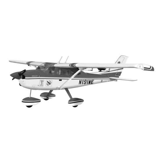
CESSNA 182 SCALE 1:5 ¼ ARF 1.20
SPECIFICATION
- Wingspan: 2075mm (81.7 in)
- Length: 1624mm (64 in)
- Flying weight: 5.6-5.8 kg
- Wing area: 52.6 dm2
- Wing loading: 95g/dm2
- Wing type: Naca airfoils
- Covering type: Genuine ORACOVER®
- Gear type: Aluminum Hi-grade for main gear
and suspension spring wire for nose gear
(included)
- Spinner size: Plastic 70mm (included)
- Radio: 6 channel minimum (not included)
- Servo: 8 standard servo: 2 aileron; 2 flap; 2
elevator; 1 rudder; 1 throttle (not included)
- Recommended receiver battery: 4.8-6V /
1200-2000mAh NiMH (not included)
- Servo mount: 21mm x 42 mm
- Propeller: suit with your engine
- Engine: 1.20/ 2-stroke or 1.40/4-stroke glow
engine or 20-22cc gas engine (not included)
Instruction Manual
- Motor: brushless outrunner 1600-2200 W, 450 KV
(not included)
- Gravity CG: 85 mm (3.3 in) Back from the leading
edge of the wing, at the fuselage
- Control throw Ailerons: Low: 10mm up/down,
10% expo; High: 12mm up/down, 10% expo
- Control throw Elevators: Low: 10mm up/down,
12% expo; High: 12mm up/down, 12% expo
- Control throw Rudder: Low: 30mm right/left, 15%
expo; High: 40mm right/left, 15% expo
- Control throw Flaps: Mid: 15mm down; Landing:
20mm down
- Experience level: Intermediate
- Plane type: Scale Civilian
RECOMMENDED MOTOR AND BATTERY SET UP
- Motor: RIMFIRE .120 (not included)
- Lipo cell: 5-6 cells / 5500 – 6000mAh (not
included)
- Esc: 80-100A (not included)
Advertisement
Table of Contents

Related Manuals for Pheonix Model Cessna 182

Summary of Contents for Pheonix Model Cessna 182
- Page 1 Instruction Manual CESSNA 182 SCALE 1:5 ¼ ARF 1.20 SPECIFICATION - Wingspan: 2075mm (81.7 in) - Motor: brushless outrunner 1600-2200 W, 450 KV - Length: 1624mm (64 in) (not included) - Flying weight: 5.6-5.8 kg - Gravity CG: 85 mm (3.3 in) Back from the leading - Wing area: 52.6 dm2...
-
Page 3: Tools And Supplies Needed
Please trial fit all the parts. Make sure you have the correct parts and that they fit and are aligned properly before gluing! This will assure proper assembly. The CESSNA 182 SCALE 1:5 ¼ ARF 1.20 is hand made TEMPORARY PIN from natural materials, every plane is unique and TO KEEP HINGE minor adjustments may have to be made. -
Page 4: Installing The Aileron Servos
Instruction Manual CESSNA 182 INSTALLING THE AILERON SERVOS 5. Place the aileron servo tray / hatch into the servo box on the bottom of the wing and drill 1. Install the rubber grommets and brass eyelets 1,6mm pilot holes through the tray and the onto the aileron servo. -
Page 5: Installing The Aileron Linkages
Instruction Manual CESSNA 182 2. Attach the clevis to the control horn. Screw 3. Repeat step # 1 - # 2 to install the control horn on the opposite aileron. INSTALLING THE CONTROL HORNS for flap 3. Locate one nylon servo arm, and using wire cutters, remove all but one of the arms. -
Page 6: Installing The Flap Linkage
Instruction Manual CESSNA 182 INSTALLING THE flap LINKAGE 2. Draw a center line onto the horizontal stabilizer. Repeat step #1 - #9 from installing the aileron linkage to install the flap linkage. Remove the covering 3. Check the fit of the horizontal stabilizer. Make... -
Page 7: Vertical Stabilizer Installation
Instruction Manual CESSNA 182 5. Remove the stabilizer. Using the lines you just drew as a guide, carefully remove the covering from between them using a modeling knife. When cutting through the covering to remove it, cut with only enough pressure to only cut through the covering it's self. - Page 8 Instruction Manual CESSNA 182 INSTALLING THE FRONT GEAR 1. Install the wheel pant of the front gear. C.A glue 2. Install the wheels onto the axles using the two wheel collars and set screws provided. The wheels should be centered on the axles with a wheel collar on each side, holding them in place.
-
Page 9: Installing The Wheel Pants
Instruction Manual CESSNA 182 6. With the nose gear wire straight, angle the nylon steering arm about 30 forward of the fire-wall and tighten the set screw. Angling the arm forward like this will allow room for the arm to move back for more adequate steering. -
Page 10: Installing The Motor And Battery
Instruction Manual CESSNA 182 Installing the engine Locate the long piece of wire used for the throttle pushrod. One end of the wire has been pre-bend in to a "Z" bend at the factory. This 35mm "Z" bend should be inserted into the throttle... -
Page 11: Installing The Stopper Assembly
Instruction Manual CESSNA 182 FUEL TANK installation INSTALLING THE STOPPER ASSEMBLY 1. The stopper has been pre-assembled at the factory. 2. Using a modeling knife, cut one length of silicon fuel line (the length of silicon fuel line is calculated by how the weighted clunk should rest about 8mm away from the rear of the tank and move freely inside the tank). -
Page 12: Installing The Elevator Pushrod
Instruction Manual CESSNA 182 8. Feed three lines through the fuel tank compartment and through the pre-drilled hole in Rudder servo the firewall. Pull the lines out from behind the engine, while guiding the fuel tank into place. Push the fuel tank as far forward as possible,... -
Page 13: Installing The Rudder Pushrod
Instruction Manual CESSNA 182 6. Attach clevis to the control horn. 7. Locate one nylon servo arm, and using wire cutters, remove all but one of the arms. Using a 2mm drill bit, enlarge the third hole out from the center to accommodate the elevator pushrod wire. -
Page 14: Installing The Throttle
Instruction Manual CESSNA 182 6. Attach clevis to the control horn. 7. Locate one nylon servo arm, and using wire cutters, remove all but one of the arms using a 2mm drill bit, enlarge the third hole out from the center to accommodate the rudder pushrod wire. -
Page 15: Mounting The Cowl
Instruction Manual CESSNA 182 Throttle servo Screw MOUNTING THE COWL 1. Remove the muffler and needle valve assembly from the engine. Slide the fiberglass cowl over the engine. 2. Measure and mark the locations to be cut out for engine head clearance, needle valve, muffler. -
Page 16: Installing The Switch
Instruction Manual CESSNA 182 INSTALLING THE SWITCH 1. The switch should be mounted on the fuselage side, opposite the muffler, close enough to the receiver so the lead will reach. Use the face plate of the switch cut out and locate the mounting holes. -
Page 17: Installing The Door
Instruction Manual CESSNA 182 4. Screw the door. Pilots Screw INSTALLING THE DOOR 1. Glue the velcro to the pannel. BALANCING 1. It is critical that your airplane be balanced correctly. Improper balance will cause your plane to lose control and crash. -
Page 18: Lateral Balance
Instruction Manual CESSNA 182 LATERAL BALANCE After you have balanced a plane on the C.G. You should laterally balance it. Doing this will help the airplane track straighter. 1. Turn the airplane upside down. Attach one loop of heavy string to the engine crankshaft and one to the tail wheel wire. - Page 19 I/C FLIGHT WARNINGS...
- Page 20 I/C FLIGHT GUIDELINES Operate the control sticks on the When ready to fly, first extend the transmitter and check that the control transmitter aerial. surfaces move freely and in the ALWAYS land the model INTO the CORRECT directions. wind, this ensures that the model lands at the slowest possible speed.
Need help?
Do you have a question about the Cessna 182 and is the answer not in the manual?
Questions and answers