
Related Manuals for Sunny P8300


Summary of Contents for Sunny P8300
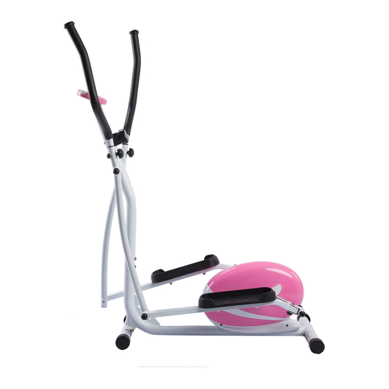
- Page 1 Pink Magnetic Elliptical Bike Model No. P8300 IMPORTANT! PLEASE READ THIS MANUAL CAREFULLY BEFORE USING THE BIKE. For Customer Service, please contact: support@sunnyhealthfitness.com...
-
Page 2: Important Safety Information
IMPORTANT SAFETY INFORMATION We thank you for choosing our product. To ensure your safety and health, please use this equipment correctly. It is important to read this entire manual before assembling and using the equipment. Safe and effective use can only be achieved if the equipment is assembled, maintained and used properly. -
Page 3: Exploded View
EXPLODED VIEW... -
Page 4: Parts List
PARTS LIST Description Qty. Description Qty. Main frame Sensor wire Rear stabilizer Φ50 Trunk wire Adjustable end cap Φ50 Tension wire Carriage bolt M10*60 Ball cap S13 Arc washer d10*Φ25*2*R30 Nylon nut R B0.5 Alloy bushing Φ14*Φ10.1*10 Nut M10 Front stabilizer Φ50 Bushing Φ28.5*Φ15.5*23 Bushing with chamfer End cap Φ50... -
Page 5: Hardware Package
HARDWARE PACKAGE... -
Page 6: Assembly Instructions
ASSEMBLY INSTRUCTIONS Step 1: Attach Front Stabilizer (7) and Rear Stabilizer (2) to Main Frame (1) and tighten with 4 sets Carriage Bolts (4), Arc Washers (5) and Nuts (6). - Page 7 Step A. Connect Trunk Wire (28) to Sensor Wire (27). Then connect 8-Level Tension Controller (35) with Tension Wire (29). CAUTION: Please make sure the 8-Level Tension Controller (35) is at the lowest resistance level (level 1, all the way to the left) before you connect the Tension Control cable. B.
- Page 8 Step A. Lock Swing Rod (24L/R) to Handlebar Post (36) with Nuts (31), and Washers (16), then attach Ball Caps (18). B. Lock Connecting Rod (22L/R) to Main Frame (1) with Hinge Bolts (11L/R), Wave Washers (49), Spring Washers (42), and Nuts (17L/R), then cover with Ball Caps (18) and Ball Caps (9). CAUTION: Part 11 is labeled L for LEFT and R for RIGHT.
- Page 9 ALTERNATE INSTALLATION METHOD: Step 1 Disconnect the Link Connector Combination (13L/R) from the Connecting Rod (22L/R). Step 2 Insert the Hinge Bolt (11L/R) through the Wave Washer (49), then through the hole of the Link Connector Combination (13L/R), then screw the Hinge bolt into crank arm.
- Page 10 Step 4: Insert Handlebar (46 L/R) into Swing Rod (24L/R) and tighten with Knobs (38), then cover with Ball Caps (30).
- Page 11 Step 5: Attach Pedal (21L/R) to Connecting Rod (22L/R) and tighten with Bolts (20) and Washers (14) and Nuts (15).
- Page 12 Step 6: Connect Trunk Wire (28) to Computer Wire (43a). Fix Computer (43) to computer holder on the top of Handlebar Post (36) with Screws (41). Assembly finished!
-
Page 13: Functional Buttons
EXERCISE COMPUTER INSTRUCTION MANUAL FUNCTIONAL BUTTONS: MODE – Press to select functions. – Press and hold the MODE button for 3 seconds to reset time, distance and calories. SET(If Available)– Press to set values of time, pulse, distance and calories when not in scan mode. A. -
Page 14: Battery Replacement
BATTERY REPLACEMENT The batteries are located on the back of the computer. To replace the batteries, open the battery cover. Remove the batteries. Replace with new batteries. Make sure the (-) end of the battery goes to the spring end in the battery compartment.
Need help?
Do you have a question about the P8300 and is the answer not in the manual?
Questions and answers