Table of Contents
Advertisement
Quick Links
Advertisement
Table of Contents

Related Manuals for Sunny SF-E3416H


Summary of Contents for Sunny SF-E3416H
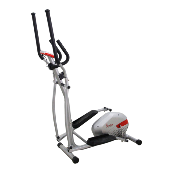
- Page 1 MAGNETIC ELLIPTICAL TRAINER WITH TABLET HOLDER SF-E3416H USER MANUAL IMPORTANT: Please read this manual carefully before using the product. Retain owner’s manual for future reference. For Customer Service, please contact: support@sunnyhealthfitness.com...
-
Page 2: Important Safety Information
IMPORTANT SAFETY INFORMATION We thank you for choosing our product. To ensure your safety and health, please use this equipment correctly. It is important to read this entire manual before assembling and using the equipment. Safe and effective use can only be achieved if the equipment is assembled, maintained and used properly. -
Page 3: Exploded Drawing
EXPLODED DRAWING 1 30 36 S13-14-15 S17-19... - Page 4 EXPLODED DRAWING 2...
-
Page 5: Parts List
PARTS LIST Description Qty No. Description Computer U shape plate Arc washer Φ25*Ф6*3.3*R25.2 Middle handlebar Foam grip Φ23*5*445 Washer d8*Φ16*1.5 End cap Φ25*16 Nylon nut L M8*H7.5*S13 Washer d6*Φ12*1 Wave washer d19*Φ25*0.3 Hinge bolt R Φ16*89*23*1/2*S8 Screw ST4*19 Handle pulse sensor Φ25 End cap J40*25*15 Screw M8*30*S6 Clamp cover 71*58*40... - Page 6 Description Description Spanner S13-14-15 1 94 Bolt M6*12*S10 Spanner S17-S19 (inner 17) 1 95 Washer d6*Φ16*1.5 Wave washer d17*Φ25*0.3 2 96 Bolt M6*10*S10 Computer wire 1 97 Fixing plate t1.5*56*76 1 98 Screw M8*35*18*S6 Bearing 6001-2RS Bearing seat Φ72*11 Tablet mounting bar 270*190*3 1 99 Screw M5*12*Φ10 Inertia axle Φ20*103...
-
Page 7: Hardware Package
HARDWARE PACKAGE... -
Page 8: Assembly Instructions
ASSEMBLY INSTRUCTIONS #19 M8*H16*S13 4pcs #28 M8*60*20*H5 4pcs #29 d8*Φ20*2*R30 4pcs STEP 1: Attach the Front and Rear Stabilizers (No. 27 and No. 65) to the Main Frame (No. 59) using 4 Carriage Bolts (No. 28), 4 Arc Washers (No. 29) and 4 Cap Nuts (No. 19), tighten and secure with Spanner (No. - Page 9 #53 M8*16*S6 4pcs #29 d8*Φ20*2*R30 4pcs #67 S6 FIG. 1 FI G . 1 29 53 FIG. 2 FI G . 2 STEP 2: IMPORTANT: Before attempting to connect the Upper Tension Wire (No. 52B). Ensure that the Tension Control Knob (No. 52A) is turned all the way to the left (the lowest level of resistance), this will provide the tension cable with the necessary length required to connect it.
- Page 10 #24 M8*16*S14 2pcs #22 d8*Φ32*2 2pcs #23 d8 2pcs #70 d17*Φ25*0.3 2pcs #49 1/2" 2pcs #66 S8 #48 1/2*20*H8*S19 R 1pc #50 1/2*20*H8*S19 L 1pc #60 S13 6PCS #62 S16 2PCS #61 S18 2PCS IMPORTANT: When installing, please ensure that the stickers marked with L and R on the Swing Rods of 25L &...
- Page 11 ALTERNATE INSTALLATION METHOD: NOTE: The alternate installation method is highly recommended for users having difficulty when installing Hinge Bolt L (No. 45) and Hinge Bolt R (No. 40). STEP 1: Disconnect Link Connector Combination (No. from Connecting Rod (No. 55). STEP 2: Insert Hinge Bolt L (No.
- Page 12 #37 d8*Φ16*1.5 4pcs #38 M8*H7.5*S13 4pcs #17 M8*40*20*S14 4pcs STEP 4: Attach the left and right Pedals (No. 43L and No. 43R) to the Connecting Rods (No. 55) using 4 Bolts (No. 17), 4 Washers (No. 37) and 4 Nylon Nuts (No. 38). Tighten and secure with Spanner (No.
- Page 13 #19 M8*H16*S13 2pcs #18 d8*Φ20*2*R16 2pcs #17 M8*40*20*S14 2pcs STEP 5: Insert the left and right Handlebars (No. 13L & No. 13R) into the tops of left and right Swing Rods (No. 25L & No. 25R). Fix using 2 Bolts (No. 17), 2 Arc Washers (No. 18) and 2 Cap Nuts (No.
- Page 14 #8 M8*30*S6 2pcs #23 d8 2pcs #37 d8*Φ16*1.5 1pc #38 M8*H7.5*S13 1pc #42 71*58*40 1pc #72 M8*35*18*S6 1pc #74 M5*12*Φ10 2pcs FIG. 1 FI G . 1 FI G . 2 FIG. 2 STEP 6: Connect the Upper Sensor Wire (No. 10) to the Computer Wire (No. 71). Ensure that the connection is properly secured before continuing.
-
Page 15: The Display Console
THE DISPLAY CONSOLE Our computerized display console on the Sunny Magnetic Elliptical Trainer allows the user to tailor a personalized workout by monitoring their progress. During a workout, the display console will alternately and repeatedly display your Time, Speed, Distance, Calories, and Pulse. - Page 16 TABLET HOLDER ADJUSTMENTS The viewing angle of Tablet Holder (No. 15) can be adjusted manually without a knob. The Tablet Holder (No. 15) can be adjusted from a 6 degree angle to a 53 degree viewing angle as shown in Fig. A and Fig. B. WARNING! The Tablet Holder (No.
- Page 17 EXERCISE PROCEDURES NOTE: The Sunny Magnetic Elliptical Trainer provides you with various benefits. Striding helps to improve your physical fitness by increasing your cardiovascular endurance, and tone your body. If paired with a calorie controlled diet, it can also help you lose weight.
Need help?
Do you have a question about the SF-E3416H and is the answer not in the manual?
Questions and answers