Table of Contents
Advertisement
Advertisement
Table of Contents

Related Manuals for Grundfos RSI Series


Summary of Contents for Grundfos RSI Series
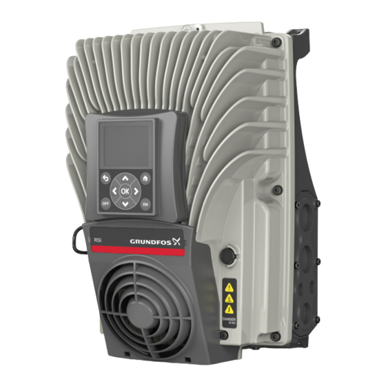
- Page 1 GRUNDFOS INSTRUCTIONS RSI, 1.5 - 37 kW Installation and operating instructions...
-
Page 2: Table Of Contents
Warning If any deviation from the order is found, please Prior to installation, read these installation contact Grundfos. Once you get the product, please and operating instructions. Installation and perform the following inspections before installation: operation must comply with local... -
Page 3: Technical Data
3. Technical data 3.1 Product range 3.1.1 Dimensions Frame A 1.5 - 5,5 kW Fig. 1 Product Frame Size Net weight [kg] [mm] [mm] [mm] [mm] [mm] [mm] [mm] [mm] [mm] ∅5.9 Frame A 143.5 191.0 297.0 293.0 315.0 188.0 197.0 214.0 Package... - Page 4 Frame B 7.5 - 15 kW Fig. 2 Product Frame Size Net weight [kg] [mm] [mm] [mm] [mm] [mm] [mm] [mm] [mm] [mm] ∅6.1 Frame B 14.9 180.0 233.0 349.0 345.2 368.0 204.0 214.0 231.0 Package Frame Size Gross weight Length Width Height...
- Page 5 Frame C 18,5 - 37 kW Fig. 3 Product Frame Size Net weight [kg] [mm] [mm] [mm] [mm] [mm] [mm] [mm] [mm] [mm] ∅8.2 Frame C 31.5 322.0 350.0 385.0 382.5 500.0 230.0 236.0 254.0 Package Frame Size Gross weight Length Width Height...
-
Page 6: Technical Data
3.2 Technical data Voltage 3 x 208-240 V 3 x 380-415 V Min. ambient temperature [°C] Installation Max. ambient temperature [°C] environment Max. relative humidity Min. recommended MPP voltage [VDC] Max. Input voltage [VDC] Min. frequency [Hz] Max. frequency [Hz] Electrical data Phases Rated output voltage... -
Page 7: Installation
4. Installation To ensure a good convective cooling Warning effect, install the inverter vertically with at Installation must be carried out by qualified least 10 cm free space at the top and staff. Caution bottom. To be installed indoors. Do not install the You must adjust the minimum frequency to Caution equipment in direct sunlight. -
Page 8: Electrical Connection
4.2 Electrical connection Warning To avoid arcing and fire, tighten all terminals with the specified torque. To avoid the risk of electric shock or fire, Caution make sure that the power supply has been For distances (pump to inverter) exceeding cut off before connecting the equipment. -
Page 9: Operation
5. Operation Warning Check all electrical connections before powering up the system. Warning The heat sink becomes hot during running and stays hot for a long time. Touching it while it is hot will cause burns. In case of altitudes over 1000 m, the Caution output current should be reduced by 10 % for every 1500 m increase in altitude. - Page 10 Indicator lights and keys Function description Off key Turns the inverter output OFF. On key Turns the inverter output ON. Up key Navigate control panel and edit parameter values. Down key Navigate control panel and edit parameter values. Right key Navigate control panel and edit parameter values.
-
Page 11: Control Panel Operation
5.2 Control panel operation 5.2.1 Grundfos start-up wizard Display Directions Notes Select Language Select Start up Wizard Verify or adjust the rated motor voltage Verify or adjust the rated frequency Verify or adjust the nominal speed Verify or adjust the rated current... - Page 12 Display Directions Notes Select pump type or Other and adjust parameters Select solar modules or other and adjust Vmp (maximum power voltage) Select the number of solar modules Select if sinus filter is used or not...
-
Page 13: Quick Setup Parameter Description
Motor Cos Phi Motor Power Factor Size Dependent Motor Nom Power Motor Rated Power Size Dependent Pump Selection Grundfos Pump Family Min Freq Reference Lower frequency Max Freq Reference Target frequency Acceleration time Initial ramp time Deceleration time Final ramp time... -
Page 14: Fault Finding
6. Fault finding 6.1 Fault codes and remedies Fault Fault Fault name Possible cause Remedy code Overcurrent AC drive has detected too high a Check loading. (hardware fault) current (> 4*I ) in the motor cable: Check motor. • sudden heavy load increase Check cables and connections. - Page 15 Fault Fault Fault name Possible cause Remedy code Communication between control board and power unit has failed. Communication between control board and power unit has interference, but it is still working. Reset the fault and restart. Watchdog has reset the CPU Should the fault re-occur, contact the distributor near to Voltage of auxiliary power in power...
- Page 16 Fault Fault Fault name Possible cause Remedy code Brake chopper Check brake resistor and supervision No brake resistor installed. cabling. (hardware fault) Brake resistor is broken. If these are ok, the chopper is Brake chopper failure. faulty. Contact the distributor Brake chopper near to you.
- Page 17 Fault Fault Fault name Possible cause Remedy code Option board changed for one Device changed previously inserted in the same slot. Device is ready for use. Old (same type) The board's parameter settings are parameter settings will be used. saved. Option board added.
- Page 18 Fault Fault Fault name Possible cause Remedy code Actual status of mechanical brake Check the status and remains different from the control Mechanical brake connections of the mechanical 1058 signal for longer than what is brake. defined. Check settings and water level Low water level The minimum water level is not ok.
- Page 19 Fault Fault Fault name Possible cause Remedy code Input pressure supervision signal Check the process. 1109 has gone below the alarm limit. Input pressure Check the parameters supervision Check the input pressure sensor Input pressure supervision signal 1409 and connections. has gone below the fault limit.
-
Page 20: Fault Codes Reset
6.2 Fault codes reset 7. Service and maintenance When a fault appears and the RSI stops, examine Warning the cause of fault, perform the actions advised in section 6.1 and reset the fault as instructed below. Maintenance and inspection must be performed by a qualified electrician. - Page 21 7.1.2 Main inspection and maintenance points Inspection frequency Inspection issue Inspection item Criteria or requirements Routine Regular 1. Temperature. 1. Temperature < 50 °C. 2. Humidity. 2. Humidity < 90 %, no Running condensation. √ 3. Gas. environment 3. No flammable, explosive gas. 4.
-
Page 22: Inspection And Replacement Of Wear Parts
This product or parts of it must be disposed of in an environmentally sound way: 1. Use the public or private waste collection service. 2. If this is not possible, contact the nearest Grundfos company or service workshop. Subject to alterations. - Page 24 Argentina China Hong Kong Bombas GRUNDFOS de Argentina S.A. GRUNDFOS Pumps (Shanghai) Co. Ltd. GRUNDFOS Pumps (Hong Kong) Ltd. Ruta Panamericana km. 37.500 Centro 10F The Hub, No. 33 Suhong Road Unit 1, Ground floor Industrial Garin Minhang District Siu Wai Industrial Centre 1619 Garín Pcia.
- Page 25 Malaysia Serbia Turkey GRUNDFOS Pumps Sdn. Bhd. Grundfos Srbija d.o.o. GRUNDFOS POMPA San. ve Tic. Ltd. 7 Jalan Peguam U1/25 Omladinskih brigada 90b Sti. Glenmarie Industrial Park 11070 Novi Beograd Gebze Organize Sanayi Bölgesi 40150 Shah Alam Phone: +381 11 2258 740...
- Page 26 98464145 0516 ECM: 1184037 www.grundfos.com...
Need help?
Do you have a question about the RSI Series and is the answer not in the manual?
Questions and answers