Grundfos RSI Installation And Operating Instructions Manual
1.5-250 kw 2-340 hp solar application
Hide thumbs
Also See for RSI:
- Installation and operating instructions manual (144 pages) ,
- Safety instructions and other important information (19 pages) ,
- Booklet (16 pages)

Subscribe to Our Youtube Channel
Related Manuals for Grundfos RSI


Summary of Contents for Grundfos RSI
- Page 1 GRUNDFOS INSTRUCTIONS RSI, 1.5-250 kW (2-340 hp) SOLAR APPLICATION Installation and operating instructions...
- Page 3 RSI, 1.5-250 kW (2-340 hp) English (GB) Installation and operating instructions ........4...
-
Page 4: Table Of Contents
Original installation and operating instructions Table of contents Grundfos RSI....5 Specific functions of Grundfos RSI ..5 Safety ..... 6 Danger . -
Page 5: Grundfos Rsi
The dedicated application software was developed to (keypad) and Remote control place. The remote drive a Solar Pump with an optimized MPPT control place is selectable by parameter (I/O or (Maximum Power Point Tracking) for RSI supplied by Fieldbus) Solar Panels. •... -
Page 6: Safety
Death or serious personal injury or connected appliances. ‐ The touch current of RSI exceeds 3.5 Before installing, commissioning or using the mA AC. According to standard frequency converter, please read the warning EN61800-5-1, a reinforced protective information contained in RSI Installation Manual. -
Page 7: Receiving The Product
Weights of RSI drives (A-C) Weight Enclosure size [kg] [lb] 19.4 14.9 32.8 31.5 69.4 Weights of RSI wall-mounted drives (MR4-MR9) Weight Enclosure size [kg] [lb] 13.2 10.0 20.0 20.0 44.1 37.5 82.7 66.0... - Page 8 Weights of RSI drive modules (MR8-MR10) Weight Enclosure size or item [kg] [lb] MR8 IP00 drive module MR9 IP00 drive module MR10 IP00 drive module MR10 IP00 drive module and the options module with the brake chopper MR10 IP00 drive module and the options module with the brake chopper and...
- Page 9 3. Put the lifting hooks symmetrically in a minimum of 2 holes. 4. The maximum lifting angle is 45°. 3.1.3 Lifting RSI drive module MR10 without options Lifting RSI drive module MR10 without options 1. Remove the drive from the package.
-
Page 10: Installation
3.1.4 Lifting RSI drive module MR10 with an options module ≤60° Lifting RSI drive module MR10 with an options module 1. Remove the drive from the package. 2. Use a lifting device that is sufficiently strong for the weight of the drive. -
Page 11: Ventilation
Ambient temperature up to 60 °C (140 °F). must exceed 3.5 mA. • The RSI drive must be hung directly on the wall or If RSI is connected to an electrical installation where fitted with a back plate. an earth leakage circuit breaker (ELCB/RCD) is used... -
Page 12: Dc Fuse Selection
4.5 DC fuse selection multiple strings are connected in parallel. See chapter 4.6 Manufacturers of gPV fuses for recommended The fuses on the DC-Input of the inverter must have gPV fuse manufacturer. the following characteristics: The photovoltaic fuses have to meet the IEC 60269-6 Fuse characteristics or the UL 2579 standard. -
Page 13: Manufacturers Of Gpv Fuses
Recommended fuse sizes, Mains voltage 3AC 380-480/500 V, 50/60 Hz, up to 800 V in V DC Rated IEC60269-6 UL-2579 Fuse continuous Total number of Fuse size size Enclosure size AC drive type current fuses 0003 0004 0005 0008 0009 0012 12.0 0016... -
Page 14: Parallel Diode Selection
4.7 Parallel diode selection When RSI A-C or RSI MR5-MR10 is used in the Solar Pump application, a diode must be connected between DC+ and DC- to protect the inverter against reverse voltage. See tables below for diode specification. Diode specification, Mains voltage 3AC 208-240 V, 50/60 Hz, up to 400 V in V DC... - Page 15 Diode specification, Mains voltage 3AC 380-480/500 V, 50/60 Hz, up to 800 V in V DC AC drive Diode specifications Min. IFav Min. Voltage rating Max. Vf [V] Enclosure size AC drive type @ IFav [A] 0003 0004 0005 0008 0009 0012 0016...
-
Page 16: Photovoltaic System Dimensioning
The photovoltaic system has to be dimensioned in order to not exceed the values specified in the tables below. The RSI enclosure sizes are A-C and MR5- MR10. AC drive (208-240 V 3AC 50/60 Hz, up to 400 V DC) DC-link input ratings Max. - Page 17 AC drive (380-480/500 V 3AC 50/60Hz, up to 800 V DC) DC-link input ratings Max. PV input Maximum recommende operating DC supply operating PV (absolute Enclosure d PV array voltage AC drive type input current maximum) size [V DC] power range [A DC] [V DC]...
-
Page 18: Power Ratings
4.9 Power ratings AC drive (208-240 V 3AC 50/60 Hz, up to 400 V DC) output ratings Power Current Max. (maximu Frequenc Max. Current Voltage (maximu output output Power (inrush) (nominal over Enclosure AC drive continuou (nominal fault factor or range) continuou current size... - Page 19 AC drive (380-480/500 V 3AC 50/60 Hz, up to 800 V in VDC) output ratings Power Current Max. (maximu Frequenc Max. Current Voltage (maximu output output Power (inrush) (nominal over Enclosure AC drive continuou (nominal fault factor or range) continuou current size type...
-
Page 20: Grounding
In this case, there is no possibility to have any control until the drive is discharged. if AC or DC supply is used for energy source. Supply The minimum AC-DC switchover delay is 30 s for RSI always comes automatically from the source where A-C and RSI MR5-MR6. -
Page 21: External +24 V Supply
P3.5.1.60, to tell contactor status. The external DC switch must comply with Australian 4.11.4 Overvoltage category regulations, particularly with AS 60947.3:2018. The overvoltage category of the AC drive is Category III. RSI A-C drives Example of the power connections: A/B... - Page 22 Example of the power connections: C RSI MR5-MR10 drives L1 L2 L3 DC- DC+ R- U V W Example of the power connections: MR5-MR7...
- Page 23 DC- DC+ Example of the power connections: MR8 U V W L1 L2 L3 DC-R+R- Example of the power connections: MR9...
- Page 24 DC+ DC- U/T1 V/T2 W/T3 Example of the power connections: MR10 without extension box DC+ DC- Example of the power connections: MR10with extension box Pos. Description DC switch DC fuses DC power supply protection diode...
-
Page 25: Startup
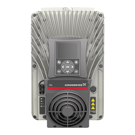
5. Startup 5.1 Operating panel Operating panel Pos. Description Display Scroll menu up Increase value Move backward in menu Exit edit mode Reset faults with long press Move cursor left Stop button Enter active level/item Confirm selection Change control place Access control page Change direction Move cursor right... -
Page 26: Startup Wizard Parameter Description
5.2 Startup wizard parameter description You can have your AC drive equipped with Once you have connected power to your RSI, follow a graphical keypad. these instructions to easily set up your drive. Name Description Factory setting User setting Language Selection... -
Page 27: Description Of The Applications
In the Quick Setup parameter group you will find the Use the parameter P1.2 (Application) to make a different wizards of the RSI Solar Pump Application. selection of an application for the drive. Immediately The wizards help you to quickly set up your drive for when the parameter P1.2 changes, a group of... - Page 28 Code Parameter Unit Default Description The identification run calculates or measures the motor parameters that are necessary for a good control of the motor and speed. 0 = No action P1.15 Identification 1 = At standstill 2 = With rotation Before you do the identification run, you must set the motor nameplate parameters.
- Page 29 Code Parameter Unit Default Description Selection of ref source when control place is Fieldbus: P1.24 Fieldbus Ref sel See P1.22 0 = 0…10 V / 0…20 mA P1.25 AI1 signal range 1 = 2…10 V / 4…20 mA 0 = 0…10 V / 0…20 mA P1.26 AI2 signal range 1 = 2…10 V / 4…20 mA...
- Page 30 Code Parameter Unit Default Description 44 = Block Out.1 45 = Block Out.2 46 = Block Out.3 47 = Block Out.4 48 = Block Out.5 49 = Block Out.6 50 = Block Out.7 51 = Block Out.8 52 = Block Out.9 53 = Block Out.10 54 = No function 55 = No function...
- Page 31 5.3.1 Standard application You can use the Standard application in speed- references available. You can activate the preset controlled processes where no special functions are frequency references with DI4 and DI5. The start/stop necessary, for example pumps, fans, or conveyors. signals of the drive are connected to DI1 (start forward) and DI2 (start reverse).
- Page 32 5.3.2 Local/Remote application For each control place, you can make a selection of the frequency reference from the keypad, Fieldbus or Use the Local/Remote application when, for example, I/O terminal (AI1 or AI2). it is necessary to switch between 2 different control It is possible to configure all the drive outputs freely in places.
- Page 33 M1.33 Multi-step speed Code Parameter Min Max Unit Default ID Description P1.33.1 Preset Freq 1 P1.3 P1.4 10.0 P1.33.2 Preset Freq 2 P1.3 P1.4 15.0 P1.33.3 Preset Freq 3 P1.3 P1.4 20.0 P1.33.4 Preset Freq 4 P1.3 P1.4 25.0 P1.33.5 Preset Freq 5 P1.3 P1.4 30.0...
- Page 34 Code Parameter Unit Default Description 0 = Not used 1 = AI1 2 = AI2 3 = AI3 4 = AI4 5 = AI5 6 = AI6 7 = ProcessDataIn1 8 = ProcessDataIn2 9 = ProcessDataIn3 10 = ProcessDataIn4 11 = ProcessDataIn5 P1.34.4 FB 1 Source 12 = ProcessDataIn6...
- Page 35 Code Parameter Unit Default Description 0 = Not used 1 = Keypad setpoint 1 2 = Keypad setpoint 2 3 = AI1 4 = AI2 5 = AI3 6 = AI4 7 = AI5 8 = AI6 9 = ProcessDataIn1 10 = ProcessDataIn2 11 = ProcessDataIn3 12 = ProcessDataIn4...
- Page 36 5.3.5 Multi-purpose application There are 2 acceleration/deceleration ramps available. The selection between Ramp1 and Ramp2 You can use the Multi-purpose application for different is made by DI6. processes (for example conveyors) where a wide It is possible to configure all the drive outputs freely in range of motor control functions is necessary.
- Page 37 Code Parameter Unit Default Description Defines the current injected into the motor during DC-braking. P1.35.14 DC Brake Current Varies Varies Varies 0 = Disabled Determines if braking is ON or OFF and P1.35.15 DC BrakeTime 0,00 600,00 0,00 the braking time of the DC-brake when the motor is stopping.
-
Page 38: User Interfaces
6.1 Keypad of the drive functions. On the display, the user sees information The control keypad is the interface between the RSI about the drive and his present location in the menu and the user. With the control keypad it is possible to structure and the item displayed. - Page 39 6.1.4 RSI graphical keypad STOP READY Main Menu Quick Setup ( 17 ) Monitor ( 5 ) Parameters ( 12 ) Main menu Pos. Description Status field STOP/RUN Direction Status field READY/NOT READY/FAULT ALARM Control place PC/IO/KEYPAD/FIELDBUS Location field...
- Page 40 6.1.5 Using the graphical keypad 6.1.5.1 Editing values The selectable values can be accessed and edited in two different ways on the graphical keypad. 1. Parameters with one valid value Typically, one parameter is set one value. The value is selected either from a list of values (see example below) or the parameter is given a numerical value from a defined range (e.g.
- Page 41 Typical editing of values on graphical keypad (numerical value) 2. Parameters with check box selection Some parameters allow selecting several values. Make a check box selection at each value you wish to activate as instructed below. Applying the check box value selection on graphical keypad Pos.
- Page 42 • Remote control place 6.1.5.5 Changing control places I/O A, I/O B and Fieldbus can be used as remote Change of control place from Remote to Local control places. I/O A and Fieldbus have the lowest (keypad). priority and can be chosen with parameter P3.2.1 1.
- Page 43 STOP READY STOP Ready Keypad STOP READY Keypad Choose action Keypad Reference Keypad Main Menu ID:1805 ID:184 Monitor 0.00 Hz 0.00 Hz Change direction ( 7 ) Control page Parameters Output Frequency Output Frequency Motor Torque Motor Torque Local/Remote ( 15 ) 0.00Hz...
- Page 44 6.1.5.9 Copying parameters 1. First go into User settings menu and locate the Parameter backup submenu. In the Parameter backup submenu, there are three possible This feature is available in graphical functions to be selected: keypad only. 2. Restore factory defaults will re-establish the parameter settings originally made at the factory.
- Page 45 6.1.5.10 Help texts The graphical keypad features instant help and information displays for various items. All parameters offer an instant help display. Select Help and press the OK button. Text information is also available for faults, alarms and the startup wizard. STOP READY STOP...
-
Page 46: Grundfos Pc Tool
6.2 Grundfos PC tool The PC tool is for commissioning and maintenance of the RSI. Grundfos PC tool is an accessory available in Grundfos Product Center. Menu structure Click on and select the item you wish to receive more information about (electronic manual). - Page 47 6.2.2 Monitor In the Quick Setup parameter group you will find the Multi-monitor different wizards of the Grundfos RSI. More detailed On the multi-monitor page, you can collect four to information on the parameters of this group you will nine values that you wish to monitor.
- Page 48 6.2.3 Parameters 6.2.4 Diagnostics Through this submenu, you can reach the application Under this menu, you can find Active faults, Reset parameter groups and parameters. faults, Fault history, Total counters, Trip counters Software info. Related information 8. Parameters Active faults Menu Function Note The fault remains active until it is cleared...
- Page 49 Trip counters Code Parameter Unit Default Description Resettable energy counter. Note: The highest energy unit shown on the standard keypad is MW. Should the counted energy exceed 999.9 MW, no unit is shown P4.5.1 Energy trip counter Varies 2296 on the keypad. To reset the counter: Graphical keypad: Push OK once.
- Page 50 6.2.5 I/O and hardware Various options-related settings are located in this menu. Note that the values in this menu are raw values i.e. not scaled by the application. Basic I/O Monitor here the statuses of inputs and outputs. Code Parameter Unit Default Description...
- Page 51 Given the standard I/O board compilation on the RSI, there are 6 digital inputs available (Slot A terminals 8, The programming of inputs in the RSI is very flexible. 9, 10, 14, 15 and 16). In the programming view, these...
- Page 52 Input type Slot Input # Explanation (Graphical keypad) Digital input #4 (terminal 14) on board in Slot A DigIN (standard I/O board). Digital input #5 (terminal 15) on board in Slot A DigIN (standard I/O board). Digital input #6 (terminal 16) on board in Slot A DigIN (standard I/O board).
- Page 53 Programming instructions Graphical keypad 1. Select the parameter and push the Arrow right button. 2. You are now in the Edit mode as the slot value DigIN SlotA. is blinking and underlined. (Should you have more digital inputs available in your I/O, for example, through inserted option boards in slots D or E, they can also be selected here.).
- Page 54 Parameter value (= Function) Parameter value (= selected digital input) Given the standard I/O terminals on the RSI, there are 2 analogue inputs available. In the programming view, these inputs are referred to as follows: Input type...
- Page 55 Number (#) refers to Control Word bit number. FieldbusPD.# Number (#) refers to Process Data 1 bit number. Default assignments of digital and analogue inputs in RSI Digital and analogue inputs are assigned certain functions by the factory. In this application, the default assignments are:...
- Page 56 Input Terminal(s) Reference Assigned function Parameter code External fault close P3.5.1.13 AI1 signal selection P3.5.2.1.1 AI2 signal selection P3.5.2.2.1 Real time clock Code Parameter Unit Default Description Status of battery. 1 = Not installed V5.5.1 Battery state 2205 2 = Installed 3 = Change battery P5.5.2 Time...
- Page 57 Sine filter Code Parameter Unit Default Description 0 = Disabled V5.6.4.1 Sine filter 1 = Enabled Keypad Code Parameter Unit Default Description Time after which the display returns to page defined with P5.7.1 Timeout time parameter P5.7.2. 0 = Not used The page the keypad shows when the drive is powered on or when the time defined with...
- Page 58 Fieldbus Parameters related to different fieldbus boards can also be found in the I/O and Hardware menu. These parameters are explained in more detail in the respective fieldbus manual. Submenu level 1 Submenu level 2 Submenu level 3 Submenu level 4 RS-485 Common settings Protocol...
- Page 59 6.2.6 User settings Code Parameter Unit Default Description Depends on language P6.1 Language selections Varies Varies Varies package. P6.2 Application selection M6.5 Parameter backup See chapter Parameter backup below. P6.7 Drive name Give name of drive if needed. Parameter backup Code Parameter Unit...
- Page 60 6.2.7 Favorites To remove an item or a parameter from the Favorites folder, do the following: Favorites are typically used to collect a set of parameters or monitoring signals from any of the keypad menus. You can add items or parameters to the Favorites folder.
-
Page 61: Example Of Control Connections
Analogue input, common Serial bus, negative Analogue input, voltage or current Serial bus, positive Analogue input, common Can be isolated from ground, see RSI Installation Manual. 24 V aux. voltage I/O ground Digital input 1, Start/stop Digital input 2, Tank level switch... - Page 62 TI1+ TI1- Thermistor input TI1- 6.3.2 Safe Torque Off (STO) terminals For more information on the functionality of the Safe Torque Off (STO), see RSI Installation Manual. Safe Torque Off terminals Terminal Signal Isolated digital input 1 (interchangeable polarity); +24 V ± 20 % 10...15 mA Isolated digital input 2 (interchangeable polarity);...
-
Page 63: Monitoring Menu
1. Locate the Trend Curve menu in the Monitor 7.1 Monitor group menu and press OK. RSI provides you with a possibility to monitor the 2. Further enter the menu View trend curve by actual values of parameters and signals as well as pressing OK again. - Page 64 The Trend Curve feature also allows you to halt the 2. The display freezes and the values at the bottom progression of the curve and read the exact individual of the display correspond to the location of the values. hairline. 3.
- Page 65 7.1.3 Basic Only standard I/O board statuses are See the table below in which the basic monitoring available in the Monitor menu. Statuses for values are presented. all I/O board signals can be found as raw data in the I/O and Hardware system menu.
- Page 66 7.1.4 I/O Code Monitoring value Unit Scale Description Shows the status of digital inputs 1-3 in slot V2.4.1 Slot A DIN 1, 2, 3 A (standard I/O) Shows the status of digital inputs 4-6 in slot V2.4.2 Slot A DIN 4, 5, 6 A (standard I/O) V2.4.3 Slot B RO 1, 2, 3...
- Page 67 7.1.5 Extras & advanced Code Monitoring value Unit Scale Description Bit coded word B1 = Ready B2 = Run B3 = Fault B6 = RunEnable V2.6.1 DriveStatusWord B7 = AlarmActive B10 = DC Current in stop B11 = DC Brake Active B12 = RunRequest B13 = MotorRegulatorActive Bit coded information about ready criteria.
- Page 68 Code Monitoring value Unit Scale Description Bit coded status of application. Values are visible as check boxes on graphical keypad. If checked (x), the value is active. B0 = Acc/Dec prohibited B1 = Motor switch open V2.6.4 Appl.StatusWord2 B5 = Jockey pump active B6 = Priming pump active B7 = Input pressure supervision (Alarm/ Fault)
- Page 69 Code Monitoring value Unit Scale Description The alarm code of latest activated alarm V2.6.11 LastActiveAlarmCode that has not been reset. The alarm ID of latest activated alarm that V2.6.12 LastActiveAlarm ID has not been reset. Motor limit controller status. V2.6.13 MotorRegulat.Status Checked = limit controller is active, Unchecked = limit controller is not active...
- Page 70 7.1.8 ExtPID Controller Code Monitoring value Unit Scale Description External PID controller setpoint value in According to V2.9.1 ExtPID set point Varies process units. Process unit is selected P3.14.1.10 with a parameter. External PID controller feedback value in According to V2.9.2 ExtPID feedback Varies...
- Page 71 Code Monitoring value Unit Scale Description Fieldbus status word sent by application in bypass mode/ V2.12.11 FB Status Word format. Depending on the FB type or profile the data can be modified before sent to the FB. Actual speed in %. 0 and 100 % correspond to minimum and maximum frequencies respectively.
-
Page 72: Parameters
Find the parameter menu and the parameter groups Advanced password as guided below. RSI is designed to fit into solar applications, and some parameters are hidden by a password (681400). It can be entered in the quick setup under "Advanced password". Then you get full access to all the parameters. - Page 73 Menu and Parameter group Description Group 3.22: Solar Solar specific function parameters Group 3.23: Flow meter Flow meter parameters Group 3.24: Dual Supply Dual Supply parameters 8.1.1 Column explanations Code Location indication on the keypad; Shows the operator the parameter number. Parameter Name of parameter Minimum value of parameter...
- Page 74 Group 3.1.2: Motor Control Code Parameter Unit Default Description 0 = U/f Freq ctrl open loop P3.1.2.1 Control mode 1 = Speed control open loop 0 = Induction motor P3.1.2.2 Motor type 1 = PM motor Increasing the switching frequency reduces the capacity of the AC drive.
- Page 75 Code Parameter Unit Default Description The drive searches for the minimum motor current in order to save energy and to lower the motor noise. This function can be used e.g. in fan and pump P3.1.2.12 Energy optimization applications 0 = Disabled 1 = Enabled Parameter for adjusting the stator voltage P3.1.2.13 StatorVoltAdjust...
- Page 76 Group 3.1.4: Open loop Code Parameter Unit Default Description Type of U/f curve between zero frequency and the field weakening point. P3.1.4.1 U/f ratio 0 = Linear 1 = Squared 2 = Programmable The field weakening point is the output frequency at which the output P3.1.4.2 Field WeakngPnt 8.00 P3.3.1.2 Varies...
- Page 77 Group 3.1.4.12: I/f start The I/f Start function can be used with induction motors (IM), too, e.g. if the tuning of the U/f curve is The I/f Start function is typically used with permanent difficult at low frequencies. magnet synchronous motors (PMSM) to start the Applying the I/f Start function may also prove useful in motor with constant current control.
- Page 78 Code Parameter Unit Default ID Description Output frequency limit below which the P3.1.4.12.2 I/f start frequency 0.0 P3.1.1.2 15.0 defined I/f start current is fed to motor. The current fed to the motor when the I/f P3.1.4.12.3 I/f start current 100.0 80.0 start function is activated.
- Page 79 Unit Default Description Selection of remote control place (start/ stop). Can be used to change back to remote control from Grundfos PC tool P3.2.1 Rem.Ctrl. Place e.g. in case of a broken panel. 0 = I/O control 1 = Fieldbus control...
- Page 80 Code Parameter Unit Default Description Choose whether to copy the Run state and Reference when changing from Remote to Local (keypad) control: P3.2.10 Rem to Loc Funct 0 = Keep Run 1 = Keep Run & Reference 2 = Stop 0 = AI1 P3.2.11 Start Analogue Signal 1810...
- Page 81 Code Parameter Unit Default Description Selection of ref source when control place is I/O A 1 = Preset Frequency 0 2 = Keypad reference 3 = Fieldbus 4 = AI1 P3.3.1.5 I/O A Ref sel 5 = AI2 6 = AI1+AI2 7 = PID reference 8 = Motor potentiometer 9 = Max Power...
- Page 82 Code Parameter Unit Default Description Motor rotation when control place is keypad P3.3.1.9 Keypad Direction 0 = Forward 1 = Reverse Selection of ref source when control place is Fieldbus: 1 = Preset Frequency 0 2 = Keypad reference 3 = Fieldbus 4 = AI1 P3.3.1.10 Fieldbus Ref Sel 5 = AI2...
- Page 83 Group 3.3.3: Preset Freqs Code Parameter Unit Default ID Description 0 = Binary coded 1 = Number of inputs. Preset P3.3.3.1 PresetFreqMode frequency is selected according to how many of preset speed digital inputs are active Basic preset frequency 0 when P3.3.3.2 Preset Freq 0 P3.3.1.1 P3.3.1.2 5.00...
- Page 84 Group 3.3.4: Motor Potentiometer The Motor potentiometer reset parameter (P3.3.4.4) is used to choose whether to reset (set to MinFreq) With a motor potentiometer function, the user can the Motor Potentiometer frequency reference when increase and decrease the output frequency. By stopped or when powered down.
- Page 85 Code Parameter Unit Default ID Description This parameter defines the time for how long P3.4.3.2 StartMagnTime 0,00 600,00 0,00 DC current is fed to motor before acceleration starts. Group 3.4.3: DC brake Code Parameter Unit Default ID Description Defines the current injected into the motor during DC-braking.
- Page 86 8.1.6 Group 3.5: I/O Config Default assignments of programmable inputs The table below presents the default assignments of programmable digital and analogue inputs in RSI. Input Terminal(s) Reference Assigned function Parameter code Ctrl signal 1 A P3.5.1.1 Ctrl signal 2 A P3.5.1.2...
- Page 87 Code Parameter Default Description Binary selector for Preset speeds (0-7). See P3.5.1.21 Preset Freq Sel0 DigIN SlotA.4 Group 3.3.3: Preset Freqs. Binary selector for Preset speeds (0-7). See P3.5.1.22 Preset Freq Sel1 DigIN SlotA.5 Group 3.3.3: Preset Freqs. Binary selector for Preset speeds (0-7). See P3.5.1.23 Preset Freq Sel2 DigIN Slot0.1 Group 3.3.3: Preset Freqs.
- Page 88 Code Parameter Default Description P3.5.1.52 Energy Counter reset DigIN Slot0.1 1933 Energy Counter reset P3.5.1.53 Mains supply on DigIN Slot0.1 1934 Mains supply on P3.5.1.54 Flowmeter pulse DigIN Slot0.1 1953 Digital input for pulse flow meter (P3.23.1 = 1) P3.5.1.55 Volume counters reset DigIN Slot0.1 1957 Digital input for Volume counters reset P3.5.1.56 Minimum water level...
- Page 89 Group 3.5.2: Analog inputs The number of usable analogue inputs depends on your (option) board setup. The standard I/O board embodies 2 analogue inputs. Group 3.5.2.1: Analog Input 1 Code Parameter Unit Default Description Connect the AI1 signal to the analogue input of your choice AnIN with this parameter.
- Page 90 Group 3.5.2.4: Analog Input 4 Code Parameter Unit Default Description AnIN P3.5.2.4.1 AI4 signal selection See P3.5.2.1.1. SlotD.2 P3.5.2.4.2 AI4 signal filter time 0.00 300.00 See P3.5.2.1.2. P3.5.2.4.3 AI4 signal range See P3.5.2.1.3. P3.5.2.4.4 AI4 custom. min -160.00 160.00 0.00 See P3.5.2.1.4.
- Page 91 Group 3.5.3: Digital outputs Group 3.5.3.2: Slot B Basic Code Parameter Unit Default Description Function selection for Basic R01: 0 = None 1 = Ready 2 = Run 3 = General fault 4 = General fault inverted 5 = General alarm 6 = Reversed 7 = At speed 8 = Thermistor fault...
- Page 92 Code Parameter Unit Default Description 60 = DualSupply AC switch M3.5.3.2.2 Basic R01 ON delay 0.00 320.00 0.00 11002 ON delay for relay M3.5.3.2.3 Basic R01 OFF delay 0.00 320.00 0.00 11003 OFF delay for relay M3.5.3.2.4 Basic R02 function 11004 See P3.5.3.2.1.
- Page 93 Group 3.5.4: Analogue outputs Group 3.5.4.1: Slot A Basic Code Parameter Unit Default Description 0 = TEST 0 % (Not used) 1 = TEST 100 % 2 = Output freq (0-fmax) 3 = Freq reference (0-fmax) 4 = Motor speed (0 - Motor nominal speed) 5 = Output current (0-I nMotor...
- Page 94 8.1.7 Group 3.6: Fieldbus DataMap Code Parameter Unit Default Description Data sent to fieldbus can be chosen with parameter and monitor value ID numbers. The data is scaled to P3.6.1 FB DataOut 1 Sel 35000 unsigned 16-bit format according to the format on keypad.
- Page 95 8.1.8 Group 3.7: Prohibit Frequencies these ranges. When the (input) frequency reference is increased, the internal frequency reference is kept In some systems it may be necessary to avoid certain at the low limit until the (input) reference is above the frequencies due to mechanical resonance problems.
- Page 96 Code Parameter Unit Default Description P3.8.6 Superv2 Mode 1436 See P3.8.2 P3.8.7 Superv2 Limit -50.00 50.00 Varies 40.00 1437 See P3.8.3 P3.8.8 Superv2 Hyst 0.00 50.00 Varies 5.00 1438 See P3.8.4 8.1.10 Group 3.9: Protections Group 3.9.1: General Code Parameter Unit Default Description...
- Page 97 Group 3.9.2: Motor Thermal Protection If you use long motor cables (max. 100 m) The motor thermal protection is to protect the motor together with small drives (≤ 1.5 kW) the from overheating. The AC drive is capable of motor current measured by the drive can supplying higher than nominal current to the motor.
- Page 98 Group 3.9.3: Motor Stall If you use long motor cables (max. 100 m) The motor stall protection protects the motor from together with small drives (≤ 1.5 kW) the short time overload situations such as one caused by motor current measured by the drive can a stalled shaft.
- Page 99 Group 3.9.4: Motor Underload motor nominal current and the drive's nominal current IH are used to find the scaling ratio for the internal The purpose of the motor underload protection is to torque value. If other than nominal motor is used with ensure that there is load on the motor when the drive the drive, the accuracy of the torque calculation is running.
- Page 100 Group 3.9.6: Temperature input fault 1 This parameter group is visible only with an option board for temperature measurement (OPT-BH) installed. Code Parameter Max Unit Default ID Description Selection of signals to use for alarm and fault triggering. B0 = Temperature Signal 1 B1 = Temperature Signal 2 B2 = Temperature Signal 3 B3 = Temperature Signal 4...
- Page 101 Group 3.9.6: Temperature input fault 2 This parameter group is visible only with an option board for temperature measurement (OPT-BH) installed. Code Parameter Max Unit Default ID Description Selection of signals to use for alarm and fault triggering. B0 = Temperature Signal 1 B1 = Temperature Signal 2 B2 = Temperature Signal 3 B3 = Temperature Signal 4...
- Page 102 Group 3.9.9: User Defined Fault 1 Code Parameter Min Max Unit Default Description Digital input selection for activating P3.9.9.1 User Defined Fault 1 DigIN Slot0.1 15523 User Defined Fault (1 or 2) 0 = No action 1 = Alarm P3.9.9.2 UserDef. Fault1 Resp. 15525 2 = Fault (Stop according to stop mode)
- Page 103 8.1.11 Group 3.10: Automatic reset Code Parameter Unit Default Description 0 = Disabled P3.10.1 Automatic fault reset 1 = Enabled Wait time before the first reset is P3.10.2 Wait time 0.10 10.0 executed. Note: Total number of trials (irrespective P3.10.3 Automatic reset tries of fault type) We can choose what kind of start function we want to use when doing an...
- Page 104 8.1.13 Group 3.12: Timer functions Pos. Description The time functions (Time Channels) in the RSI give Assign To Channel you the possibility to program functions to be controlled by the internal RTC (Real Time Clock). Interval 1 Practically every function that can be controlled by a...
- Page 105 Activation signal comes from a digital input or "a virtual digital input" such as a Time channel. The Timer counts down from falling edge. Additionally, we need to be able to manually force the Pos. Description drive to run outside working hours if there are people Remaining time in the building and to leave it running for 30 min afterwards.
- Page 106 Interval 2: Timer 1 P3.12.2.1: ON Time: 09:00:00 The manual bypassing can be handled by a digital input 1 on slot A (by a different switch or connection P3.12.2.2: OFF Time: 13:00:00 to lighting). P3.12.2.3: Days: Saturday, Sunday P3.12.6.1: Duration: 1800 s (30 min) P3.12.2.4: AssignToChannel: Time channel 1 P3.12.6.3: Assign to channel: Time channel 1 P3.12.6.2: Timer 1: DigIn SlotA.1 (Parameter located...
- Page 107 Group 3.12.1: Interval 1 Code Parameter Unit Default Description P3.12.1.1 ON time 00:00:00 23:59:59 hh:mm:ss 00:00:00 1464 ON time P3.12.1.2 OFF time 00:00:00 23:59:59 hh:mm:ss 00:00:00 1465 OFF time Days of week when active. Check box selection: B0 = Sunday B1 = Monday P3.12.1.3 Days 1466...
- Page 108 Group 3.12.5: Interval 5 Code Parameter Unit Default Description P3.12.5.1 ON time 00:00:00 23:59:59 hh:mm:ss 00:00:00 1484 See Interval 1 P3.12.5.2 OFF time 00:00:00 23:59:59 hh:mm:ss 00:00:00 1485 See Interval 1 P3.12.5.3 Days 1486 See Interval 1 P3.12.5.4 Assign to channel 1488 See Interval 1 Group 3.12.6: Timer 1 Code...
- Page 109 8.1.14 Group 3.13: PID Controller Group 3.13.1: Basic Settings Code Parameter Unit Default Description If the value of the parameter is set to 100 % a change of 10 % in the error P3.13.1.1 Gain 0.00 1000.00 100.00 value causes the controller output to change by 10 %.
- Page 110 Code Parameter Unit Default Description 0 = Not used 1 = Keypad setpoint 1 2 = Keypad setpoint 2 3 = AI1 4 = AI2 5 = AI3 6 = AI4 7 = AI5 8 = AI6 9 = ProcessDataIn1 10 = ProcessDataIn2 11 = ProcessDataIn3 12 = ProcessDataIn4...
- Page 111 Group 3.13.3: Feedbacks Code Parameter Unit Default Description 1 = Only Source1 in use 2 = SQRT (Source1); (Flow = Constant x SQRT (Pressure)) 3 = SQRT (Source1- Source 2) 4 = SQRT (Source 1) + SQRT (Source 2) P3.13.3.1 Function 5 = Source 1 + Source 2 6 = Source 1 - Source 2 7 = MIN (Source 1, Source 2)
- Page 112 Group 3.13.4: FeedForward controlled process value (water level in the example in section FeedForward). RSI feedforward control Feedforward usually needs accurate process models, uses other measurements which are indirectly but in some simple cases a gain + offset type of affecting the controlled process value.
- Page 113 Code Parameter Unit Default Description The minimum amount of time the P3.13.5.6 SP 2 Sleep Delay 3000 1076 frequency has to remain below the Sleep level before the drive is stopped. Defines the level for the PID feedback P3.13.5.7 SP 2 WakeUpLevel Varies 0.00 1077...
- Page 114 set a timeout for the soft fill function. If the set level is It is recommended to use the Soft Fill function always not reached within the timeout a fault is triggered. when using the Multi Pump functionality. This function can be used e.g. to fill the empty pipe line slowly in order to avoid "water hammers"...
- Page 115 Location of pressure sensor Pos. Description Mains Inlet Outlet Input pressure supervision...
- Page 116 Pos. Description Pos. Description Input Pressure Supervision Fault Delay Input Pressure Monitor PID Setpoint Reduction Supervision Alarm Level Input Pressure Alarm (Digital output signal) Supervision Fault Level Motor Running PID Setpoint PID Setpoint Supervision Fault Delay Code Parameter Unit Default Description 0 = Disabled 1 = Enabled...
- Page 117 Code Parameter Unit Default Description Fault (Fault ID 1409) will be launched if supervision signal stays P3.13.9.8 Superv. Fault Level Varies Varies Varies Varies 1692 below the fault level longer than the time defined by parameter 3.13.9.9. Delay time to launch the Input pressure supervision alarm or fault P3.13.9.9 Superv.
- Page 118 8.1.15 Group 3.14: ExtPID Controller Group 3.14.1: Basic settings For more detailed information, see chapter Group 3.13: PID Controller. Code Parameter Unit Default Description 0 = Disabled P3.14.1.1 Enable ExtPID 1630 1 = Enabled FALSE = PID2 in stop mode TRUE = PID2 regulating This parameter will have no P3.14.1.2 Start signal...
- Page 119 Code Parameter Unit Default Description 0 = Not Used 1 = Keypad Setpoint 1 2 = Keypad Setpoint 2 3 = AI1 4 = AI2 5 = AI3 6 = AI4 7 = AI5 8 = AI6 9 = ProcessDataIn1 10 = ProcessDataIn2 11 = ProcessDataIn3 12 = ProcessDataIn4...
- Page 120 Group 3.14.3: Feedbacks For more detailed information, see chapter Group 3.13: PID Controller. Code Parameter Unit Default Description P3.14.3.1 Function 1650 P3.14.3.2 Gain -1000.0 1000.0 100.0 1651 P3.14.3.3 FB 1 Source 1652 See P3.13.3.3. Minimum value at analogue signal P3.14.3.4 FB 1 Minimum -200.00 200.00 0.00 1653...
- Page 121 8.1.16 Group 3.16: Maintenance Counters When the counter exceeds the limit an alarm or fault will be trigged respectively. Individual maintenance The maintenance counter is a way of indicating the alarm and fault signals can be connected to a digital/ operator that maintenance needs to be carried out.
- Page 122 8.1.17 Group 3.21: Pump Control Group 3.21.1: Auto-Cleaning systems to keep up the performance of the pump. Auto Cleaning function can also be used to clear the The Auto-cleaning function is used to remove any dirt blocked pipe or valve. or other material that may have attached to the pump impeller.
- Page 123 8.1.18 Group 3.22: Solar Group 3.22.1: Start Settings Code Parameter Unit Default Description P3.22.2.16 DV voltage threshold level P3.22.1.1 Start DC voltage 1100 Varies 1916 + 5 V to activate Run enable P3.22.1.2 Short restart delay 1917 Delay time to restart P3.22.1.3 Short restart delay tries 1918 Number of restart tries P3.22.1.4 Long restart delay...
- Page 124 The minimum value is 300 V and it is valid for RSI 380-500 V AC when the drive is manufactured after June 2020. For older RSI 380-500 V AC, the minimum value is 400 V.
- Page 125 8.1.20 Group 3.24: Dual Supply Group 3.24.1: Common settings Code Parameter Unit Default Description Nominal voltage of AC P3.24.1.1 AC Voltage 1974 grid. Monitor of calculated value of nominal DC voltage, V3.24.1.2 Nominal DC Voltage 1200 1990 when supply is from AC grid.
- Page 126 Group 3.24.4: Mode 2 Sensorless parameters Code Parameter Unit Default Description AC relay is switched On if motor frequency stays P3.24.4.1 AC On Frequency 20.00 50.00 25.00 1975 below threshold, for delay time. AC relay is switched On if motor frequency stays P3.24.4.2 AC On Delay 1976 below threshold, for delay...
-
Page 127: Additional Parameter Information
8.2.1 Motor Control Due to its user-friendliness and simplicity of use, most P3.1.1.2 Motor Nom Freq parameters of the RSI only require a basic description When this parameter is changed, which is given in the parameter tables in chapter parameters P3.1.4.2 and P3.1.4.3 will be 8.1 Application parameter... - Page 128 Selection Selection name Description number The drive is run without speed to identify the motor parameters. The Identification at motor is supplied with current and voltage but with zero frequency. U/f standstill ratio is identified. The drive is run with speed to identify the motor parameters. U/f ratio and magnetization current are identified.
- Page 129 This function is used e.g. when balanced load is E.g. if load drooping is set to 10 % for a motor with a needed for mechanically connected motors or nominal frequency of 50 Hz and the motor is loaded dynamic speed drooping is needed because of with nominal load (100 % of torque) the output changing load.
- Page 130 Principle of Stator voltage adjustment Pos. Description Field Weakening Point Voltage Motor Nominal Voltage Stator Voltage Adjust (50..200%) back-EMF Motor Nominal Frequency Field Weakening Point P3.1.3.1 Current limit This parameter determines the maximum motor current from the AC drive. The parameter value range differs from size to size.
- Page 131 8.2.2 Open Loop P3.1.4.1 U/f ratio Selection Selection name Description number The voltage of the motor changes linearly as a function of output frequency from zero frequency voltage (P3.1.4.6) to the field weakening Linear point (FWP) voltage (P3.1.4.3) at FWP frequency (P3.1.4.2) This default setting should be used if there is no special need for another setting.
- Page 132 U[V] ID603 ID605 ID606 f[Hz] ID602 ID604 Programmable U/f curve This could allow to exploit the higher voltage possibly Pos. Description coming from the panels. Default: Nominal voltage of the motor In this situation the current limit has to be set properly, to prevent a motor overload.
- Page 133 8.2.3 Start/Stop Setup P3.2.5 Stop function Selection Selection name Description number The motor is allowed to stop on its own inertia. The control by the drive is Coasting discontinued and the drive current drops to zero as soon as the stop command is given.
- Page 134 Selection Selection name Note number CS1: Forward The functions take place when the contacts are closed. CS2: Backward 0 Hz I/O A Start logic = 0 Pos. Description Output frequency Set frequency Run enable Ctrl signal 1 Ctrl signal 2 Keypad start button Keypad stop button...
- Page 135 Explanations: Control signal (CS) 1 activates causing the Run enable signal is set to FALSE, which drops output frequency to rise. The motor runs the frequency to 0. The run enable signal is forward. configured with parameter P3.5.1.15. CS2 activates which, however, has no effect on Run enable signal is set to TRUE, which the output frequency because the first selected causes the frequency to rise towards the set...
- Page 136 Selection Selection name Note number CS1: Start The function takes place when the contacts are closed. CS2: Reverse 0 Hz I/O A Start logic = 1 Pos. Description Output frequency Set frequency Run enable Ctrl signal 1 Ctrl signal 2 Keypad start button Keypad stop button...
- Page 137 Control signal (CS) 1 activates causing the Run enable signal is set to FALSE, which drops output frequency to rise. The motor runs the frequency to 0. The run enable signal is forward. configured with parameter P3.5.1.15. Run enable signal is set to TRUE, which CS2 activates which causes the direction to causes the frequency to rise towards the set start changing (FWD to REV).
- Page 138 8.2.4 References P3.3.1.2 MaxFreqReference Maximum frequency reference. P3.3.1.1 MinFreqReference Minimum frequency reference. 8.2.5 Preset Freqs When drive is fed by solar power, if P3.3.3.1 PresetFreqMode available power is not sufficient to maintain You can use the preset frequency parameters to dc voltage above the minimum and define certain frequency references in advance.
- Page 139 Value "1" selected for parameter: According to how many of the inputs assigned for Preset frequency selections are active, you can apply the Preset frequencies 1 to 3. Activated input Activated frequency P3.3.3.12 P3.3.3.11 P3.3.3.10 Preset Freq 1 P3.3.3.12 P3.3.3.11 P3.3.3.10 Preset Freq 1 P3.3.3.12...
- Page 140 Motor potentiometer parameters Specific acceleration and deceleration time are used Pos. Description during power regulation. They are available as Frequency Reference parameters in MPPT group, but it is suggested not to change them, unless needed because of stability Max Frequency issues.
- Page 141 8.2.10 Analog inputs Flux braking converts the energy into heat P3.5.2.1.2 AI1 signal filter time at the motor, and should be used When this parameter is given a value greater than 0 intermittently to avoid motor damage. the function that filters out disturbances from the incoming analogue signal is activated.
- Page 142 P3.5.2.1.3 AI1 signal range The signal range for the analogue signal can be selected as: Type of the analogue input signal (current or voltage) is selected by the dip switches on the control board (see Installation manual). In the following examples, the analogue input signal is used as a frequency reference.
- Page 143 P3.5.2.1.4 AI1 custom. min P3.5.2.1.5 AI1 custom. max These parameters allow you to freely adjust the analogue input signal range between -160…160 %. Example: If the analogue input signal is used as frequency reference and these parameters are set to 40…80 %, the frequency reference is changed between the Minimum frequency reference and the MaxFreqReference when the analogue input signal is...
- Page 144 P3.5.2.1.6 AI1 signal inversion Invert the analogue signal with this parameter. In the following examples, the analogue input signal is used as frequency reference. The figures show how the scaling of the analogue input signal is changed depending on the setting of this parameter. Selection number Selection name Description...
- Page 145 8.2.11 Digital Outputs P3.5.3.2.1 RO1 function Selection Selection name Description None Output not used Ready The AC drive is ready to operate The AC drive operates (motor is running) General fault A fault trip has occurred General fault inverted A fault trip has not occurred General alarm An alarm has been initiated Reversed...
- Page 146 Selection Selection name Description No function No function No function RTC time chnl 1 control Status of Time channel 1 RTC time chnl 2 control Status of Time channel 2 RTC time chnl 3 control Status of Time channel 3 FB ControlWord B13 Digital (relay) output control from Fieldbus control word bit 13.
- Page 147 8.2.12 Analog outputs P3.5.4.1.1 AO1 function This parameter defines the content of the analogue output signal 1. The scaling of the analogue output signal depends on the selected signal. See the table below. Selection Selection name Description Analogue output is forced either to 0 % or 20 % depending on Test 0 % (Not used) parameter P3.5.4.1.3.
- Page 148 P3.5.4.1.4 AO1 minimum scale P3.5.4.1.5 AO1 maximum scale These parameters can be used to freely adjust the analogue output signal scaling. The scale is defined in process units and it depends on the selection of parameter P3.5.4.1.1. Example: The drive's output frequency is selected for the content of the analogue output signal and parameters P3.5.4.1.4 and P3.5.4.1.5 are set to 10…...
- Page 149 8.2.13 Prohibit Freq P3.7.7 RampTimeFactor The Ramp time factor defines the acceleration/ P3.7.1 Range 1 Low Lim deceleration time when the output frequency is in a P3.7.2 Range 1 High Lim prohibited frequency range. The Ramp time factor is P3.7.3 Range 2 Low Lim multiplied with the value of parameters P3.4.1.2/ P3.7.4 Range 2 High Lim P3.4.1.3 (Ramp acceleration/deceleration time).
- Page 150 8.2.14 Protections P3.9.2.4 ThermTimeConst This is the thermal time constant of the motor. The P3.9.1.2 External Fault bigger the motor, the bigger the time constant. The An alarm message or a fault action and message is time constant is the time within which the calculated generated by an external fault signal in one of the thermal stage has reached 63 % of its final value.
- Page 151 P3.9.2.5 MotThermLoadbil Pos. Description Setting value to 130 % means that the nominal Current temperature will be reached with 130 % of motor nominal current. Trip area Fault/Alarm Loadability 80% Loadability 100% Loadability 130% 105% Motor temperature calculation P3.9.2.6 MotTempInitialMode Selection Description Disabled.
- Page 152 P3.9.3.2 Stall Current P3.9.4.2 Fieldweak. Load The current can be set to 0.0…2*I . For a stall stage The torque limit can be set between 10.0 - 150.0 % x to occur, the current must have exceeded this limit. nMotor Stall characteristics settings.
- Page 153 P3.9.4.4 Time Limit This time can be set between 2.0 and 600.0 s. This is the maximum time allowed for an underload state to exist. An internal up/down counter counts the accumulated underload time. If the underload counter value goes above this limit the protection will cause a trip according to parameter P3.9.4.1).
- Page 154 8.2.15 Automatic Reset P3.10.1 Automatic fault reset Any other fault: 0: Disabled Generic autoreset is enabled by P3.10.1. Faults will be reset after the wait time (P3.10.2), unless the 1: Enabled number of faults in a hour overcomes the threshold in The automatic reset function deletes fault state when P3.10.3.
- Page 155 8.2.16 Feedbacks P3.13.1.9 Dead Band P3.13.1.10 Dead Band Delay The PID controller output is locked if the actual value stays within the deadband area around the reference for a predefined time. This function will prevent unnecessary movement and wear on actuators, e.g. valves.
- Page 156 (water level in the example the level. Feedforward control). RSI feedforward control uses other measurements which are indirectly affecting the controlled process value. Example 1: Controlling the water level of a tank by means of flow control.
- Page 157 8.2.18 Sleep Function means that the start command remains on, but the run request is turned off. When the actual value goes P3.13.5.1 SP 1 Sleep frequency limit 1 below, or above, the wake-up level depending on the P3.13.5.2 SP 1 Sleep Delay set acting mode the drive will activate the run request P3.13.5.3 SP 1 WakeUpLevel again if the start command is still on.
- Page 158 8.2.19 Feedback Superv. above or below the defined supervision range for longer time than what is defined as the Delay, a PID P3.13.6.1 Enable Superv Supervision fault (F101) will be triggered. These parameters define the range within which the PID Feedback signal value is supposed to stay in a normal situation.
- Page 159 8.2.20 Press.Loss.Comp Position of pressure sensor P3.13.7.1 Enable SP 1 Pos. Description P3.13.7.2 SP 1 max compensation Pressure The sensor is placed in Position 1. The pressure in No flow the pipe will remain constant when we have no flow. However, with flow, the pressure will drop farther With flow down in the pipe.
- Page 160 Enable setpoint 1 for pressure loss compensation Pos. Description Pos. Description Setpoint Pipe length Setpoint + Max compensation Position 1 Setpoint Position 2 Min Freq and Flow Max Freq and Flow Pressure No flow With flow and compensation...
- Page 161 8.2.21 Soft fill starts to regulate, bump less, from the soft fill frequency. If the soft fill level is not reached within the P3.13.8.1 Enable timeout (P3.13.8.4) an alarm or fault is triggered P3.13.8.2 SoftFill Freq (according to the set Soft Fill timeout response P3.13.8.3 SoftFill Level (P3.9.1.9)).
- Page 162 P3.21.1.4 Clean Forward Freq. P3.21.1.7 Clean Reverse Time Auto-cleaning function is based on rapidly See parameter P3.21.1.4 Clean Forward Freq. accelerating and decelerating the pump. The user above. can define a forward/reverse cycle by setting P3.21.1.8 Clean Acceleration Time parameters P3.21.1.4, P3.21.1.5, P3.21.1.6 and The user can also define separated acceleration and P3.21.1.7.
- Page 163 8.2.23 Solar The accuracy of these values is not really critical, because the correction logic can easily compensate Start Settings error of some tens of volts. It is better to set values P3.22.1.1 Start DC voltage possibly higher than the real ones, and let the correction decrease the voltage reference, to get Start enable from solar condition needs that the DC maximum power.
- Page 164 A short perturb period (P3.22.2.8) makes the Small value leads to a regulation very close to the regulation faster, assuming that the PI gains are not maximum of the panel curve, with possible instability. too low (power variation has to complete within the Higher values lead to a more stable point, but with period).
- Page 165 Pos. Description Voltage range Value Default Power from PV array (W) 300 (new 400/500 VAC xml)/410 (old 410 V Voltage across PV array (V) xml)–600 V Global maximum point 525/690 VAC 530–800 V 530 V Local maximum points The value (+ 5 V) is also used as the minimum limit for the DC voltage related parameters P3.22.1.1, P3.22.2.11 P&O local max volt step P3.22.2.1, P3.22.2.2.
- Page 166 With AC connected, MPPT will reach the maximum With AC connected, MPPT will reach the maximum motor speed. Power is shared between AC grid and motor speed. Power is shared between AC grid and PV modules, according to their actual capacity. PV modules, according to their actual capacity.
-
Page 167: Faults
9. Faults When contacting distributor or factory because of a fault condition, always write down all texts and codes on the keypad 9.1 Fault tracing display. When an unusual operating condition is detected by the AC drive control diagnostics, the drive initiates a 9.2 Fault appears notification visible, for example, on the keypad. -
Page 168: Fault History
9.3 Fault history In menu M4.3 Fault history you find the maximum number of 40 occurred faults. On each fault in the memory you will also find additional information, see below. STOP READY STOP READY Diagnostics Fault history M4.1 Active faults External Fault... - Page 169 • Do not switch the power back on! • Contact Grundfos. • If this fault appears simultaneously with F1, check the power cables and the motor. 9.4.6 Code 8 (Fault ID 600, System fault)
- Page 170 9.4.10 Code 8 (Fault ID 604, System fault) Cause Remedy • Phase fault: Voltage of an output phase does not • Reset the fault and restart. follow the reference. • Contact the nearest distributor if the fault reoccurs. 9.4.11 Code 8 (Fault ID 605, System fault) Cause Remedy •...
- Page 171 9.4.19 Code 8 (Fault ID 648, System fault) Cause Remedy • Invalid function block is used in the application. • Update software. System software and application are not • Contact the nearest distributor if the fault reoccurs. compatible. 9.4.20 Code 8 (Fault ID 649, System fault) Cause Remedy •...
- Page 172 9.4.25 Code 13 (Fault ID 120, AC drive undertemperature (fault)) Cause Remedy The temperature is too low in the heat sink or board • Check the ambient temperature. of the power unit. Heat sink temperature is under -10 °C (14 °F). 9.4.26 Code 14 (Fault ID 130 or 131, AC drive overtemperature (heat sink)) Fault ID Type...
- Page 173 9.4.31 Code 19 (Fault ID 180 or 181, Power overload) Fault ID Fault name Power overload (short-time supervision) Power overload (long-time supervision) Cause Remedy Drive power is too high. • Decrease the load. 9.4.32 Code 25 (Fault ID 240, Motor control fault) Cause Remedy Start angle identification has failed.
- Page 174 9.4.39 Code 38 (Fault ID 370, Device changed (same type)) Cause Remedy The option board added. The option board was • The device is ready for use. Old parameter settings previously inserted in the same slot. The board's are used. parameter settings are saved.
- Page 175 9.4.48 Code 51 (Fault ID 1051, External fault) Cause Remedy The fault is activated by a digital input. • Check the digital input or the device connected to it. • Check the parameter settings. 9.4.49 Code 52 (Fault ID 1052 or 1352, Keypad communication fault) Cause Remedy The connection between the control keypad and the...
- Page 176 9.4.56 Code 62 (Fault ID 1062, Low well level) Cause Remedy The water level in the well is below the minimum • Dry run is detected. Check the settings and the level. status of the water level. 9.4.57 Code 63 (Fault ID 1063, Low water level) Cause Remedy The minimum water level is insufficient.
- Page 177 9.4.64 Code 69 (Fault ID 1312, Fieldbus mapping error) Cause Remedy Overflow when mapping and converting values for • Fieldbus Process Data Out (16-bit). 9.4.65 Code 71 (Fault ID 1071, Unsupported) Cause Remedy The application is not compatible with the drive. •...
- Page 178 9.4.74 Code 109 (Fault ID 1109, Input pressure supervision) Cause Remedy Input pressure supervision signal is below the alarm • Check the process. limit. • Check the parameters. • Check the input pressure sensor and the connections. 9.4.75 Code 109 (Fault ID 1409, Input pressure supervision) Cause Remedy Input pressure supervision signal is below the fault...
-
Page 179: Document Quality Feedback
9.4.80 Code 117 (Fault ID 1600, Pump underload) Cause Remedy Motor underload caused by dry pump. • Check pump operation. 10. Document quality feedback To provide feedback about this document, scan the QR code using your phone’s camera or a QR code app. - Page 180 Argentina Columbia Hong Kong Bombas GRUNDFOS de Argentina S.A. GRUNDFOS Colombia S.A.S. GRUNDFOS Pumps (Hong Kong) Ltd. Ruta Panamericana km. 37.500industin Km 1.5 vía Siberia-Cota Conj. Potrero Unit 1, Ground floor, Siu Wai industrial 1619 - Garín Pcia. de B.A.
- Page 181 Lithuania Serbia Turkey GRUNDFOS Pumps UAB Grundfos Srbija d.o.o. GRUNDFOS POMPA San. ve Tic. Ltd. Smolensko g. 6 Omladinskih brigada 90b Sti. LT-03201 Vilnius 11070 Novi Beograd Gebze Organize Sanayi Bölgesi Tel.: + 370 52 395 430 Tel.: +381 11 2258 740...
- Page 182 92842303 08.2023 ECM: 1374629 www.grundfos.com...
Need help?
Do you have a question about the RSI and is the answer not in the manual?
Questions and answers
Good morning, Please, what is the maximum input dc current rating for a Grundfos RSI 37 kW?