Table of Contents
Advertisement
www.netzerotools.com
ENERGY AND COMFORT
Ventilation Testing/Balancing
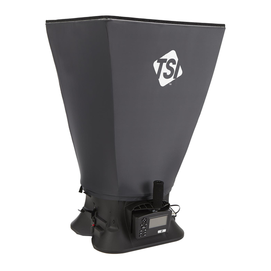
TSI 8380 AccuBalance Air Capture Hood
Model 8715
DP-C
Micromanometer and
ALC
TM
Model 8380 A
B
®
CCU
ALANCE
Modular Air Balancing Tool
Operation and Service Manual
Model 8380 A
B
Model 8715 DP-C
Micromanometer
CCU
ALANCE
ALC
Modular Air Balancing Tool
(shown with standard and optional accessories)
www.netzerotools.com
Advertisement
Table of Contents

Related Manuals for TSI Incorporated 8380 ACCUBALANCE


Summary of Contents for TSI Incorporated 8380 ACCUBALANCE
- Page 1 ENERGY AND COMFORT Ventilation Testing/Balancing TSI 8380 AccuBalance Air Capture Hood Model 8715 DP-C Micromanometer and Model 8380 A ® ALANCE Modular Air Balancing Tool Operation and Service Manual Model 8380 A Model 8715 DP-C Micromanometer ALANCE Modular Air Balancing Tool (shown with standard and optional accessories) www.netzerotools.com...
- Page 2 Seller. This LIMITATION OF WARRANTY AND LIABILITY may not be amended, modified or its terms waived, except by writing signed by an Officer of Seller. Trademarks ® , TSI logo, LogDat-CH, are trademarks of TSI Incorporated. www.netzerotools.com...
-
Page 3: Table Of Contents
www.netzerotools.com CONTENTS About This Manual ........................v Formatting and Typography ....................v Technical Assistance—Help! ....................v Chapter 1. Introduction ......................1 Instrument Description ......................1 Micromanometer ....................... 2 Micromanometer ........................3 Standard Tools ........................4 Pitot Tube .......................... 4 Static Pressure Probe ....................... 4 ®... - Page 4 www.netzerotools.com Calibration Factor (Cf) Selection ..................40 Calibration ........................40 Printing Data Using the Portable Printer ................41 LogDat-CH™ Downloading Software ..................41 Chapter 5. Changing Capture Hoods ..................43 Capture Hood Parts Identification ..................43 Capture Hood Assembly ....................... 43 Alternate Hood Installation ....................
-
Page 5: About This Manual
www.netzerotools.com About This Manual ® This manual explains how to set up, operate and maintain the TSI Model 8715 DP-C Micromanometer and Model 8380 A Air Balancing Tool. Please read it thoroughly before ALANCE using the instrument. Formatting and Typography Step-by-step instructions are numbered in boldface type: 1, 2, 3, etc., set flush-left against the ... -
Page 6: Chapter 1. Introduction
www.netzerotools.com Chapter 1. Introduction The Model 8715 DP-C Micromanometer and 8380 A Air Balancing Tool are ALANCE lightweight and easy-to-use instruments packaged with a variety of accessories for measuring pressure, temperature, humidity, air velocity, and air volume. Features of the micromanometer include: Single-function keys for ease of use ... -
Page 7: Micromanometer
www.netzerotools.com downloading software and RS232 interface cable, neck strap, internal NiMH battery charger, (4) AA NiMH batteries, AC adapter, and NIST traceable certificate. The basic Model 8380 contains all of the Model 8715 components plus 2 ft 2 ft (610 mm 610 mm) air capture hood, frame, base and Swirl-X flow conditioner. - Page 8 www.netzerotools.com ® Figures 3 and 4 show the features of the A Capture Hood. ALANCE Removable Center Handle Backpressure Flap Actuator Switch to pause a reading or to Base Handle initiate backpressure compensation Figure 3: Features of the Model 8380 Base, Side View Backpressure Flap Flow Manifold Mount for Hood...
-
Page 9: Standard Tools
www.netzerotools.com Standard Tools This section gives a brief description of standard tools for the micromanometer. Pitot Tube The pitot tube is primarily used to obtain air velocity, air volume, and velocity pressure measurements within ductwork. An 18 in. (46 cm) pitot tube is included with the Model 8315 or Model 8380 kits. Alternate sizes are available. -
Page 10: Thermoanemometer Probes
www.netzerotools.com Thermoanemometer Probes Thermoanemometer probes can be used to measure air temperature, air velocities or air volume measurements in ductwork as well as lower velocity applications such as face velocity measurements of chemical fume hoods, biological safety cabinets and filtration systems. Four models are available in straight or articulating construction, and with or without a relative humidity sensor. -
Page 11: Chapter 2. Unpacking And Setting Up
Table 1: List of Standard and Optional Components Item Part No. Model 8715 Micromanometer Kit 8715 Model 8380 AccuBalance Capture Hood Kit 8380 Carrying case, Model 8715 1319378 Carrying case, wheeled hood kit, Model 8380 1319379 AA-size NiMH battery, four required... -
Page 12: Preparing The Instrument For Use
www.netzerotools.com Table 2: List of Optional Hood and Frame Kits Item Part No. 1 ft 4 ft (305 mm 1220 mm) fabric hood and frame kit 801200 2 ft 4 ft (610 mm 1220 mm) fabric hood and frame kit 801201 1 ft ... - Page 13 www.netzerotools.com To select the type of batteries you are using: 1. Turn the unit off and locate the battery cover on the back of the micromanometer (see Figure 5). Figure 5: Battery Cover Removal 2. Press down on the compartment cover and slide it down. (The cover slides off.) 3.
-
Page 14: Using The Pressure Ports
www.netzerotools.com 3. Remove the battery holder by pulling up on the bottom (to loosen it) and then remove the battery holder. 4. Remove the old batteries and replace with fresh batteries (alkaline or rechargeable NiMH). Make certain batteries are correctly oriented. 5. -
Page 15: Connecting A Pitot Tube
www.netzerotools.com Connecting a Pitot Tube When the micromanometer is connected to a pitot tube, air velocity or air volume measurements can be taken. The pitot tube is connected to the (+) and (–) pressure ports on the micromanometer using two pieces of tubing of equal length. -
Page 16: Connecting The Static Pressure Port To The Micromanometer
www.netzerotools.com Connecting the Static Pressure Port to the Micromanometer The static pressure port on the static pressure probe will be connected to the (+) port on the micromanometer. The (-) port on the micromanometer will be open to atmosphere (see Figure 9). The Static Pressure probe is used to measure the duct static pressure and features a magnet which holds the probe to the ductwork. -
Page 17: Connecting The Velocity Matrix To The Micromanometer
www.netzerotools.com Connecting the Velocity Matrix to the Micromanometer The positive port (+) is located on the side of the Velocity Matrix that is opposite the handle assembly. The positive port (+) on the Velocity Matrix will be connected to the (+) port on the micromanometer, and the negative port (–) on the Velocity Matrix is connected to the (–) port on the micromanometer. -
Page 18: Connecting The Air Flow Probe To The Micromanometer
www.netzerotools.com Connecting the Air Flow Probe to the Micromanometer When the micromanometer is connected to the Air Flow probe (straight pitot probe), air velocity or air volume measurements can be taken. The Air Flow probe is connected to the (+) and (–) pressure ports on the micromanometer using two pieces of tubing of equal length. -
Page 19: Connecting The Base Temperature Probe, Temperature And Humidity Probe Or Thermoanemometer Probe To The Micromanometer
www.netzerotools.com Connecting the Base Temperature Probe, Temperature and Humidity Probe or Thermoanemometer Probe to the Micromanometer These probes have a “D” shape overmolding on the mini-DIN connector which must align with the connector on the right hand side of the micromanometer (see Figure 13). This will ensure the probe is properly connected and remains so during use. -
Page 20: Retracting The Probe
www.netzerotools.com Retracting the Probe To retract the probe, hold the handle in one hand while gently pulling the probe cable until the smallest antenna section is retracted. C A U T I O N Do not use the instrument or probes near hazardous voltage sources since serious injury could result. -
Page 21: Chapter 3. Getting Started
www.netzerotools.com Chapter 3. Getting Started This section provides information to help you quickly become familiar with the Micromanometer functions. Keypad Functions The keypad lets you enter information, initiate functions, and change values stored in the micromanometer. It will be helpful before operating the micromanometer to understand what each of the keys functions do. -
Page 22: Common Terms
www.netzerotools.com Keypad Function Description Enter ( ) Key Press to accept a menu selection, value or condition. Press to Start or Stop data logging when in Continuous Key mode. READ Key If the Data Logging is set to Manual/Single, pressing the READ key begins a reading, which stops automatically when the reading is done. - Page 23 www.netzerotools.com Term Description The logging interval is the period over which the instrument will average the Log Interval logged sample. For example, if the logging interval is set to 30 minutes, each sample will be the average over the previous 30 minutes. Log Interval is used with Cont-Key/RunAvg and Cont-time/RunAvg logging modes.
-
Page 24: Chapter 4. Menu Setup And Navigation
www.netzerotools.com Chapter 4. Menu Setup and Navigation Menus The menu structure is organized to allow easy MENU navigation and instrument setup utilizing the Pressure Tool Display Setup arrow and keys. To exit a menu or menu Flow Setup item, press the key. - Page 25 www.netzerotools.com Table 3 identifies each Pressure Tool and the units of measure available each. Table 3: Pressure Tool Selection and Display Display Shows Tool Units Available Capture Hood l/s, m /hr, m /s, CFM with flow units Pressure units only Pressure Only in H O, mm H...
-
Page 26: Display Setup
www.netzerotools.com Display Setup Display Setup menu is where you will setup the desired parameters to be displayed on the instrument screen. With a parameter highlighted you can then use the arrow key to have it show up on the instrument screen or select the arrow key to turn off the parameter. -
Page 27: Flow Setup [Pitot Tube, Af Probe (Straight Pitot Tube) Or Thermoanemometer Probe]
www.netzerotools.com Flow Setup [Pitot Tube, AF Probe (straight pitot tube) or Thermoanemometer Probe] Flow Setup mode, there are three types when using a Pitot tube, AF probe or thermoanemometer probe: Round Duct, Rectangle Duct and Duct Area. Use the and keys to scroll through the types and then press the key to accept. -
Page 28: Actual/Standard Setup
www.netzerotools.com Note Press/Kfact allows for calculating flow rate from diffusers or flow stations with pressure taps using the instruments pressure ports and Kfactors. The Kfactors are obtained from the diffuser or flow station manufacturer. For more information, refer to Application Note TSI-114. -
Page 29: Settings
www.netzerotools.com Settings menu is where you can set the general Settings SETTINGS Language English settings. These include Language, Beeper, Select Beeper Disable Units, Time Constant, Contrast, Set Time, Set Select Units Date, Time Format, Date Format, Number Format, Time Constant 1 Second Backlight, Auto Off. -
Page 30: Data Logging
www.netzerotools.com Data Logging Measurements Measurements to be logged to memory are independent of measurements on the display, and must therefore be selected under DATA LOGGING Measurements When set to , measurement will be logged to memory. When set to DISPLAY , measurement will be logged to memory if it is visible on the main running screen. - Page 31 www.netzerotools.com MENU Pressure Tool Display Setup Flow Setup Actual/Std Setup Settings Data Logging DATA LOGGING Bluetooth Functions Measurements Applications LOG MODE/DISPLAY MODE Log Mode/Display Mode Manual/RunAvg Cf Selection Log Settings Calibration Manual/Single Choose Test Test 001 Manual/RunAvg Name Test Auto-Save/RunAvg View Data Cont-Key/RunAvg Delete Data...
- Page 32 www.netzerotools.com Auto-Save/RunAvg Logging mode, the user samples are automatically logged to memory at the end of the Auto-Save/RunAvg sampling period. To start logging, press the key. The Auto-Save/RunAvg mode is recommended when using the optional thermoanemometer probes. MENU Pressure Tool Display Setup Flow Setup Actual/Std Setup...
- Page 33 www.netzerotools.com Cont-key Logging mode, the user starts logging by pressing . The instrument will continue Cont-key SAVE logging until is pressed is pressed again. This mode would be used for long term SAVE data logging. MENU Pressure Tool Display Setup Flow Setup Actual/Std Setup Settings...
- Page 34 www.netzerotools.com Cont-Time/RunAvg Logging mode, the user starts taking readings by pressing . The Cont-Time/RunAvg SAVE instrument will continue taking samples until the time as set in “Test Length” has elapsed or SAVE is pressed. MENU Pressure Tool Display Setup Flow Setup Actual/Std Setup Settings Data Logging...
- Page 35 www.netzerotools.com Choose Test Test IDs consist of a group of Samples that are used to determine statistics (average, minimum, and maximum) of a measurement application. The instrument can store 26,500+ samples and 100 test IDs (one sample can contain multiple measurement parameters such as flow and temperature). Example: Each duct traverse will have its own Test ID consisting of several Samples.
- Page 36 www.netzerotools.com View Data/Choose Test To view stored data, first select the Test ID that contains the data to be recalled. This is accomplished in the menu. Choose Test MENU Pressure Tool Display Setup DATA LOGGING Flow Setup Measurements Actual/Std Setup Log Mode/Display Mode Manual/RunAvg Settings...
- Page 37 www.netzerotools.com View Samples MENU Pressure Tool Display Setup DATA LOGGING Flow Setup Measurements Actual/Std Setup Log Mode/Display Mode Manual/RunAvg Settings Log Settings Data Logging Choose Test Test 001 Bluetooth Functions VIEW DATA Name Test Applications Choose Test Test 022 View Data Cf Selection View Stats Delete Data...
- Page 38 www.netzerotools.com Delete Data Use this menu item to delete all data, delete test or delete a sample. MENU Pressure Tool Display Setup DATA LOGGING Flow Setup Measurements Actual/Std Setup Log Mode/Display Mode Manual/RunAvg Settings Log Settings Data Logging Choose Test Test 022 Bluetooth Functions Name Test...
- Page 39 www.netzerotools.com Delete Test will clear stored data in an individual Test ID selected by the user. MENU Pressure Tool Display Setup DATA LOGGING Flow Setup Measurements Actual/Std Setup Log Mode/Display Mode Manual/RunAvg Settings Log Settings Data Logging Choose Test Test 005 Bluetooth Functions Name Test Applications...
-
Page 40: Bluetooth Functions
www.netzerotools.com % Memory This option displays the memory available. , under , will clear memory and Delete All Delete Data reset the memory available to 100%. DATA LOGGING Measurements Log Mode/Display Mode Manual/RunAvg Log Settings Choose Test Test 001 Name Test View Data Delete Data % Memory... -
Page 41: Applications
www.netzerotools.com PINcode The PINcode is a security key to be entered into the computer if prompted. The factory default PINcode is 0000. Note PINcode must be set to 0000 in order to use 8934 printer. # AutoConnects Specifies how many times the instrument will attempt to reattach to a paired device after the power is turned on. - Page 42 www.netzerotools.com Velocity or ROUND DUCT MEAS volume flow based on Move: 0.3 in Primary 597 ft /min selection in Display Setup 0:00 Sample measurement SAVE? countdown Test 001 Test ID Name Sample 1 and Sample To input round or rectangular duct dimensions, refer to the Flow Setup section of this manual.
-
Page 43: Calibration Factor (Cf) Selection
www.netzerotools.com Calibration Factor (Cf) Selection The correction factor is an offset that can be applied to the velocity measurements when using the AF Probe, Pitot tube and Velocity Matrix or flow when using the Capture Hood. An offset of ±50% (0.500 to 1.500) can be applied to the measurement. -
Page 44: Printing Data Using The Portable Printer
www.netzerotools.com Printing Data Using the Portable Printer To print logged data, first enter the DATALOGGING menu. Then, use the CHOOSE TEST item to select the data to be printed. After the test is selected, use the VIEW STATS VIEW SAMPLES items to select statistics or individual data points to view and print. -
Page 45: Chapter 5. Changing Capture Hoods
www.netzerotools.com Chapter 5. Changing Capture Hoods This chapter identifies the flow hood parts and gives instructions for assembling the flow hood. Capture Hood Parts Identification Figure 15 identifies the major parts of the capture hood, which are described in the following paragraphs. Before using the hood, please familiarize yourself with the various parts. -
Page 46: Alternate Hood Installation
www.netzerotools.com Figure 16: Installing a Support Pole 4. Insert the second support pole into the pole mount on the opposite side of the base. 5. Repeat step 3 for the second support pole. 6. Repeat steps 4 and 5 for the remaining two support poles. Four other hood sizes are available from TSI and can be purchased separately. - Page 47 www.netzerotools.com Figure 17: 1 ft 4 ft (305 mm 1220 mm) hood and frame. The support poles always cross as pairs at the front and back of the fabric hood. For the 1 ft 4 ft (305 mm 1220 mm), the support poles are inserted into the outside ferrule locations.
- Page 48 www.netzerotools.com Figure 18: 2 ft 4 ft (610 mm 1220 mm) hood and frame. The support poles always cross as pairs at the front and back of the fabric hood. For the 2 ft 4 ft (610 mm 1220 mm), the support poles are inserted into the inside ferrule locations.
- Page 49 www.netzerotools.com Figure 19: 1 ft 5 ft (305 mm 1525 mm) hood and frame. The support poles always cross as pairs at the front and back of the fabric hood. For the 1 ft 5 ft (305 mm 1525 mm), the support poles are inserted into the inside ferrule locations.
- Page 50 www.netzerotools.com Figure 20: 3 ft 3 ft (915 mm 915 mm) hood and frame. The support poles always cross as pairs at the front and back of the fabric hood. For the 3 ft 3 ft (915 mm 915 mm), the support poles are inserted into the outside ferrule locations.
-
Page 51: Direct Inflow Measurement Hood For Biological Safety Cabinets
www.netzerotools.com Figure 22: Frame Side Coupler Assembly Each hood is constructed in a trapezoidal shape, sewn together so that one open end forms a round attachment to the base, and the other forms a square or rectangle large enough to fit its matching frame assembly. - Page 52 www.netzerotools.com The direct inflow BSC hood includes (see Figure 24): Fixed frame assembly with four removable flaps Fabric hood Hood support poles Base mounting hardware (threaded insert, washer, and screw) Telescopic pole stand with case to freely hold the capture hood in a vertical position when mounted to a biological safety cabinet or lab hood Figure 24: Direct Inflow Measurement Hood Components To complete the assembly of the BSC hood, follow these seven steps:...
- Page 53 www.netzerotools.com 2. Attach the fabric hood and hood support poles to the frame and base assembly in the same manner as previously described for the other hood sizes. 3. Insert the flaps into the slots from the side of the frame where the fabric hood is attached to the U-channel of the frame (see Figure 26).
- Page 54 www.netzerotools.com 5. Adjust the height and position of the telescopic stand so that the bottom part of the hood frame rests against the cabinet opening, and the capture hood is horizontal to the cabinet (see Figure 28). Figure 28: Adjust Height and Position of Telescopic Stand 6.
- Page 55 www.netzerotools.com 7. Adjust the flaps to cover the opening of the cabinet. Tape the edges of the flaps to the sash and frame of the cabinet to create a tight fit. The unit is now ready to make measurements (see Figure 30). Figure 30: Unit Ready to Make Measurements Chapter 5: Changing Capture Hoods www.netzerotools.com...
-
Page 56: Chapter 6. Flow Measurements Using The Capture Hood
www.netzerotools.com Chapter 6. Flow Measurements Using the Capture Hood There are two methods of making flow measurement using Capture Hood: (1) Capture Hood (non-backpressure compensation). (2) Capture Hood with backpressure compensation. “Appendix A. Back Pressure,” for an explanation of the implications of capture hood-induced back (See pressure on the measured flow.) Supply or return flows can be measured with both methods, and return flow is indicated as a negative... -
Page 57: Running Average Measurements
www.netzerotools.com Running Average Measurements In this mode, the instrument will measure continuously while displaying a running average of flow. Pressing either the READ key on the meter or the red switch on the base will hold the current reading. To restart the running average measurement, press the READ key or the red switch. -
Page 58: Error‖ Display
www.netzerotools.com Note It is important that the capture hood see the same flow for both parts of the backpressure compensated flow measurement. It is best to keep the Capture Hood in place for both measurements, but it is alright to remove and replace the Capture Hood between the two readings. -
Page 59: Chapter 7. Maintenance And Troubleshooting
www.netzerotools.com Chapter 7. Maintenance and Troubleshooting The Model 8380 is designed for long-term field use. If used with reasonable care, it should be able to make precise measurements over a long time period. Some of the components can be cleaned periodically. - Page 60 www.netzerotools.com Table 4 list the symptoms, possible causes, and recommended solutions for common problems encountered with the instrument. If your symptom is not listed, or if none of the solutions solves your problem, please contact the factory. Table 4: Troubleshooting the Instrument Symptom Possible Causes Corrective Action...
-
Page 61: Appendix A. Back Pressure
www.netzerotools.com Appendix A. Back Pressure The quantity of air flowing through a supply diffuser or a return grille is reduced to some extent whenever a capture hood is placed over the flow opening. The amount of flow reduction will vary depending on the combined effects of the diffuser/grille resistance, the capture hood resistance, system pressure and the flow rate. -
Page 62: Appendix B. Traversing A Duct To Determine Average Air Velocity Or Volume
www.netzerotools.com Appendix B. Traversing a Duct to Determine Average Air Velocity or Volume The following techniques can be used to measure air flow inside ducts, using a velocity probe or pitot- static tube. When using a pitot-static tube, the individual velocities must be calculated for each pressure reading and then averaged together. -
Page 63: Traversing A Square Duct
www.netzerotools.com 0.032dia 0.135dia 0.321dia 0.679dia 0.865dia 0.968dia Figure 31: Location of Measuring Points when Traversing a Round Duct using Log-Tchebycheff Method #of Measuring Points Per Diameter Position Relative to Inner Wall 0.032, 0.135, 0.321, 0.679, 0.865, 0.968 0.021, 0.117, 0.184, 0.345, 0.655, 0.816, 0.883, 0.979 0.019, 0.077, 0.153, 0.217, 0.361, 0.639, 0.783, 0.847, 0.923, 0.981 Before taking the measurement, multiply the numbers in the table times the duct diameter to get insertion depth for the probe. - Page 64 www.netzerotools.com 0.926 V 0.712 V 0.500 V 0.288 V 0.074 V 0.061 H 0.235 H 0.437 H 0.563 H 0.765 H 0.939 H Figure 32: Location of Measuring Points for Traversing a Rectangular Duct using Log-Tchebycheff Method For this duct, a 30-36” horizontal dimension requires 6 points (or 6 traverse lines). For this duct, a vertical dimension less than 30”...
-
Page 65: Appendix C. Swirl X Flow Conditioner For Tsi Model 8380 Accu Balance Air Capture Hood
www.netzerotools.com Appendix C. Swirl X Flow Conditioner for TSI ® Model 8380 A Air Capture Hood ALANCE Description The Swirl X Flow Conditioner significantly reduces the negative effects turbulent airflows have on the measurement accuracy of pressure- based capture hoods. The Swirl X Flow Conditioner creates a more uniform flow pattern within the hood and is ideally suited for Swirl or Twist-type supply air diffusers. -
Page 66: Performance Data
www.netzerotools.com Performance Data Performance data obtained in HVAC test laboratory using two high-accuracy flow stations as flow measurement standards. The flow stations were mounted in sealed ductwork upstream of the tested Swirl Diffusers. 8380 Performance Data (Swirl Diffuser on 200mm Dia. Duct) 8380 with Swirl-X 8380 (No Swirl-X) 8380 Allowed Tolerance... -
Page 67: Installation And Usage
www.netzerotools.com Installation and Usage 1. Put the two pieces together and place it in the base as shown below (it will sit on top of the flange of the base). 2. Install the support rods and 2’ x 2’ (610 mm x 610 mm) frame/fabric. 3. -
Page 68: Specifications
www.netzerotools.com ® Models 8715/8380 Specifications Range Statistics ...... min, max, average Differential pressure ... ±15 in. H O (3735 pa); 150 in. Data Storage ....26,500 samples, time and date O maximum safe operating stamped pressure Logging Interval ..user selectable Absolute pressure ..
Need help?
Do you have a question about the 8380 ACCUBALANCE and is the answer not in the manual?
Questions and answers