
Related Manuals for TSI Incorporated 8587A


Summary of Contents for TSI Incorporated 8587A
- Page 1 LASER PHOTOMETER MODEL 8587A OPERATION AND SERVICE MANUAL P/N 1980538, REVISION D JULY 2015...
- Page 3 Introduction Unpacking and Setting Up the Laser Photometer LASER PHOTOMETER Technical Description MODEL 8587A Instrument Operation OPERATION AND SERVICE MANUAL Maintenance and Service Appendixes...
- Page 4 M a n u a l H i s t o r y The following is a history of the Model 8587A Laser Photometer Operation and Service Manual (Part Number 1980538). Revision Date December 2005 April 2008 March 2009 July 2015...
- Page 5 Part Number 1980538 / Revision D / July 2015 Copyright ©TSI Incorporated / 2005-2015 / All rights reserved. Address TSI Incorporated / 500 Cardigan Road / Shoreview, MN 55126 / USA Fax No. 651-490-3824 E-mail Address particle@tsi.com Limitation of Warranty...
- Page 6 If any mal- function is discovered, please contact your nearest sales office or representative, or call TSI’s Customer Service department at 1-800-874-2811 (USA) or (651) 490-2811. Model 8587A Laser Photometer...
- Page 7 Model 8587A Laser Photometer. L a s e r S a f e t y The Model 8587A Laser Photometer is a Class I laser-based instrument. During normal operation, you will not be exposed to laser radiation.
- Page 8 Warns you that the instrument is susceptible to electro-static dissipation (ESD) and ESD protection procedures should be followed to avoid damage. Indicates the connector is connected to earth ground and cabinet ground. viii Model 8587A Laser Photometer...
- Page 9 Advisory labels and identification labels are attached to the outside of the Laser Photometer housing and to the optics on the inside of the instrument. Labels for the Model 8587A Laser Photometer are described below: 1. Serial Number Label (back panel) 2.
- Page 10 (This page intentionally left blank) Model 8587A Laser Photometer...
-
Page 11: Table Of Contents
C o n t e n t s Manual History ................... iv Warranty ...................... v Safety ......................vii Laser Safety ..................vii Description of Safety Labels ..............viii Caution ....................viii Warning ..................... viii Caution or Warning Symbols ............viii Labels .................... - Page 12 Programming Note ................3-9 Flow System ..................3-9 Vacuum Pump ..................3-9 Sensor (Scattering Chamber) ............3-11 Laser Photometer Electronics............3-13 Internal Instrument Components ............3-14 Sensor Assembly ................3-15 Filters ..................... 3-15 Solenoid Valves ................3-15 Pressure Transducer ..............3-16 Electronics Boards .................
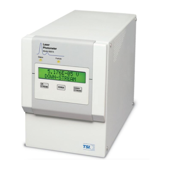
- Page 13 F i g u r e s 1-1 Model 8587A Laser Photometer ............1-2 3-1 Back Panel of the Model 8587A Laser Photometer ......3-3 3-2 Serial Communications Port .............. 3-5 3-3 Flow Schematic Model 8587A Laser Photometer ......3-10 3-4 Sheath Air Flow System ..............
- Page 14 B-17 Set Polling Buffer Size Screen ............B-13 T a b l e s 2-1 Model 8587A Laser Photometer Packing List ........2-1 3-1 Pin Function for Serial Communications Port ........3-5 3-2 Laser Photometer ASCII Command Strings ........3-7 4-1 Example Fit Test Sequence ..............
-
Page 15: Chapter 1 Introduction
Appendix C: Technical Information for Program Development Using USB Communications Describes the software development library found on the Model 8587A Laser Photometer CD-ROM supplied with the instrument. S u b m i t t i n g C o m m e n t s TSI values your comments and suggestions on this manual. - Page 16 (This page intentionally left blank) Model 8587A Laser Photometer...
-
Page 17: Product Description
The sample ports are found at the back of the instrument labeled UPSTREAM and DOWNSTREAM. When the Model 8587A is used for fit testing, the UPSTREAM port is used to sample aerosol from the test chamber. The DOWNSTREAM port is used to sample aerosol from within the mask. -
Page 18: How It Works
Model 8587A Laser Photometer H o w i t W o r k s The Model 8587A Laser Photometer determines aerosol concentration by measuring the level of scattered light produced by aerosol particles as they are passed through a collimated laser beam in the aerosol sensor assembly. -
Page 19: Unpacking
U p t h e L a s e r P h o t o m e t e r Use the information in this chapter to unpack the Model 8587A Laser Photometer and set it up. U n p a c k i n g The following instruments and accessories comprise the Model 8587A Laser Photometer. -
Page 20: Vacuum Pump And Connection
>55 kPa (8 psi). Flow Check The Model 8587A verifies the airflow provided by an external vacuum pump by monitoring the vacuum during upstream and downstream sample modes. This ensures that a critical pressure is maintained during sampling, and in turn, a critical airflow for sampling. -
Page 21: Connecting The Sample Lines
C o n n e c t i n g t h e S a m p l e L i n e s Upstream and Downstream sample lines must be connected at the back of each Laser Photometer. Tube stubs for tubing connections are labeled ... - Page 22 (This page intentionally left blank) Model 8587A Laser Photometer...
-
Page 23: Cabinet
C H A P T E R 3 T e c h n i c a l D e s c r i p t i o n This chapter identifies the basic features of your Model 8587A Laser Photometer and provides general technical information. Detailed... -
Page 24: Status Lights
UPSTREAM or DOWNSTREAM vacuum is less than 30 kPa (4.4 psi). If the FLOW STATUS light is blinking, check for leaks in the vacuum system or a faulty vacuum pump. (continued on next page) Model 8587A Laser Photometer... -
Page 25: Back Panel
BNC connector. The back panel is shown below: Figure 3-1 Back Panel of the Model 8587A Laser Photometer 1 Upstream and downstream sample ports 4. 9-PIN D-type female serial connector 2. Port for external vacuum pump connection 5. -
Page 26: Upstream And Downstream Sample Ports
The BNC electrical connector on the back panel can be used to monitor the analog voltage from the Laser Photometer sensor. The output is 0–10 volts at the minimum detector gain setting. The output has a limited usefulness at lower signal voltages. Resolution is limited to .01 volts. Model 8587A Laser Photometer... -
Page 27: Serial Communications Port
Serial Communications Port A standard nine-pin RS-232 Serial Communications port connector is provided on the back panel of the instrument for control and data acquisition. The connector is a 9-pin, D-type female subminiature type shown. The figure has been rotated 90 degrees clockwise. Pin function is identified in Table 3-1. -
Page 28: Data Acquisition And Instrument Control
USB driver program is installed. A USB Terminal Emulator program is provided on the CD supplied with your Model 8587A. This enables you to, send and receive ASCII characters for external instrument control and data acquisition. Refer to... -
Page 29: Command Strings For Instrument Control And Data Acquisition
Acquisition” later in this chapter for information on instrument control and data acquisition. The Model 8587A is a “client” USB device receiving and transmitting data from a computer. The Model 8587A cannot act as a USB host. Command Strings for Instrument Control and... -
Page 30: Hex Data Retrieval
The voltage data string which is returned after the “K” command is sent represents a continuous average since the last time the voltage was read with the “K” or “D” command, or since the last reset "R" string was sent to the Laser Photometer. Model 8587A Laser Photometer... -
Page 31: Data Averaging
DATA Averaging Each one-tenth of a second, an average of over 100 A/D readings is taken and summed by the Laser Photometer microprocessor. The number of tenth second readings is recorded and at the time the data is polled, the sum of voltage readings is divided by the number of readings since the last reset (“R”, “D”... -
Page 32: Flow Schematic Model 8587A Laser Photometer
The vacuum pump is connected to the port labeled VACUUM on the back panel. Refer to the Chapter 4, “Instrument Operation” for more information on pump requirements. Figure 3-3 Flow Schematic Model 8587A Laser Photometer 3-10 Model 8587A Laser Photometer... -
Page 33: Sensor (Scattering Chamber)
S e n s o r ( S c a t t e r i n g C h a m b e r ) The Laser Photometer aerosol sensor (scattering chamber) is depicted schematically in Figure 3-3. Relative aerosol concentration measurements outside and inside a mask, or upstream and downstream of the filter are made here. -
Page 34: Sheath Air Flow System
Figure 3-4 Sheath Air Flow System 3-12 Model 8587A Laser Photometer... -
Page 35: Laser Photometer Electronics
L a s e r P h o t o m e t e r E l e c t r o n i c s The function of the photometer electronics is to measure and display the photodetector voltage. The photometer electronics incorporates a 12 bit successive approximation A/D (Analog to Digital) converter combined with a 6 decade gain amplification circuit to measure photodetector voltages. -
Page 36: Internal Instrument Components
I n t e r n a l I n s t r u m e n t C o m p o n e n t s The internal components are shown in Figure 3-5 and are described on the following pages. Figure 3-5 General Location of Internal Components of the Model 8587A Laser Photometer 1. Sensor assembly 6. Flow valve 2. Sheath filter 7. -
Page 37: Sensor Assembly
Sensor Assembly The sensor assembly consists of the aluminum block scattering chamber, laser mount and laser driver board, photodiode detector and detector electronics PCB and sampling inlet with unique sheath air design using a sheath filter. Aerosol is drawn into the sensor assembly at nominally 2 L/min (.07 cfm). in sampling modes, UPSTREAM and DOWNSTREAM, and at higher flow >12 L/min (0.43 cfm) in the PURGE mode. -
Page 38: Pressure Transducer
2.00 0.071 Electronics Boards Four electronics boards are used in the Model 8587A. The boards include Main PC board, laser board, detector board, communication connector board. The main board has the microprocessor and performs all intelligent functionality, controlling valves and reading inputs and performing basic calculations. -
Page 39: Turning On The Laser Photometer
I n s t r u m e n t O p e r a t i o n This chapter describes the basic operation of the Model 8587A Laser Photometer and provides information on the use of controls, indicators, and connectors found on the front and back panels. -
Page 40: Vacuum Pump Requirements
During PURGE mode the free airflow must be between 12 and 30 L/min (0.42 and 1.05 cfm). For example, a pump supporting three Model 8587A instruments should ideally provide >6 L/min (0.21 cfm) for upstream and downstream sample modes and 45 to 90 L/min (1.6 to 3.2 cfm) for purge... -
Page 41: Connecting Sample Lines
It is recommended that the tube lengths not exceed 3 meters (10 ft). F l o w S e t u p The Model 8587A laser photometer is factory adjusted to draw in air at a rate of approximately 2 L/min (.07 cfm) during UPSTREAM and DOWNSTREAM sampling modes. -
Page 42: Performing Fit Tests
P e r f o r m i n g F i t T e s t s Respirator fit testing using TSI’s Model 8587A Photometer can be accomplished using these suggestions. Test Control The Laser Photometer has been designed specifically for use with an external control and data acquisition program through its RS-232 or USB communications port. -
Page 43: Fit Test Under Computer Control
5. Press the DOWNSTEAM keypad to switch to the downstream sample mode. Wait for the voltage to stabilize (20 seconds). Over a minute interval, record 10 data points. Fit factor is often based on the worst- case, e.g., highest aerosol level, include the highest voltage seen. This value is used to determine worst-case Fit Factor. -
Page 44: Filter Testing Aerosol
TSI uses the same aerosol sensor in the Model 8587A Laser Photometer as is used in its popular Model 8130 Filter Tester. Aerosols of Dioctyl-Phalate (DOP), Emery Oil, or Olive oil or a mean diameter of 0.2 to 0.3 microns and geometric standard deviation (GSD) of... -
Page 45: Performing A Filter Test
P e r f o r m i n g a F i l t e r T e s t Performing a filter test is very similar to performing fit testing described in the previous section. The UPSTREAM sample is drawn from the filter holder, providing the challenge aerosol. - Page 46 (This page intentionally left blank) Model 8587A Laser Photometer...
-
Page 47: Filter Replacement
The filters are shown and identified in Figure 3-5. A filter replacement schedule is presented below. A filter replacement kit, part number 1083636, can be ordered from TSI TSI Incorporated 500 Cardigan Road Shoreview, Minnesota 55126, USA... -
Page 48: Filter Replacement Instructions
Periodically check the reading during the purge mode operation. If the zero voltage is approaching 8 10 volts, the Laser Photometer may need to be returned to the factory for service. This will depend somewhat on the application requirements. Model 8587A Laser Photometer... -
Page 49: Changing Sample Flow
C h a n g i n g S a m p l e F l o w The Laser Photometer sample flow is set at the factory for a flow of 2 L/min (0.07 cfm) by adjusting the fine flow control needle valve placed in parallel with an orifice. -
Page 50: Technical Contacts
If you have any difficulty installing the Laser Photometer, or if you have technical or application questions about this instrument, contact an applications engineer at TSI Incorporated, (651) 490-2811 or email particle@tsi.com. If the Laser Photometer fails, or if you are returning it for service, visit our website at http://service.tsi.com... -
Page 51: Returning The Laser Photometer For Service
R e t u r n i n g t h e L a s e r P h o t o m e t e r f o r S e r v i c e Visit our website at http://rma.tsi.com or call TSI Customer Service at 1- 800-874-2811 (USA) or (651) 490-2811 for specific return instructions. - Page 52 (This page intentionally left blank) Model 8587A Laser Photometer...
-
Page 53: Model 8587A Laser Photometer Specifications
A P P E N D I X A S p e c i f i c a t i o n s Table A-1 contains the operating specifications for the Model 8587A Laser Photometer These specifications are subject to change without notice. -
Page 54: Appendix A Specifications
In order to use one vacuum pump simultaneously with two or more 8587A photometers, it is necessary to coordinate (synchronize) the sampling and purge functions. -
Page 55: Accessing The Laser Photometer Cd
A c c e s s i n g t h e L a s e r P h o t o m e t e r C D With the computer on and Windows running, insert the Model 8587A CD- ROM in your CD drive. -
Page 56: Usb Terminal Emulator Program
U S B T e r m i n a l E m u l a t o r P r o g r a m This section outlines the use of the USB Terminal Emulator program found on the CD-ROM supplied with the Model 8587A Laser Photometer. The USB Terminal Emulator program enables remote control of the photometer functions and access to instrument data through a USB cable connected to a computer via the USB port (Figure 3-1). -
Page 57: Tsi Usb Device Driver Installshield Wizard Screen
2. To install the USB terminal Emulator program, click “Install USB Terminal Emulator” with your mouse. The InstallShield Wizard will appear as shown in Figure B-2. Note: Installing the USB Terminal Emulator will automatically cause the USB drivers to be installed first. It is not necessary to install the USB driver separately (by clicking “Install USB Driver”) unless you want to install the driver without also installing the terminal emulator. -
Page 58: License Agreement Screen
3. Continue by pressing Next. Figure B-3 License Agreement Screen 4. Accept the license agreement and press Next. Figure B-4 Choose Destination Location Screen Model 8587A Laser Photometer... -
Page 59: Begin Installation Screen
5. Click Next to install the program into the folder shown. To specify a different location click Change. Figure B-5 Begin Installation Screen 6. Click Install to begin the install process. Figure B-6 Setup Status Screen Laser Photometer CD... -
Page 60: Installshield Wizard Complete Screen
USB Terminal Emulator program. Figure B-8 TSI USB Terminal Shortcut Icon “Connecting To connect the USB, follow the instructions in the next section USB for the First Time.” Model 8587A Laser Photometer... -
Page 61: Connecting Usb For The First Time
CD-ROM included with your instrument must be installed. This process was described in the sections above. In addition, the computer needs to add the Model 8587A Laser Photometer to a list of recognized devices. Steps for adding the Laser Photometer as a new device are described below. -
Page 62: Hardware Wizard Installing Software
7. The unsigned driver warning will be displayed. Select the Continue Anyway button to proceed with the installation. Figure B-11 Unsigned Driver Warning Screen 8. The “Please Wait…” dialog will display until the process is completed. Model 8587A Laser Photometer... -
Page 63: Please Wait While Wizard Installs Software Screen
Figure B-12 Please Wait While Wizard Installs Software Screen 9. Select the Finish button from the screen below. Figure B-13 Completing the Found New Hardware Wizard Screen Laser Photometer CD... -
Page 64: Installation Issues That May Arise
1. Tsiusb Driver installation file: TSIUSB.inf—This file is copied to: c:\Windows\inf folder. 2. Tsiusb driver file TSIUSB.sys—This file is copied to: 7C:\Windows\system32\drivers folder. 3. Tsiusbapi dynamic link library file TsiUsbApi.dll—This file is copied to: C:\Windows\system32 folder. B-10 Model 8587A Laser Photometer... -
Page 65: Starting The Program
Starting the Program The USB Terminal Emulator program provides an icon on the computer desktop which can be used to access the program. If the icon is removed, access the program by selecting Start on the lower left of the computer screen. Then select Programs | TSI | TerminalUSB. -
Page 66: Sending Commands
To save the text in the Operator Input panel, select the File menu and choose Save Input. To save the text in the Instrument Output panel, select File | Save Output. Figure B-15 Saving Input and Output B-12 Model 8587A Laser Photometer... -
Page 67: Setting Timeouts
Setting Timeouts To set the timeout periods for communications with a device, a connection must first be established with a device. Once the connection has been established, select the Device menu, and then choose Timeout. A dialog box will appear, and the desired timeout period can be entered into the text box. - Page 68 (This page intentionally left blank) B-14 Model 8587A Laser Photometer...
-
Page 69: Locating The Header File
U S B C o m m u n i c a t i o n s This appendix concerns the software development library found on the Model 8587A Laser Photometer CD-ROM supplied with the instrument. The purpose of the library is to facilitate user-developed Microsoft Windows software applications that communicate with TSI USB (Universal Serial Bus) devices including the Model 8587A Laser Photometer. -
Page 70: Locating The Dynamic Link Library File
These values are the DWORD return value of the command (the Win32 error code) and the Status value of the device command (the USB Command Status). Model 8587A Laser Photometer... -
Page 71: Troubleshooting Win32 Errors
A successful completion of a command sent to the device will have the following return values: The DWORD win32 Error Code of ERROR_SUCCESS, or 0x0000 The USB command status value of 0x0000, or USB_OK as defined in the TsiUsbApi.h file. For successful operation, ALWAYS pay attention to the win32 return value and the USB command status returned from the device (when this value is present). -
Page 72: Usb Command Status Errors
It is best to open and close the device often rather than open the device once and close the device once, over a long period. The device USB connection can be unplugged during device operation. The Driver and DLL will handle this. Model 8587A Laser Photometer... -
Page 73: Connecting To The Attached Device
W i n d o w s R e g i s t r y S e t t i n g s The TsiUsb Device driver and DLL make use of the Windows registry for a few variable values. These values are maintained within the following registry key: [HKEY_LOCAL_MACHINE\SYSTEM\CurrentControlSet\Services\ TSIUSB\Parameters]... -
Page 74: Deviceopen
BOOLEAN transferred to the device. This value should be set to TRUE when opening a connection to a Model 8587A Laser Photometer. Return value: This method returns a handle to the open device. A successful DeviceOpen returns a handle value that is not equal to INVALID_HANDLE_VALUE (0xFFFF). -
Page 75: Communicating With The Attached Device
C o m m u n i c a t i n g w i t h t h e A t t a c h e d D e v i c e TsiUsbTerminalTransmit The TsiUsbTerminalTransmit() method writes data to the device. DWORD TsiUsbTerminalTransmit(IN HANDLE hDevice, IN LPVOID pXmitBuff, IN DWORD xmitBuffSize,... -
Page 76: Tsiusbterminalreceive
The TsiUsbTerminalReceive() methodreads data from the device. DWORD TsiUsbTerminalReceive(IN HANDLE hDevice, IN OUT LPVOID pRecvBuff, IN DWORD recvBuffSize, IN OUT LPWORD pTransID, IN OUT LPWORD pLevelID, IN OUT PULONG pStatus, IN OUT LPDWORD lpNumberOfBytesRead, IN WORD wEndpoint = TSI_USB_TERMINAL_READ_EP); Model 8587A Laser Photometer... - Page 77 Parameter Description Type The handle to the connected device hDevice HANDLE returned from DeviceOpen(). A pointer to a buffer for receiving the data pRecvBuff LPVOID or void* read from the device. The size of the buffer for receiving data recvBuffSize DWORD or Unsigned long read from the device.
-
Page 78: Retrieving Error Strings
Handle returned from DeviceOpen(). HANDLE ulStatus The status value returned from the device. ULONG or an unsigned long The returned string describing the device pStatusString LPCTSTR status error that occurred. The return value is void. C-10 Model 8587A Laser Photometer... -
Page 79: Closing The Connection
TsiUsbGetWin32String The TsiUsbGetWin32String() method returns a win32 string that describes the error code of the Win32 error that is passed in. VOID TsiUsbGetWin32String (IN HANDLE hDevice , IN DWORD dwWin32Err, IN OUT LPCTSTR pWin32ErrStr); Parameter Description Type hDevice Handle returned from DeviceOpen(). HANDLE dwWin32Err The error code returned from the DLL. - Page 80 (This page intentionally left blank) C-12 Model 8587A Laser Photometer...
- Page 81 I n d e x error_dev_not_exist, 8-3 ListDevices(), 8-4, 8-5 error_gen_failure, 8-3 locating header file, 8-1 about this manual, xv error_invalid_handle, 8-3 AC power, 2-1 M–N error_invalid_parameter, 8-3 advisory label, ix error_io_device, 8-3 maintenance, 5-1 aerosol concentration, 1-2 error_operation_aborted, 8-3 manual history, iv analog output BNC connector, 3-4 applying power, 2-1...
- Page 82 USB communications, 8-1 TSI USB terminal shortcut icon, 7-6 tsiusbapi, 8-2 TSIUSBApi.dll, 8-2 tsiusbapi.h, 8-2 TSIUSBApi.h, 8-1 TSIUSBApi.lib, 8-2 TsiUsbGetStatusString, 8-10 TsiUsbGetWin32String(), 8-3 TsiUsbTerminalReceive, 8-8 TsiUsbTerminalTransmit, 8-7 turning on laser photometer, 4-1 Index-2 Model 8587A Laser Photometer...
-
Page 83: Reader's Comments Sheet
Please help us improve our manuals by completing and returning this questionnaire to the address listed in the “About This Manual” section. Feel free to attach a separate sheet of comments. Manual Title Model 8587A Laser Photometer P/N 1980538 1. Was the manual easy to understand and use? - Page 85 TSI Incorporated – Visit our website www.tsi.com for more information. Tel: +1 800 874 2811 India Tel: +91 80 67877200 Tel: +44 149 4 459200 China Tel: +86 10 8219 7688 France Tel: +33 1 41 19 21 99 Singapore...
Need help?
Do you have a question about the 8587A and is the answer not in the manual?
Questions and answers