
Related Manuals for TSI Incorporated DUSTTRAK DRX 8533


Summary of Contents for TSI Incorporated DUSTTRAK DRX 8533
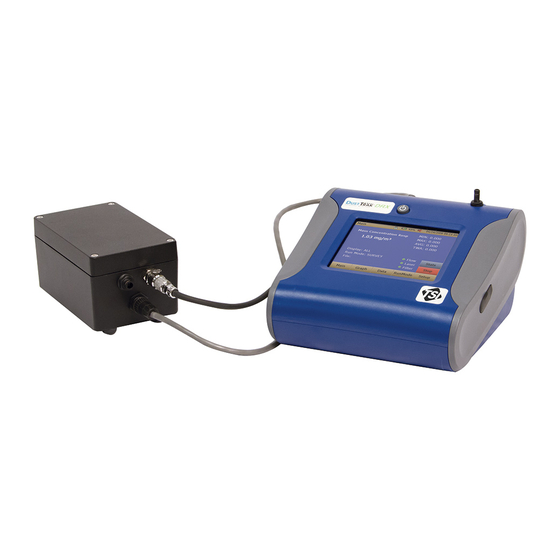
- Page 1 DUSTTRAK™ DRX AEROSOL MONITOR MODEL 8533/8534/8533EP OPERATION AND SERVICE MANUAL P/N 6001898, REVISION L DECEMBER 2014 DustTrak DRX 8533 Desktop and 8534 Handheld DustTrak DRX 8533EP Monitor...
- Page 3 Copyright © TSI Incorporated / 2008–2014 / All rights reserved. Address TSI Incorporated / 500 Cardigan Road / Shoreview, MN 55126 / USA Fax No. (651) 490-3824 LIMITATION OF WARRANTY AND LIABILITY (effective April 2014) (For country-specific terms and conditions outside of the USA, please visit www.tsi.com.)
- Page 4 INJURIES, OR DAMAGES CONCERNING THE GOODS (INCLUDING CLAIMS BASED ON CONTRACT, NEGLIGENCE, TORT, STRICT LIABILITY OR OTHERWISE) SHALL BE THE RETURN OF GOODS TO SELLER AND THE REFUND OF THE PURCHASE PRICE, OR, AT THE OPTION OF SELLER, THE REPAIR OR REPLACEMENT OF THE GOODS.
-
Page 5: Table Of Contents
CONTENTS SAFETY INFORMATION ................V Laser Safety ....................v Labels ......................vi Description of Caution/Warning Symbols ........... vii Caution ....................vii Warning ....................vii Caution and Warning Symbols ..............vii Reusing and Recycling ................vii CHAPTER 1 UNPACKING AND PARTS IDENTIFICATION ......1 Unpacking the DustTrak DRX Aerosol Monitor .......... - Page 6 Taking Mass Concentration Measurements ..........41 Screen Regions .................. 42 Stats ....................43 Graphing ..................... 45 Viewing Data ....................47 Title Bar ..................... 48 CHAPTER 4 MAINTENANCE ..............49 Maintenance Schedule ................49 Zeroing Instrument ..................50 Cleaning the Inlet ..................50 Cleaning 2.5 µm Calibration Impactor ............
-
Page 7: Safety Information
Safety Information I M P O R T A N T There are no user serviceable parts inside the instrument. Refer all repair and maintenance to a qualified factory-authorized technician. All maintenance and repair information in this manual is included for use by a qualified factory-authorized technician. -
Page 8: Labels
Labels Advisory labels and identification labels are attached to the instrument. 1. Serial Number Label (bottom) 2. Laser Radiation Label DANGER! (internal) VISIBLE LASER RADIATION WHEN OPEN. AVOID DIRECT EXPOSURE TO BEAM WARNING: NO USER SERVICABLE PARTS INSIDE. REFER SERVICING TO QUALIFIED PERSONNEL 3. -
Page 9: Description Of Caution/Warning Symbols
Indicates the connector is connected to earth ground and cabinet ground. Reusing and Recycling As part of TSI Incorporated’s effort to have a minimal negative impact on the communities in which its products are manufactured and used: Do not dispose of used batteries in the trash. - Page 10 (This page intentionally left blank) viii...
-
Page 11: Chapter 1 Unpacking And Parts Identification
Chapter 1 Unpacking and Parts Identification Carefully unpack the Model 8533/34 DustTrak DRX Aerosol Monitor from the shipping container. Use the tables and illustrations below to make certain that there are no missing components. Contact TSI immediately if anything is missing or damaged. - Page 12 Part Item Number Description 800663 Zero Filter 801680 6600 mAH Lithium Ion Rechargeable Battery (Desktop) 801681 Rechargeable lithium ion battery (Handheld) 1303740 USB cable 801652 Analog/alarm output cable (Desktop models only) 6001898 Operation and Service Manual Calibration Certificate Chapter 1...
- Page 13 Part Item Number Description 801688 Conductive Tubing 801668 Filter removal tool (Spanner Driver) 801673 Spare Internal Filter Elements Desktop Model Only 37-mm filter includes: Filter body top Filter body bottom Mesh Screen Comes with 37-mm cartridge opening tool. 801666 Spare Internal Filters Handheld Model Only...
- Page 14 Part Item Number Description Power Supply – 801692 Desktop 801694 Power Supply - Handheld Stylus When shipped, one stylus will be in the accessory bag, the second stylus is attached to instrument. 3012094 Screwdriver, dual ended. (For Handheld Models only) 801674 Impactor Oil 801698...
- Page 15 Part Item Number Description 801797 External Pump Power Cable (to DustTrak monitor) for 8533EP only 801798 External Pump Flow Tube (to DustTrak monitor) for 8533EP only Exhaust Adapter, DustTrak monitor for 8533EP only Unpacking and Parts Identification...
-
Page 16: Optional Accessories
Optional Accessories The following photos and table list optional accessories. If you ordered optional accessories, make certain they have been received and are in working order. Part Accessories Number Description 801675 External Pump Kit for 8533EP only 801795 DustTrak II/DRX External Pump Service Kit for 8533EP only. -
Page 17: Parts Identification For The Dusttrak Drx Desktop Aerosol Monitor Model 8533
Parts Identification for the DustTrak DRX Desktop Aerosol Monitor Model 8533 Stylus Inlet On/Off Touchscreen Analog/Alarm Power Output USB Host USB Device Ethernet Zero Module Connector Battery Access Filter Access Figure 1-1: Features on Desktop Model Unpacking and Parts Identification... -
Page 18: Parts Identification For The Dusttrak Ii Desktop Aerosol Monitor Model 8533Ep
Parts Identification for the DustTrak II Desktop Aerosol Monitor Model 8533EP External Pump External Pump Power Connection Flow Tubing Exhaust Adapter External Pump External Pump Module (8533EP only) Pump Pump Suction End Pump Exhaust End User Replaceable HEPA Filters Pump Power Connection Figure 1-2: Features on Desktop Model 8533EP Chapter 1... -
Page 19: Parts Identification For The Dusttrak Drx Handheld Aerosol Monitor Model 8534
Parts Identification for the DustTrak DRX Handheld Aerosol Monitor Model 8534 Inlet On/Off Touchscreen Stylus Port Cover Power USB Host USB Device Filter Access Battery Access (Screw Lockdown) Figure 1-3: Features on Handheld Model Unpacking and Parts Identification... - Page 20 (This page intentionally left blank) Chapter 1...
-
Page 21: Chapter 2 Setting Up
Chapter 2 Setting Up Supplying Power to the DustTrak DRX Aerosol Monitor The Model 8533 and 8534 DustTrak DRX Aerosol Monitor must be powered by either batteries or using the external AC adapter. W A R N I N G The instrument has been design to be used with batteries supplied by TSI. -
Page 22: Connecting The External Pump To Dusttrak Model 8533Ep
Figure 2-2: Batteries into Handheld Unit Connecting the External Pump to DustTrak Model 8533EP The Model 8533EP is a Desktop DustTrak monitor with an external pump. This DustTrak monitor has no internal pump and will not work with any other external pump other than the one provided by TSI (p/n 801675). - Page 23 Likewise, plug one end of the power connector to the pump module as shown above. Turn the power connector until it clicks and locks in place. This prevents the connector from disconnecting due to vibration or movement. Connect the exhaust adapter to the exhaust of the DustTrak monitor (see Figure 2-4).
-
Page 24: Using The Ac Adapter To Run Instrument
Notes The power connector and the flow quick connect “click” when securely connected. The power connector must be rotated clockwise past the locking pin. Do not hot-plug the External Pump Module when the DustTrak monitor is turned ON. Always connect the External Pump module first and then turn the DustTrak monitor ON. -
Page 25: Instrument Setup
Figure 2-6: Putting on Inlet Cap Instrument Setup The DustTrak DRX monitor can be connected to a computer to download data and upload sampling programs. Connecting to the Computer ® ® Connect the USB host port of a Microsoft Windows -based computer to the USB device port on the side of the DustTrak monitor. -
Page 26: Connecting Analog/Alarm Output
TrakPro software contains a comprehensive installation guide. TSI recommends printing out this guide prior to starting the TrakPro software installation on your computer, so it may be consulted during the installation. The TrakPro Software manual is located in the “Help” file in TrakPro software. There is no separately printed TrakPro Data Analysis software manual. -
Page 27: Wiring The Alarm
Wiring the Alarm System specifications: Maximum voltage: 15 VDC (DO NOT USE AC POWER) Maximum current: 1 Amp Correct polarity must be observed (see pin-outs above) The alarm switch, located inside the DustTrak monitor must be located on the ground side of the alarm system. - Page 28 (page intentionally left blank) Chapter 2...
-
Page 29: Chapter 3 Operation
Chapter 3 Operation Getting Started The START UP screen is displayed initially when the instrument is turned on, following the initial TSI logo splash screen. Using a stylus or fingertip, touch the “buttons” on the screen to activate different menus. For Model DustTrak 8533EP only W A R N I N G Always setup and operate the DustTrak monitor with External... - Page 30 Communication errors take place under four different scenarios as follows: When the unit is idle and is not connected to the External Pump Module, a warning displays on the Main screen. Note “No Pump is Connected” is a sticky error. Even after the warning message, if the External Pump Module is connected to the DustTrak, the error will not disappear until the screen is refreshed.
- Page 31 If the pump is not connected while attempting to perform a Zero Cal, an error appears on the Setup screen. If the pump is not connected while attempting to perform a Flow Cal, an error appears on the Setup screen. Operation...
-
Page 32: Setup Menu
Setup Menu Pressing Setup activates the Setup Menu touchscreen buttons along the left edge of the screen. Setup is not accessible when the instrument is sampling. The main screen of the Setup screen displays the following information: Serial Number The instruments serial number. Model Number The instruments model number. -
Page 33: Zero Cal
Zero Cal Run Zero Cal the first time the instrument is used and repeat prior to every use. Zero Cal requires that the zero filter be attached prior to running. Zero Cal must also be performed if the unit is reading negative concentrations. It is not possible for the DustTrak monitor to read negative concentrations. -
Page 34: Flow Cal
Flow Cal Run Flow Cal to change the flow set point. The flow set point is factory set to 3 L/min total flow. 2 L/min of the total flow is measured aerosol flow. 1 L/min of total flow is split off, filtered, and used for sheath flow. There is an internal P flowmeter in the DustTrak DRX instrument that controls flow rate to ±5% if factory setpoint. -
Page 35: User Cal
User Cal User Cal allows you to store and use 10 different calibration factors. In addition, there are two factory defaults, one is the “Ambient Cal” and the other is the “Factory Cal”. The “Ambient Cal” is appropriate for outdoor ambient dust or fugitive dust monitoring. - Page 36 Name User can rename calibration to a description name. Photometric Changes the factory calibration of particle signal, based on Arizona Road Dust, to actual aerosol being measured. See below for sets to set this calibration. Size Corr Changes the factory calibration of the particle distribution, based on Arizona Road Dust, to actual aerosol being measured.
- Page 37 Press the Custom Cal button. Follow the on screen steps to determine the size Corr. The PM impactor is required for this step. Save the calculated value. Operation...
- Page 38 Taking a Gravimetric Sample Using the DustTrak Monitor When sampling with the DustTrak monitor, you can simultaneously take a gravimetric sample either for custom calibration of the DustTrak monitor or for collecting the sample on to the gravimetric filter downstream of the DustTrak monitor without a need for additional gravimetric sampling pump and filter assembly.
- Page 39 filter post weight. Conduct a post-flow calibration with the same sample media done with the pre-flow calibration and determine if these flow calibrations are within ±5% of each other. If they are, use the following to calculate the actual flow rate for the DustTrak monitor. The laboratory will need the following information to calculate mass concentration in mg/m ...
- Page 40 The DustTrak monitor’s custom calibration factor is assigned the value of 1.00 for the factory calibration to standard ISO test dust. This procedure describes how to determine the calibration factor for a specific aerosol. Using the value of 1.00 will always revert back to the factory calibration. To determine a new calibration factor you need some way of accurately measuring the concentration of aerosol, hereafter referred to as the reference instrument.
-
Page 41: Alarm
10. Select Photometric from the User Cal drop down selection and enter the NewCal factor using the onscreen controls. Alarm Alarm allows you to set alarm levels on any of the 5 mass channels PM , RESP, PM and Total. However, the alarm functioning is determined by the logging interval. - Page 42 Note The Alarm is dependent on the logging interval. For the DustTrak to alarm as soon as the Alarm Setpoint is exceeded, the logging interval must be set as low as possible (i.e., 1 second or 2 seconds). If a long test duration does not permit setting such a short logging interval, use the STEL alarm instead.
- Page 43 STEL 1 [On, Off] When the STEL alarm is turned on, STEL data will be collected when Alarm1 level is surpassed. STEL alarm can only be linked to one mass channel at a time. STEL selection is available on the 8533 desktop model only.
-
Page 44: Analog
STEL Alarm STEL stands for Short Term Exposure Limit. When a STEL alarm is selected, the instrument will inspect the data on a second by second basis, independent from the selected logging interval. If the mass exceeds the STEL limit, a STEL even triggers and the following actions will be taken. STEL indicator The STEL indicator will show Red on the main screen. -
Page 45: Settings
Analog setup screen sets the parameters that will drive the analog out port. Applies to the 8533 Desktop model only. Analog out [On, Off] Turns analog out port on. Size Fraction Selects the size channel that will drive the analog out. Output Setting [V, mA] Select between 0 to 5 V and 4 to 20 mA. - Page 46 Background Switches between blue and white backgrounds. Touch Cal Calibrates the touch cal screen. USB PORT IP Address: USB IP is the address assigned to the instrument by the NDIS driver. It is shown but cannot be changed. Ethernet Port IP parameters: (Model 8533 Desktop only.) IP method can be set to static or dynamic.
-
Page 47: Run Mode
Language Switches between display languages. After changing the display language, reboot the instrument. Run Mode The RunMode tab brings up sampling mode options. Sampling mode options include Survey Mode, Manual Log, and Log Mode 1-5. Survey Survey Mode runs a real time, continuous active sample, but does not log data. -
Page 48: Survey Mode
Survey Mode Time Constant Time Constant can be set from 1 to 60 seconds. This will control the update rate of the main screen. It is the rolling average of data displayed on the main screen and is not linked to logged data in either Manual or Program Log modes. -
Page 49: Manual Mode
Manual Mode Log Interval The log interval can be set from 1 second to 60 minutes. It is the amount of time between logged data points. Test Length Test length can be set from 1 minute to the limit of the data storage. -
Page 50: Log Mode (1-5)
Log Mode (1–5) Log Name Log Name, brings up a virtual keypad to name the Logged Data file. Start Date Start Date, select the date the test will start. Start Time Start Time, select the time the test will start. Log Interval The log interval can be set from 1 second to 60 minutes. -
Page 51: Taking Mass Concentration Measurements
Taking Mass Concentration Measurements Measurements are started and controlled from the main screen. Prior to starting a measurement the instrument should be zeroed from the Setup screen and the run mode should be configured and selected from the RunMode screen. When the instrument is on, but not taking any mass measurements the start button will be green and instruments pump will not be running. -
Page 52: Screen Regions
Connect the External Pump Module to the DustTrak monitor and then try again. TSI recommends powering down the DustTrak monitor before connecting the External Pump Module to the DustTrak monitor. Connect the power cable and the flow tubing between the DustTrak monitor and the External pump module, as applicable. -
Page 53: Stats
Error Indicator Region Shows the current stats of the instrument Flow: Status of the flow control Laser: Status of the Laser Filter: Status of the Filter Chapter 5, "Troubleshooting," to resolve any of these error conditions. Stats The Stats button shows the statistics of the highlighted channel. To use the stats feature, first select the channel of interest so it is highlighted in large font on the left of the screen. - Page 54 Next, press the Stats button to show the statistics for the highlighted size channel. Chapter 3...
-
Page 55: Graphing
Graphing During sampling, pressing the Graph button displays current readings in graphical form. During Survey Mode, five (5) minutes of running real-time data is displayed graphically. During Logging Mode, the entire log test time is displayed on the graph. Data Region (live area) Data Label... - Page 56 Data Label Pressing the data label will toggle between PM , PM Resp, PM and Total size segregated mass fractions. Data Region Pressing the data region will bring up a dialog to show TWA or Average lines. TWA: Will show a secondary line on the graph showing the time weighted average of the data.
-
Page 57: Viewing Data
Viewing Data The Data button opens a list of data files for viewing. Select File Press the arrows on the right side of the screen to scroll up or down to the data file to be viewed. Data Statistics Statistics on the selected file File Name Size Channel Sample Average... -
Page 58: Title Bar
Title Bar The Title Bar shows common instrument information. Date Time Battery Status Current Screen Instrument Lock Current Screen Title of the current screen that is being displayed. Instrument Lock Icon shows if the instrument touchscreen is in a unlocked or locked condition. Unlocked: Locked: To lock the touchscreen controls, touch the “lock”... -
Page 59: Chapter 4 Maintenance
Chapter 4 Maintenance The DustTrak DRX aerosol monitor can be maintained in the field using the instructions below. Additionally, TSI recommends that you return your DustTrak DRX monitor to the factory for annual calibration. For a reasonable fee, we will quickly clean and calibrate the unit and return it to you in “as new” working condition, along with a Certificate of Calibration. -
Page 60: Zeroing Instrument
The DustTrak monitor keeps track of the accumulated amount of aerosol drawn through it since its last cleaning. When the internal filter replacement is due, the filter error indicator will turn from green to red. TSI recommends you perform a zero check prior to each use for the DustTrak monitor and certainly before running any extended tests, and after the instrument experiences a significant environmental change. -
Page 61: Cleaning 2.5 Μm Calibration Impactor
Clean the inlet port. Use a cotton swab to clean the outside of the inlet port. The swabs can be dampened with water or a light solvent (e.g., isopropanol). Clean the inside of the sample tube by using a small brush, along with a light solvent. -
Page 62: Replacing The Internal Filters
Screw (hand-tighten) impactor back together. Replacing the Internal Filters Replace the internal filters based on the schedule in Table 4–1 or when the filter indicator on the main screen changes to red. Turn the instrument off. Remove old filters from the instrument. Handheld Model Use the enclosed filter removal tool (PN 801668) tool to unscrew the two filter caps located on the bottom of the instrument. - Page 63 Pull out single cylindrical filter from filter well. If filter well is visibly dirty, blow out with compressed air. Figure 4-6: Pull out Single Cylindrical Filter from Filter Well (Desktop Model) Put a new filer (P/N 801673) back into filter well and screw filter cap back into place.
- Page 64 Remove 37-mm filter cassette by pulling downward and outward. Figure 4-8: Remove 37-mm Filter Cassette Open filter cassette using enclosed tool PN 7001303. Figure 4-9: Open Filter using Enclosed Tool Remove screen mesh from filter cassette and blow out using compressed air.
-
Page 65: Replacing The Filters In The External Pump Module
Notes Replacement filters (HEPA and 3-mm Filter Cassette with mesh filter) were shipped with the new instrument. Order additional filters from TSI under PN 801673. TSI does not supply any filter media for the filter cassette. Any commercially available 37-mm filter media may be used with the DustTrak II or DRX desktop instruments to collect gravimetric reference samples. -
Page 66: Storage Precautions
To access the filters open the top cover of the pump module. The two HEPA filters are identified in the figure below. The two filters can be replaced by disconnecting the soft tubing between the filters, pump, and the casing connectors. -
Page 67: Chapter 5 Troubleshooting
Chapter 5 Troubleshooting The table below lists the symptoms, possible causes, and recommended solutions for common problems encountered with the DustTrak DRX monitor. Symptom Possible Cause Corrective Action Erratic zero Leak Check connections for leaks reading Replace zero filter Dirty inlet port and/or Clean inlet port. - Page 68 Symptom Possible Cause Corrective Action Run Mode The selected Run Mode Correct or change the run mode program has “Use Start Error: The program Date” selected, but the start time has passed start date is prior to the current date Run Mode The selected Run Mode Reduce the number of samples...
- Page 69 Symptom Possible Cause Corrective Action Analog output Analog output range in Check analog output setting in is not in DustTrak monitor may the Setup->Analog screen. proportion to be set incorrectly Make sure the channel of display interest is selected. Make sure that the correct output (0 to 5V, 4 to 20 mA) is selected Data logger scaling...
- Page 70 Symptom Possible Cause Corrective Action Flow Error is If sampling from a duct, Attach both the input and the indicated on instrument may have exhaust port into the duct front screen problems overcoming pressure differences Flow obstruction Remove obstruction if still present.
- Page 71 Symptom Possible Cause Corrective Action Filter Error Filters need to be Replaced the filters per indicated on replaced instructions in the maintenance front screen section of this manual. Make sure to reset the filter mass and date once the filters have been changed Note: This is only a warning.
- Page 72 (This page intentionally left blank) Chapter 5...
-
Page 73: Appendix Aspecifications
Appendix A Specifications Specifications are subject to change without notice. Sensor Type 90° light scattering Range 8533 Desktop 0.001 to 150 mg/m 8534 Handheld 0.001 to 150 mg/m Display Size Segregated Mass Fractions for , PM , Respirable, PM and Total. All displayed Resolution ±0.1% of reading of 0.001 mg/m... - Page 74 Battery 8533: Up to 2 Removable Li-Ion External and Internal charging Life, 1 battery: >6.5 hours (9 hours typical for a new battery) for both internal and external pump Desktop DustTrak monitors Life, 2 battery: >13 hours 8534: 1 Removable Li-Ion External and Internal charging Life: 6 hours typical Analog out...
-
Page 75: Appendix Bdrx Advanced Calibration
Appendix B DRX Advanced Calibration The advanced calibration method is employed to yield high size segregated mass concentration accuracy for PM , PM , Respirable and PM size fractions. It involves two gravimetric measurements to obtain PCF and SCF. The two gravimetric measurements can be done in sequence or in parallel, depending on the gravimetric sampling device availability. -
Page 76: Option 2: Parallel Gravimetric Calibration
Update the new SCF in user calibration settings. Option 2: Parallel Gravimetric Calibration When you have two sets of gravimetric sampling devices, the DustTrak DRX monitor advanced calibration can be performed in the parallel configuration as shown in Figure B-1b. The calibration steps are outlined below: Install a PM and a PM impactor at the inlet of the two external... - Page 77 Figure B-1: Experimental Setup for (a) Serial and (b) Parallel Gravimetric Calibration DRX Advanced Calibration...
- Page 78 (This page intentionally left blank) Appendix B...
-
Page 79: Appendix Czero Module
Appendix C Zero Module The Zero Module (PN 801690) allows for automatic re-zeroing of the DustTrak Instrument during long sampling runs. The Zero Module works only with the 8533 desktop model. Attach the AutoZero module to the main instrument in two steps. Place the Zero module over the instrument’s inlet and press down. - Page 80 The Zero Module can only be used in a program log mode. The Zero module function is controlled through these two program mode options: Auto Zero Interval Interval between re-zeroing the instrument using the Auto-Zero accessory. Use Auto Zero Select Yes to use the Zero Module. Select No to not use the Zero Module.
-
Page 81: Index
Index battery installation, 11 desktop unit, 11 4-pin miniDIN connector, 16 handheld unit, 12 battery status charging, 48 not charging, 48 AC adapter, 14 accessories optional, 6 advanced calibration, 65 calibration certificate, 2 advisory labels, vi calibration date, 22 aerosol monitor calibration factor maintenance, 49 for specific aerosol, 29... - Page 82 determining calibration factor for internal filter element, 3 specific aerosol, 29 internal gravimetric filter, 30 display mode region, 42 DustTrak 8530EP, 19 DustTrak 8533EP, 19 language, 37 laser error, 60 laser radiation label, vi error indicator region, 43 log interval, 39, 40 error messages, 57 log mode, 37, 40 Ethernet port IP parameters, 36...
- Page 83 PCF calibration, 65 standard calibration method- photometric, 26, 31 photometric calibration factor, power supply, 4 pump run time, 22 standard calibration method-size correction factor, 26 start date, 40 start time, 40 rechargeable battery, 2 start up, 19 relay1, 32 START UP screen, 19 replacing filters in the external stats, 43 pump module (8533EP), 55...
- Page 84 size corr, 26 wiring alarm, 17 user replaceable HEPA filters wiring analog output, 16 (8533EP), 56 zero cal, 23 visible, 33 error, 57 zero check, 49 W–X–Y zero filter, 2, 50 zero module, 69 warning, v zeroing instrument, 50 warning symbols, vii Index...
- Page 85 TSI Incorporated – Visit our website www.tsi.com for more information. Tel: +1 800 874 2811 India Tel: +91 80 67877200 Tel: +44 149 4 459200 China Tel: +86 10 8219 7688 France Tel: +33 4 91 11 87 64 Singapore Tel: +65 6595 6388 Germany Tel: +49 241 523030 P/N 6001898 Rev.
Need help?
Do you have a question about the DUSTTRAK DRX 8533 and is the answer not in the manual?
Questions and answers