Burkert 8071 Operating Instructions Manual
Flowmeter with oval rotors
Hide thumbs
Also See for 8071:
- Operating instructions manual (84 pages) ,
- Operating instructions manual (64 pages)

Related Manuals for Burkert 8071


Summary of Contents for Burkert 8071
-
Page 1: Operating Instructions
Type 8071 Flowmeter with oval rotors Durchfluss-Messgerät mit Ovälradern Débitmètre à roues ovales Operating Instructions Bedienungsanleitung Manuel d‘utilisation... - Page 2 We reserve the right to make technical changes without notice. Technische Änderungen vorbehalten. Sous réserve de modifications techniques. © 2010-2013 Bürkert SAS Operating Instructions 1307/5 EU-ML_448739_ORIGINAL_FR...
-
Page 3: Table Of Contents
Type 8071 Type 8071 1. About this mAnuAl ................4 7. instAllAtion AnD WirinG ..............13 1.1. symbols used ..................4 7.1. safety instructions................13 1.2. Definition of the word "device" ........... 4 7.2. installation instructions ............... 14 7.3. Wiring ..................... 15 2. intenDeD use ....................5 8. commisioninG ..................16 3. bAsic sAfety informAtion .............. 5 8.1. safety instructions................16 4. GenerAl informAtion ................ -
Page 4: About This Manual
Type 8071 Aboutthismanual AbouT This mAnuAl attention This manual describes the entire life cycle of the device. Please keep Warns against a possible risk. this manual in a safe place, accessible to all users and any new owners. • Failure to observe this warning can result in substantial or minor injuries. -
Page 5: Intended Use
Type 8071 Intendeduse inTenDeD use bAsic sAfeTy informATion This safety information does not take into account: use of the device that does not comply with the instructions • any contingencies or occurences that may arise during installation, could present risks to people, nearby installations and the use and maintenance of the devices. environment. • the local safety regulations that the operator must ensure the staff •... - Page 6 Type 8071 Basicsafetyinformation note the device may be damaged by the fluid in contact with. various dangerous situations • Systematically check the chemical compatibility of the compo- To avoid injury take care: nent materials of the device and the fluids likely to come into • to guarantee a set or controlled restarting of the process, after a contact with it (for example: alcohols, strong or concentrated power supply interruption.
-
Page 7: General Information
You can find the user manuals and technical data sheets regarding the 5.2.2. measuring principle type 8071 at: www.burkert.com When the fluid flows through the pipe, the oval rotors which contain magnets turn (see Fig. 1). The displacement of magnets lead to a variation of magnetic field. -
Page 8: Description Of The Name Plate
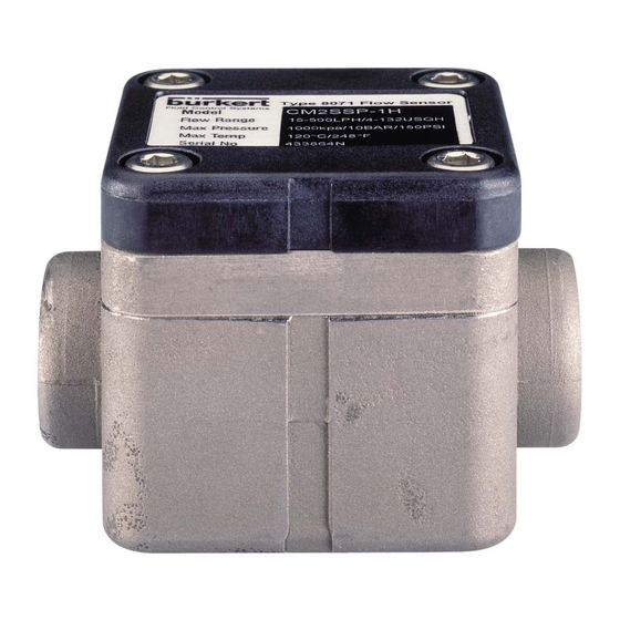
Fig. 1: Running/displacement of oval rotors The remote instrument converts the frequency into a flow rate by using the correct K factor. 5.3. Description of the name plate Type 8071 Flow Sensor Model 433864N Flow Range 2-100LPH Max Pressure 1000kPa/55Bar Max Temp 120°C... -
Page 9: Available Versions
Type 8071 Description 5.4. Available versions flow rate range materials process max. viscosity order code viscosity connection pressure > 5 mpa.s and housing rotors / axis seal < 5 mpa.s < 1000 mpa.s G 1/8'' 0.5-100 l/h 2-100 l/h Aluminium Stainless steel 5 bar 565117 Stainless steel Stainless steel FFKM 55 bar... - Page 10 Type 8071 Description flow rate range materials process max. order code connection pressure viscosity > 1000 mpa.s housing rotors / axis seal G 1/4'' 15-500 l/h Stainless steel Stainless steel FFKM 55 bar 552426 553652 NPT 1/4'' 15-500 l/h Stainless steel Stainless steel FFKM 55 bar High pressure versions available on request...
-
Page 11: Technical Data
Type 8071 Technicaldata TechnicAl DATA 6.2.2. General data Process connection Internal thread G 1/8" or G 1/4", 6.1. conditions of use NPT 1/8’’or NPT 1/4’’ Ambient temperature Max. fluid pressure • Aluminium or PPS housing • max. 80 °C • PPS or aluminium housing •... -
Page 12: Dimensions
Type 8071 Technicaldata 6.2.3. electrical data 6.3. Dimensions Supply voltage 4,5- 24 V DC 51/51/60* 51/51/60* Tansistor output • Frequency on open collector, • Type of output NPN, max. 25 mA, 4,5 to 24 V DC • Hall sensor max. intensity •... -
Page 13: K Factors (In Pulse/L)
Type 8071 InstallationandWiring 6.4. K factors (in pulse/l) insTAllATion AnD WirinG Flow rate range K factor (in pulse/l) 7.1. safety instructions 0.5- 100 l/h 1000 15- 500 l/h danger If the device is combined with an instrument which does not risk of injury due to high pressure in the installation. -
Page 14: Installation Instructions
Type 8071 InstallationandWiring Warning note the oval rotors may be damaged if particles with dia- risk of injury due to non-conforming installation. meter > 75 µm go into the fitting. • The electrical and fluid installation can only be carried out by • Install a strainer of 75 µm upstream and as close as possible to qualified and skilled staff with the appropriate tools. -
Page 15: Wiring
Type 8071 InstallationandWiring 7.3. Wiring 7.3.1. Wiring the npn transistor output and the reed switch output danger L+ (4,5 - 24 V DC) risk of injury due to electrical voltage. V DC (red wire) • Shut down and isolate the electrical power source before L- (black wire) yellow wire carrying out work on the system. -
Page 16: Commisioning
Type 8071 Commisioning commisioninG mAinTenAnce AnD TroubleshooTinG 8.1. safety instructions 9.1. safety instructions Warning danger risk of injury due to nonconforming commissioning. Non conforming commissioning may lead to injuries and damage risk of injury due to high pressure in the installation. the device and its surroundings. • Stop the circulation of fluid, cut off the pressure and drain the •... -
Page 17: Maintenance Of The Strainer
Type 8071 Maintenanceandtroubleshooting 9.4. Dismantle the device Warning risk of injury due to non-conforming maintenance. grooves • Maintenance must only be carried out by qualified and skilled staff with the appropriate tools. • Guarantee a set or controlled restarting of the process, after a power supply interruption. -
Page 18: Assemble The Device
Type 8071 Maintenanceandtroubleshooting 9.5. Assemble the device Put the magnetized rotor on the same side as the groove (see Fig. 8 and table below). → Put the rotors inside the housing, at 90° (see Fig. 8). groove right angle Magnetized oval rotor... -
Page 19: If A Problem Occurs
Type 8071 Maintenanceandtroubleshooting 9.6. if a problem occurs Problem Cause Solution → Fluid does not Obturated device Remove and clean the oval rotors (see chap. "9.4. Dismantle the device" and flow through the "9.5. Assemble the device"). device any more →... -
Page 20: Spare Parts And Accessories
Type 8071 Sparepartsandaccessories spAre pArTs AnD spare part order code Accessories Cover in PPS with electronic module including 553654 Hall effect sensor and Reed switch caution Cover in aluminium with electronic module on request risk of injury and damage caused by the use of unsuitable including Hall effect sensor and Reed switch parts. -
Page 21: Packaging, Transport
Type 8071 Packaging,Transport pAcKAGinG, TrAnsporT DisposAl of The Device → Dispose of the device and its packaging in an environmentally- note friendly way. Damage due to transport note Transport may damage an insufficiently protected device. • Transport the device in shock-resistant packaging and away Damage to the environment caused by products contami- from humidity and dirt. - Page 22 Type 8071 English...
- Page 23 Type 8071 English...
- Page 24 Type 8071 English...
- Page 25 Typ 8071 Typ 8071 1. Die BeDienungsanleitung .............. 4 7. installation unD VerKaBelung ..........13 1.1. Darstellungsmittel ................4 7.1. sicherheitshinweise ..............13 1.2. Begriffsdefinition "gerät" ............... 4 7.2. empfehlungen für die installation .......... 14 7.3. Verkabelung ..................15 2. Bestimmungsgemässe VerwenDung ........5 8. inBetrieBnahme ..................16 3. grunDlegenDe sicherheitshinweise .
-
Page 26: Die Bedienungsanleitung
Arbeitsschritt, den Sie ausführen müssen. • Bei Nichteinhaltung sind Tod oder schwere Verletzungen die Folge. 1.2. Begriffsdefinition "gerät" WarnunG! Der in dieser Anleitung verwendete Begriff "Gerät" steht immer für das Durchfluss-Messgerät Typ 8071. warnt vor einer möglicherweise gefährlichen situation! • Bei Nichteinhaltung drohen schwere Verletzungen oder Tod. deutsch... -
Page 27: Bestimmungsgemässe Verwendung
Typ 8071 BestimmungsgemässeVerwendung BesTimmungsgemässe grunDlegenDe VerwenDung sicherheiTshinweise Diese Sicherheitshinweise berücksichtigen keine Bei nicht bestimmungsgemäßem einsatz des gerätes können • Zufälligkeiten und Ereignisse, die bei Montage, Betrieb und Wartung gefahren für Personen, anlagen in der umgebung und die der Geräte auftreten können. umwelt entstehen. • Ortsbezogenen Sicherheitsbestimmungen, für deren Einhaltung, • Das Gerät ist zur Durchflussmessung von Flüssigkeiten, insbe- auch in Bezug auf das Installations- und Wartungspersonal, der sondere viskosen Flüssigkeiten bestimmt. - Page 28 Typ 8071 GrundlegendeSicherheitshinweise hInWeIS! Das gerät kann durch das medium beschädigt werden. allgemeine gefahrensituationen. • Kontrollieren Sie systematisch die chemische Verträglichkeit der Zum Schutz vor Verletzungen ist zu beachten: Werkstoffe, aus denen das Gerät besteht, und der Flüssigkei- • Nach einer Unterbrechung der elektrischen Versorgung ist ein ten, die mit diesem in Berührung kommen können (zum Beispiel: definierter oder kontrollierter Wiederanlauf des Prozesses zu Alkohole, starke oder konzentrierte Säuren, Aldehyde, Basen,...
-
Page 29: Allgemeine Hinweise
Reed-Schalter auf. 4.3. informationen im internet Der elektrische Anschluss erfolgt über einen 1m-langen 5-adrigen Kabel. Bedienungsanleitungen und Datenblätter zum Typ 8071 finden Sie im Internet unter: www.buerkert.de 5.2.2. messprinzip Die durch die Rohrleitung fließende Flüssigkeit bewirkt das Drehen der Ovalräder, die Magnete enthalten (siehe Bild 1). -
Page 30: Beschreibung Des Typenschilds
Typ 8071 Beschreibung Reed-Schalter-Ausgang verfügbar. Bild 1: Funktionsweise/Bewegung der Ovalräder Das abgesetzte Instrument konvertiert die Frequenz mit dem geei- gneten K-Faktor in einen Durchflusswert. 5.3. Beschreibung des Typenschilds Type 8071 Flow Sensor Model 433864N Flow Range 2-100LPH Max Pressure 1000kPa/55Bar 120°C... -
Page 31: Verfügbare Versionen
Typ 8071 Beschreibung 5.4. Verfügbare Versionen Durchfluss-messbereich werkstoffe Prozess- max. Viskosität Bestellnummer Viskosität anschluss Druck > 5 mPa.s und gehäuse räder / achse Dichtung < 5 mPa.s < 1000 mPa.s G 1/8'' 0.5-100 l/h 2-100 l/h Aluminium Edelstahl 5 bar 565117 Edelstahl Edelstahl FFKM 55 bar 565118 NPT 1/8'' 0.5-100 l/h... - Page 32 Typ 8071 Beschreibung Durchfluss-messbereich werkstoffe Prozess- max. Bestell- anschluss Druck nummer Viskosität > 1000 mPa.s gehäuse räder / achse Dichtung G 1/4'' 15-500 l/h Edelstahl Edelstahl FFKM 55 bar 552426 553652 NPT 1/4'' 15-500 l/h Edelstahl Edelstahl FFKM 55 bar Hochdruckversion auf Anfrage erhältlich Weitere Hochviskosität-Versionen auf Anfrage erhältlich...
-
Page 33: Technische Daten
Typ 8071 TechnischeDaten Technische DaTen 6.2.2. allgemeine Daten Prozess-Anschluss Innengewinde, G 1/8", G 1/4", 6.1. Betriebsbedingungen NPT 1/8’’oder NPT 1/4’’ Umgebungs-Temperatur Max. Flüssigkeitsdruck • Gehäuse aus Aluminium • max. 80 °C • Gehäuse aus PPS oder • 5 bar oder PPS Aluminium •... -
Page 34: Abmessungen
Typ 8071 TechnischeDaten 6.2.3. elektrische Daten 6.3. abmessungen Betriebsspannung 4,5 - 24 V DC 51/51/60* 51/51/60* Transistor-Ausgang • Frequenz über Open Kol- • Ausgangs-Typ lektor, NPN, max. 25 mA, 4,5 bis 24 V DC • Max. Intensität des • 25 mA... -
Page 35: K-Faktoren (In Pulse/Liter)
Typ 8071 InstallationundVerkabelung 6.4. K-Faktoren (in Pulse/liter) insTallaTion unD VerKaBelung Durchfluss-Messbereich K-Faktor (in Pulse/Liter) 0.5- 100 l/h 1000 7.1. sicherheitshinweise 15- 500 l/h Gefahr! Wenn das Gerät mit einem Instrument verbunden ist, das die K-Faktoren nicht automatisch umrechnet, die Verletzungsgefahr durch hohen Druck in der anlage! Umrechnung mit einer der folgenden Formeln vornehmen: •... -
Page 36: Empfehlungen Für Die Installation
Typ 8071 InstallationundVerkabelung WarnunG! hInWeIS! gefahr der Beschädigung der ovalräder, wenn Partikel mit Verletzungsgefahr bei unsachgemäßer installation! einem Durchmesser > 75 µm in den sensor gelangen. • Fluidische und elektrische Installationen dürfen nur durch auto- • Einen 75-µm-Filter so dicht wie möglich vor dem Gerät risiertes Fachpersonal und mit geeignetem Werkzeug durchge- führt werden! installieren. • Verwenden Sie unbedingt geeignete Sicherheitsvorrichtun- →... -
Page 37: Verkabelung
Typ 8071 InstallationundVerkabelung 7.3. Verkabelung 7.3.1. anschluss des nPn- Transistorausgangs und des Gefahr! reed-schalterausgangs Verletzungsgefahr durch stromschlag! L+ (4,5 - 24 V DC) V DC • Schalten Sie vor Beginn der Arbeiten in jedem Fall die Span- (rote Ader) nung ab, und sichern Sie diese vor Wiedereinschalten! -
Page 38: Inbetriebnahme
Typ 8071 Inbetriebnahme inBeTrieBnahme warTung, ProBlemlösung 8.1. sicherheitshinweise 9.1. sicherheitshinweise WarnunG! Gefahr! Verletzungsgefahr bei unsachgemäßer inbetriebnahme! Verletzungsgefahr durch hohen Druck in der anlage! • Vor dem Lösen der Prozessanschlüsse die Anlage druckfrei Nicht sachgemäße Inbetriebnahme kann zu Verletzungen sowie schalten und die Flüssigkeitszirkulation stoppen. Schäden am Gerät und seiner Umgebung führen. -
Page 39: Wartung Des Filters
Typ 8071 Wartung,Problemlösung Wenn Sie ergänzende Informationen wünschen, steht Ihnen Ihr Lie- WarnunG! ferant Bürkert voll und ganz zur Verfügung. gefahr durch unsachgemäße wartungsarbeiten! 9.4. ausbau des gerätes • Wartungsarbeiten dürfen nur durch autorisiertes Fachpersonal und mit geeignetem Werkzeug durchgeführt werden! • Nach einer Unterbrechung der elektrischen Versorgung ist ein... -
Page 40: Wiederaufbau Des Gerätes
Typ 8071 Wartung,Problemlösung 9.5. wiederaufbau des gerätes Das mit dem Magnet versehene Rad muss wieder auf der Seite mit der Rille eingesetzt werden (siehe Bild 8 und die folgende Tabelle). → Die um 90° gegeneinander versetzten Räder wieder in das Gehäuse einsetzen (siehe Bild 8). -
Page 41: Problemlösung
Typ 8071 Wartung,Problemlösung 9.6. Problemlösung Problem Ursache Lösung → Die Flüssigkeit Gerät verstopft Die Räder demontieren und reinigen (siehe Kap. "9.4. Ausbau des Gerätes" läuft nicht mehr und "9.5. Wiederaufbau des Gerätes"). durch das Gerät → 75-µm-Filter vor dem Gerät einbauen. -
Page 42: Ersatzteile, Zubehör
Typ 8071 Ersatzteile,Zubehör ersaTzTeile, zuBehör ersatzteil Bestellnummer Deckel aus Aluminium mit Elektronikmodul mit auf Anfrage VOrSIChT! Hallsensor und Reed-Schalter Verletzungsgefahr, sachschäden durch ungeeignete teile! Falsches Zubehör und ungeeignete Ersatzteile können Ver- letzungen und Schäden am Gerät und dessen Umgebung verursachen. • Verwenden Sie nur Originalzubehör sowie Originalersatzteile der Fa. -
Page 43: Verpackung, Transport
Typ 8071 Verpackung,Transport VerPacKung, TransPorT enTsorgung Des geräTes → Entsorgen Sie das Gerät und die Verpackung umweltgerecht. hInWeIS! hInWeIS! transportschäden! Ein unzureichend geschütztes Gerät kann durch den Transport umweltschäden durch teile, die durch Flüssigkeiten kontami- beschädigt werden. niert wurden! • Transportieren Sie das Gerät vor Nässe und Schmutz geschützt •... - Page 44 Typ 8071 deutsch...
- Page 45 Typ 8071 deutsch...
- Page 46 Typ 8071 deutsch...
- Page 47 Type 8071 Type 8071 1. À propos de ce manuel ..............4 7. installation et câblage électrique ......... 13 1.1. symboles utilisés ................4 7.1. consignes de sécurité ..............13 1.2. définition du terme "appareil" ............. 4 7.2. recommandations d'installation ..........14 7.3. câblage électrique ................. 15 2. utilisation conforme................. 5 8. mise en serVice ..................16 3. consignes de sécurité de base .
-
Page 48: À Propos De Ce Manuel
Type 8071 Àproposdecemanuel À propos de ce manuel attention Ce manuel décrit le cycle de vie complet de l'appareil. Conservez-le met en garde contre un risque éventuel. de sorte qu'il soit accessible à tout utilisateur et à disposition de tout • Son non-respect peut entraîner des blessures légères ou de nouveau propriétaire. -
Page 49: Utilisation Conforme
Type 8071 Utilisationconforme uTilisaTion conforme consignes de sécuriTé de base l'utilisation non conforme de l'appareil peut présenter des Ces consignes de sécurité ne tiennent pas compte : dangers pour les personnes, les installations proches et • des imprévus pouvant survenir lors de l'assemblage, de l'utilisation l‘environnement. et de l'entretien des appareils. • L'appareil est destiné à la mesure du débit de liquides, particu- lièrement de liquides visqueux. - Page 50 Type 8071 Consignesdesécuritédebase remarque l'appareil peut être endommagé par le fluide en contact. situations dangereuses diverses • Vérifier systématiquement la compatibilité chimique des maté- Pour éviter toute blessure, veiller à : riaux composant l'appareil et les produits susceptibles d’entrer • garantir un redémarrage défini et contrôlé du process, après en contact avec celui-ci (par exemple : alcools, acides forts ou une coupure de l'alimentation électrique.
-
Page 51: Informations Générales
Reed. Le raccordement électrique s'effectue à l'aide d'un câble à 5 fils d'un Retrouvez sur internet les manuels utilisateur et les fiches techniques mètre de long. relatifs au type 8071 sous : www.burkert.fr/ 5.2.2. principe de fonctionnement Le fluide circulant dans la canalisation fait tourner les roues ovales qui contiennent des aimants (voir Fig. -
Page 52: Description De L'étiquette D'identification
Model 433864N Flow Range 2-100LPH Max Pressure 1000kPa/55Bar Max Temp 120°C Serial No D34128 Fig. 2 : Étiquette d'identification du débitmètre 8071 Référence de commande de l'appareil Plage de mesure du débit Pression max. Température max. Numéro de série français... -
Page 53: Versions Disponibles
Type 8071 Description 5.4. Versions disponibles plage de débit matériaux raccordement pression référence de viscosité viscosité au process max. commande > 5 mpa.s et boîtier roues / axe joint < 5 mpa.s < 1000 mpa.s G 1/8'' 0.5-100 l/h 2-100 l/h aluminium acier inoxydable 5 bar 565117 acier inoxydable acier inoxydable FFKM 55 bar... - Page 54 Type 8071 Description plage de débit matériaux raccordement pression référence de au process max. commande viscosité > 1000 mpa.s boîtier roues / axe joint G 1/4'' 15-500 l/h acier inoxydable acier inoxydable FFKM 55 bar 552426 553652 NPT 1/4'' 15-500 l/h acier inoxydable acier inoxydable FFKM 55 bar Versions haute pression disponibles sur demande Autres versions pour haute viscosité...
-
Page 55: Caractéristiques Techniques
Type 8071 Caractéristiquestechniques caracTérisTiques élément matériau Techniques • Hastalloy C • Acier inoxydable 316F (1.4401) 6.1. conditions d'utilisation Joint FKM ou FFKM Température ambiante • boîtier en aluminium ou • max. 80 °C 6.2.2. caractéristiques générales en PPS Raccordement au process Taraudage G 1/8"... -
Page 56: Dimensions
Type 8071 Caractéristiquestechniques 6.2.3. caractéristiques électriques 6.3. dimensions Tension d'alimentation 4,5 - 24 V DC 51/51/60* 51/51/60* Sortie transistor : • Fréquence sur collecteur • Type de sortie ouvert, NPN, max. 25 mA, 4,5 à 24 V DC • Intensité max. du capteur Hall •... -
Page 57: Facteurs K (En Imp./L)
Type 8071 Installationetcâblageélectrique 6.4. facteurs K (en imp./l) insTallaTion eT câblage élecTrique Plage de débit Facteur K (imp./l) 0.5 - 100 l/h 1000 7.1. consignes de sécurité 15 - 500 l/h danger Si l'appareil est raccordé à un instrument qui ne convertit pas automatiquement les facteurs K, effectuer la conversion risque de blessure dû à la pression élevée dans l'installation. -
Page 58: Recommandations D'installation
Type 8071 Installationetcâblageélectrique avertissement remarque risque d'endommager les roues ovales si des particules de risque de blessure dû à une installation non conforme. diamètre > 75 µm entrent dans l'appareil. • L'installation électrique et fluidique ne peut être effectuée • Installer un filtre de 75 µm en amont et aussi près que possible que par du personnel habilité et qualifié, disposant des outils appropriés. - Page 59 Type 8071 Installationetcâblageélectrique 7.3. câblage 7.3.1. câblage de la sortie transistor npn et de la sortie interrupteur reed danger L+ (4,5 - 24 V DC) risque de blessure par décharge électrique. V DC (fil rouge) • Couper et consigner l'alimentation électrique avant d'intervenir L- (fil noir) fil jaune sur l'installation.
-
Page 60: Mise En Service
Type 8071 Miseenservice mise en serVice mainTenance eT dépannage 8.1. consignes de sécurité 9.1. consignes de sécurité avertissement danger risque de blessure dû à une mise en service non conforme. La mise en service non conforme peut entrainer des blessures et risque de blessure dû à la pression élevée dans l'installation. endommager l'appareil et son environnement. • Stopper la circulation du fluide, couper la pression et purger la •... -
Page 61: Entretien Du Filtre
Type 8071 MaintenanceetdÉpannage 9.4. démonter l'appareil avertissement danger dû à une maintenance non conforme. rainures • Ces travaux doivent être effectués uniquement par du personnel qualifié et habilité, disposant des outils appropriés. • Après toute coupure de l'alimentation électrique, garantir un redémarrage défini ou contrôlé du process. -
Page 62: Remonter L'appareil
Type 8071 MaintenanceetdÉpannage 9.5. remonter l'appareil Replacer la roue aimantée du même côté que la rainure (voir Fig. 8 et tableau ci-dessous). → Replacer les roues dans le boîtier, à 90° l'une par rapport à l'autre (voir Fig. 8). angle droit... -
Page 63: En Cas De Problème
Type 8071 MaintenanceetdÉpannage 9.6. en cas de problème Problème Cause Solution → Fluide ne Appareil obturé Démonter et nettoyer les roues (voir chap. "9.4. Démonter l'appareil" et "9.5. s'écoule plus à Remonter l'appareil"). travers l'appareil → Ajouter filtre de 75 µm en amont de l'appareil →... -
Page 64: Pièces De Rechange Et Accessoires
Type 8071 Piècesderechangeetaccessoires pièces de rechange eT référence de pièce de rechange accessoires commande Couvercle en acier inoxydable avec module 553653 attention électronique incluant le capteur à effet Hall et l'interrupteur Reed risque de blessure et de dommage matériel dus à l'utilisation de fausses pièces. Couvercle en PPS avec module électronique 553654 incluant le capteur à effet Hall et l'interrupteur Un mauvais accessoire ou une pièce de rechange inadaptée... -
Page 65: Emballage Et Transport
Type 8071 Emballageettransport emballage eT TransporT éliminaTion de l’appareil → Éliminer l’appareil et l’emballage dans le respect de remarque l’environnement. dommages dus au transport remarque Le transport peut endommager un appareil insuffisamment protégé. dommages à l'environnement causés par des pièces conta- • Transporter l'appareil dans un emballage résistant aux chocs, à... - Page 66 Type 8071 français...
- Page 68 www.burkert.com...
Need help?
Do you have a question about the 8071 and is the answer not in the manual?
Questions and answers