Graco ultra max 795 Instruction Manual
Airless
Hide thumbs
Also See for ultra max 795:
- Operation (9 pages) ,
- Instructions-parts list manual (36 pages) ,
- Instructions and parts list (28 pages)
Table of Contents
Advertisement
Parts
INSTRUCTIONS-REPAIR
KEEP FOR REFERENCE.
Read this and all related manuals for
important warnings and instructions.
INSTRUCTIONS
ULTRArMAX 795 and 1095
Airless Paint Sprayers
3000 psi (210 bar, 21 MPa ) Maximum Working Pressure
230 VAC
Model
Series Description
232144
A
Ultra Max 795
Hi-boy with RAC IV tip, gun and hose
232145
A
Ultra Max 795
Lo-boy with RAC IV tip, gun and hose
232154
A
Ultra Max 1095
Hi-boy with RAC IV tip, gun and hose
110 VAC
Model
Series Description
232148
A
Ultra Max 795
Hi-boy with RAC IV tip, gun and hose
232158
A
Ultra Max 1095
Hi-boy with RAC IV tip, gun and hose
100 VAC
Model
Series Description
232156
A
Ultra Max 1095 Hi-boy
232157
A
Ultra Max 1095 Lo-boy
Component Function and Identification
. . . . . . . . . . . . . . . . . . . . . . . . . . . . . . . . . . . . .
. . . . . . . . . . . . . . . . . . . . . . . . . . . . . . . .
. . . . . . . . . . . . . . . . . . . . . . . . . . . . . . . . . . . . . .
General Repair Information
GRACO INC. P.O. BOX 1441 MINNEAPOLIS, MN 55440-1441
Table of Contents
. . . . . . . . . . . .
. . . . . . . . . . . . . . . . . . . . . .
. . . . . . . . . . . . . . . . . . . . . .
. . . . . . . . . . . . . . . . . . . .
. . . . . . . . . . . . . . . . . . . . . . .
.
. . . . . . . . . . . . . . . . . . . .
ECOPYRIGHT 1998, GRACO INC.
Graco Inc. is registered to I.S. EN ISO 9001
First choice when
quality counts.t
Model 232144
All models are not available in all countries
U.S. PATENT NO. 4,323,741; 4,397,610 PATENTED
1983, CANADA AND OTHER PATENTS PENDING
Related Manuals
Operator
. . . . . . . . . . . . . . . . . . . . . . . . . . .
Displacement Pump
Spray Gun
. . . . . . . . . . . . . . . . . . . . . . . . .
Spray Tip
. . . . . . . . . . . . . . . . . . . . . . . . . . .
PC Board
. . . . . . . . . . . . . . . . . . . . . . . . . .
2
4
4
9
3
. . . . . . . . . . . . . . . . . . . . . . . . . . . . . . .
9
. . . . . . . . . . . . . . . . . . . . . . . . . . . . . . . . . .
11
. . . . . . . . . . . . . . . . . . . . . . . . . . . . . . . .
12
. . . . . . . . . . . . . . . . . . . . . . . . . . . . . . . . . . .
14
15
Graco Warranty
. . . . . . . . . . . . . . . . . . . . . . . . . . . . . . .
308842
308840
. . . . . . . . . . . . . . . . .
308798
307614
308644
308816
. . . . . . . . . . . . . . . . . . . . . . . . . . . .
. . . . . . . . . . . . . . . . . . . . .
. . . . . . . . . . . . . . . . . . . . . . .
. . . . . . . . . . . . . . . . . . . . . . . . . . .
. . . . . . . . . . . . . . . . . . . . . . . . . .
Rev. H
8050A
16
17
18
19
23
24
24
24
24
24
Advertisement
Table of Contents

Related Manuals for Graco ultra max 795


Summary of Contents for Graco ultra max 795
-
Page 1: Table Of Contents
....... GRACO INC. P.O. BOX 1441 MINNEAPOLIS, MN 55440–1441 ECOPYRIGHT 1998, GRACO INC. Graco Inc. is registered to I.S. EN ISO 9001... -
Page 2: Component Identification And Function
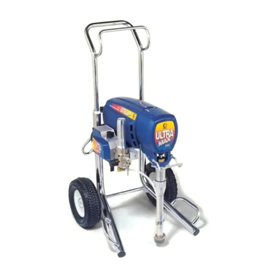
Component Identification and Function 03008 Fig. 1 8050A Motor DC motor, permanent magnet, totally enclosed, fan cooled Drive Assembly Transfers power from DC motor to displacement pump Pail Hanger Container for fluid to be sprayed may be hung here Displacement Pump Transfers fluid to be sprayed from source through spray gun Primary Fluid Outlet Single spray gun is connected here... - Page 3 General Repair Information WARNING CAUTION To reduce risk of pressure control malfunction: EXPLOSION HAZARD Motor and drive housing are very hot Use needle nose pliers to disconnect a wire. Never during operation and could burn skin if pull on wire, pull on connector. touched.
-
Page 4: Grounding
Grounding WARNING Grounded Grounding Plug Outlets Improper installation or alteration of grounding plug results in risk of electric shock, fire or explosion that could cause serious injury or death. 1. Models 232144, 145, 154 require a 230 VAC, 50 Hz, 10A circuit with a grounding receptacle. Mod- Model 232144, 145, 154 els 232148, 158 require a 110 VAC, 50/60 Hz, 15A Fig. - Page 5 Troubleshooting MOTOR WON’T OPERATE (Continued) TYPE OF PROBLEM WHAT TO CHECK WHAT TO DO If check is OK, go to next check When check is not OK refer to this column Basic Electrical Problems 1. That motor leads are securely fastened and 1.
-
Page 6: Low Output
Troubleshooting LOW OUTPUT TYPE OF PROBLEM WHAT TO CHECK WHAT TO DO If check is OK, go to next check When check is not OK refer to this column Low Output 1. For worn spray tip. 1. Follow Pressure Relief Procedure Warn- ing, then replace tip. - Page 7 Troubleshooting NO OUTPUT TYPE OF PROBLEM WHAT TO CHECK WHAT TO DO If check is OK, go to next check When check is not OK refer to this column Motor runs and pump strokes 1. Paint supply. 1. Refill and reprime pump. 2.
- Page 8 Troubleshooting MOTOR IS HOT AND RUNS INTERMITTENTLY TYPE OF PROBLEM WHAT TO CHECK WHAT TO DO If check is OK, go to next check When check is not OK refer to this column Motor is hot and runs intermit- 1. Determine if sprayer was operated at high 1.
-
Page 9: Spin Test
Spin Test Setup Armature, Brushes, and Motor Wiring Open Circuit Test (Continuity) 1. Connect red and black motor leads together with Electric Shock Hazard; page 3. test lead. Turn motor fan by hand at about two revolutions per second. To check armature, motor winding and brush electrical 2. - Page 10 Motor Brush Replacement 4. Fig. 5. Push in 110816 spring clip (A) to release 10. Fig. 6. Install spring clip (A). Push down to hook hooks (B) from brush holder (C). Pull out spring short slots (K) in brush holder (C). clip.
-
Page 11: On/Off Switch Replacement
On/Off Switch Replacement 1. Read General Repair Information on page 3. 6. Press in on two retaining tabs on each side of ON/OFF switch (80) and remove. 7. Install new ON/OFF switch (80) so tabs of switch Relieve pressure; page 3. snap into place on inside of pressure control housing. -
Page 12: Pressure Control Repair
Pressure Control Repair Motor Control Board Removal Installation 1. Fig. 7. Install motor control board (104) with four screws (102). Relieve pressure; page 3. 2. Connect to motor control board (104): D Lead (E) to transducer. 2. Fig. 7. Remove five screws (28) and cover (82). 3. - Page 13 Pressure Control Repair Digital Display Messages No display does not mean 1. Lift lid on pressure control cover and view display. that sprayer is not pressur- 2. Observe display and reference following table: ized. Relieve pressure before repairing; page 3. DISPLAY SPRAYER INDICATION...
-
Page 14: Bearing Housing & Connecting Rod Replacement
Bearing Housing and Connecting Rod Replacement 1. Read General Repair Information on page 3. CAUTION Do not use bearing housing screws (25) to align or Relieve pressure; page 3. seat bearing housing; this may cause bearing and drive housing misalignment and result in premature bearing wear. -
Page 15: Drive Housing Replacement
Drive Housing Replacement 6. Remove two drive housing screws (26) and CAUTION lockwashers (20). Do not drop gear cluster (51) when removing drive 7. Remove two lower screws (16) and lockwashers housing (67). Gear cluster may stay engaged in (20) and then two upper screws (16) and lock- motor front end bell or drive housing. -
Page 16: Motor Replacement
Motor Replacement 1. Read General Repair Information on page 3. CAUTION Do not drop gear cluster (51) when removing drive housing (67). Gear cluster may stay engaged in Relieve pressure; page 3. motor front end bell or drive housing. Do not lose thrust balls (90) or drop thrust balls between gears. -
Page 17: Displacement Pump Repair
1. Fig. 14. Pull piston rod out 1.5 in. Screw in pump until holes in bearing cross link and piston rod align. Fig. 15 7673B Fig. 16. Fill packing nut with Graco TSL, through one of the slits, until fluid flows onto the top of seal. 1.5 in. Fig. 14 7676B 7677B Fig. -
Page 18: Parts Drawing - Sprayer
Parts Drawing – Sprayer Ultra MAX 795 and 1095 Hi-boy Sprayers Model 232144, Series A Model 232154, Series A Model 232148, Series A Model 232158, Series A Model 232156, Series A 73a* Ref 70 Ref 120 SEE PARTS ON PAGE 22... -
Page 19: Parts List - Sprayer
Parts List – Sprayer Ultra MAX 795 and 1095 Hi-boy Sprayers Model 232144, Series A; Model 232154, Series A Model 232148, Series A; Model 232156, Series A; Model 232158, Series A NO. PART NO. DESCRIPTION NO. PART NO. DESCRIPTION 110996 NUT, heavy hex, 5/16–18 unc–2a... - Page 20 Parts Drawing – Sprayer Ultra MAX 795 and 1095 Lo-Boy Sprayers Model 232145, Series A Model 232157, Series A 19 14 21 Ref 70 Ref 43 SEE PARTS ON PAGE 22 Ref 85 8126A 308842...
- Page 21 Parts List – Sprayer Ultra MAX 795 and 1095 Lo-Boy Sprayers Model 232145, Series A; Model 232157, Series A NO. PART NO. DESCRIPTION NO. PART NO. DESCRIPTION 110996 NUT, flange head, hex 239923 PUMP, displacement 101242 RING, retaining see manual 308798 for parts 100644 SCREW, socket head, 1/4–20 x 3/4 in.
- Page 22 Parts Drawing – Sprayer Ultra MAX 795 and 1095 Sprayers Model 232144, Series A Model 232145, Series A Model 232148, Series A Model 232154, Series A Model 232156, Series A Model 232157, Series A Model 232158, Series A 8056C Model 232–148 and 232–158 only...
-
Page 23: Wiring Diagram
Parts List – Sprayer Ultra MAX 795 and 1095 Sprayers Models 232144, Series A; 232145, Series A; 232148, Series A Models 232154, Series A; 232158, Series A; 232157, Series A; 232156, Series A NO. PART NO. DESCRIPTION NO. PART NO. -
Page 24: Accessories
TO PLACE AN ORDER, contact your Graco distributor. All written and visual data contained in this document reflect the latest product information available at the time of publication. Graco reserves the right to make changes at any time without notice. Sales Offices: Minneapolis, Detroit International Offices: Belgium, Korea, Hong Kong, Japan www.graco.com...
Need help?
Do you have a question about the ultra max 795 and is the answer not in the manual?
Questions and answers