Table of Contents
Advertisement
Quick Links
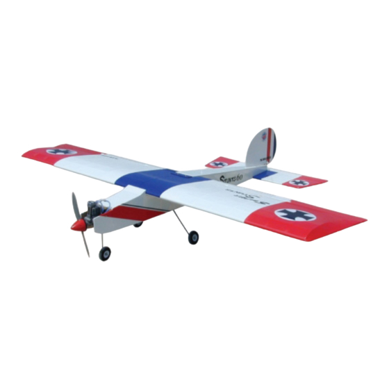
Super Stunts 60
0.6
0-0.75
Requires : 4 channel radio w 5 standard servos
Wing Span
Wing Area
Flying Weight
Fuselage Length
Warning !This model is not a toy.
It is designed for maximum performance. Please seek advice if one is not familiar with this kind
of engine powered precision model. Operating this model without prior preparation may cause
injuries. Remember, safety is the most important thing. Always keep this instruction manual at
hand for quick reference.
cu. in. displacement 2-stroke
-
Specifications
* Specifications are subject to change without notice.*
INSTRUCTION MANUAL
/
80 in / 2030 mm
1337 sq in / 86.3 sq dm
8.0 lbs / 3550 g
68.5 in / 1740 mm
FACTORY PRE-FABRICATED
ALMOST-READY-TO-FLY (ARF) SERIES
MADE IN CHINA
Advertisement
Table of Contents

Related Manuals for The World Models Manufacturing Super Stunts 60


Summary of Contents for The World Models Manufacturing Super Stunts 60
- Page 1 INSTRUCTION MANUAL Super Stunts 60 0-0.75 cu. in. displacement 2-stroke Requires : 4 channel radio w 5 standard servos Specifications Wing Span 80 in / 2030 mm Wing Area 1337 sq in / 86.3 sq dm Flying Weight 8.0 lbs / 3550 g Fuselage Length 68.5 in / 1740 mm...
-
Page 2: Before You Begin
Super Stunts 60 I N D E X BEFORE YOU BEGIN P. 1 PARTS LIST P. 2 ASSEMBLY P. 3 - 11 SAFETY PRECAUTIONS P. 11 BEFORE YOU BEGIN Read through the manual before you begin, so you will have an overall idea of what to do. -
Page 3: Parts List
Parts List 1.MAIN WING -- 1 pair M4x30mm -- 4 pcs SOCKET HEAD SCREW WASHER d4xD9mm -- 8 pcs 2.SCREW PB2x20mm -- 8 pcs M4 NUT -- 8 pcs 6x5mm -- 8 pcs FUEL TUBE Ø 62mm -- 1 pc. SPINNER Ø... - Page 4 Apply instant type CA glue to both sides of each hinge. Main Wing Ø1mm pilot holes for World Models tri-horn are pre-drilled. Please look for pin-holemarks at under side of control surfaces. Aileron & Flap Servos Pushrod Ø1.8x165mm Straper PB2x20mm Screw Fuel Tube Ø6x5mm Lead for servo...
- Page 5 Stabilizer & Elevator Apply instant type CA glue to both sides of each hinge. PM3x22mm PM3x22mm Screw d3xD7mm Washer d3xD7mm Balsa 6x245mm (Stabilizer) (Main Wing) B=B' Temporary install the main wing, adjust leveling of the stabilizer to make it as parallel to the main wing as possible.
-
Page 6: Fuel Tank
Fuel Tank Setup Fuel Tank Balsa 10x10x109mm Fuel Tank 380cc (For Fuel Tank Position F ixing ) Fuel Tank 380cc Top View Engine Mount M4x25mm Socket Head Screw Engine Mount PL5111-070 d4xD9mm Washer Blind nuts are off-centered to keep the spinner at the fuselage axis. Apply thread locker to screws Washer d4xD9mm... -
Page 7: Front Wheel
Front Wheel Ø1.6x490mm(Frint wheel Pushrod) 3mm Set Screw 3mm Set Screw Set Screw 4.1mm Collar Wheel Ø70 Completed 3mm Set Screw Front View PA3x12mm Landing Gear PA3x12mm Screw Landing Gear Main Landing Gear 3mm Set Screw Ø4mm 4.1mm Collar Wheel Ø70mm 4.1mm Collar 3mm Set Screw... - Page 8 IIIustration is for upright mounting. M4x30mm Engine You can mount the engine inverted simply by rotating the engine mount. Thrust angles will not be affected. M4x mm Socket Head Screw d4xD9mm d4xD9mm Washer Washer Install Engine position Spinner M4 Nut Ø62mm Plastic tube 136mm...
-
Page 9: Rudder Pullwire
Rudder Pullwire PM2x16mm Screw Ø 1mm pilot holes for World Models tri-horn are pre-drilled. Please look for pin-holemarks at side of control 2mm Nut Copper Tube surfaces. d2.5xD3.2x8mm RIGGING COUPLER Ø1.8x27mm Fuel Tube Ø6x5mm 2mm Nut PM2x16mm Elevator Pushrod PB2x16mm PB2x16mm Screw Ø... -
Page 10: Radio Equipment
Radio Equipment Install Pinch the servo as shown in the diagram. Copper Tube Press down the center 1/ 3 portion Charge Receptacles KP0041300 Balsa Front 6x8x37mm Plywood Rudder 6x37x116mm Servo Throttle Pushwire Throttle Servo Plywood Elevator Servo 6x37x116mm Balsa 6x8x37mm Top View M4x40mm Main Wing... -
Page 11: Control Throws
Setting Wing Adjust the wing and fuselage configuration as in the diagrams. Control Throws Adjust the control throws as shown in the diagram. These throws are good for general flying. You can adjust according to your personal preference. Elevator 15mm 15mm Rudder 43mm... -
Page 12: Important Safety Precautions
Warning! Important Safety Precautions # F i r s t t i m e f l y e r s h o u l d n e v e r f l y b y h i m s e l f / h e r s e l f . A s s i s t a n c e f r o m e x p e r i e n c e d f l y e r i s a b s o l u t e l y n e c e s s a r y. - Page 13 LINKAGE CONNECTOR HW7111050 & HW7111060 Drill 2mm hole at servo horn. Insert linkage connector into servo horn. Make sure shoulder of screw is cleared from servo horn. Add washer to reduce play if necessary. Shoulder Tighten up the round nut against the shoulder.
- Page 14 Product Registration Form (US Customers) We would like to share with you any relevant information regarding your model, including product news and free upgrade parts when applicable. Please fill in the following and send to AirBorne Models, 2403 Research Drive, Livermore, CA 94550 USA. 1.
- Page 15 180mm Extension Package Code No. Package Code No. Size Size Package Code No. Size Code No. Package Size Large Clevis Small Clevis Special tool for clevis installation. Suitable for standard and small Code No. Package ( EP) clevis. Size KP0041300 Code No SV4031 Package Code No.
- Page 16 The World Models Manufacturing Co., LTD. www .thew orldm odels .com A098PO22120911...
Need help?
Do you have a question about the Super Stunts 60 and is the answer not in the manual?
Questions and answers